Multiple Effect Evaporator RIVERA ALYSSA A 5 Ch


 is an organic compound, colourless,")
 Backward Feeding is preferred in this")


 will be used as the material")
 b. Maximum allowable stress of stainless")
 a. Material: 3 1/3 Schedule")


- Slides: 27
Multiple Effect Evaporator RIVERA, ALYSSA A. 5 Ch. E C
Evaporation. . Evaporation is basically a separation step which uses heat transfer to separate products presenting differences at boiling point. It differs from the other mass transfer operations such as distillation and drying. The major requirement in the field of evaporation technology is to maintain the quality of the liquid during evaporation and to avoid damage to the product.
There are two main of ways of improving steam economy in evaporators. • Mechanical vapor recompression. • Multiple effect evaporator
Multiple effect evaporator
Auxiliaries: 1. Heat exchanger 2. Separator 3. Condenser 4. Compressor
Feed stock Sugar (C 12 H 22 O 11) is an organic compound, colourless, sweet tasting crystals that dissolve in water. In addition to providing a sweet taste and flavour, sugar performs a variety of functions in food products. Sugar beets accounted for 20% of the world's sugar production. Sugar beets, after washed and sliced go through a large tank called a diffuser where raw sugar juice is extracted. Sugar juice is now purified resulting to a solution called thin juice. This thin juice having a 10 14% solids is evaporated to 60% to be fed to a crystallizer to prudence sugar crystals.
Rationale for equipment selection: (Triple Effect, Backward Feeding) Backward Feeding is preferred in this case because our feed has the possibility to be viscous and the feed is cold. Falling Film Evaporator Short vertical evaporator are usually used for evaporating thin juice but because, we are requiring big capacity of feed rate. Falling film is used. This evaporator is also used for thin juice evaporation.
Falling Film Evaporator In a falling film evaporator, the liquid is fed at the top of the tubes in a vertical tube bundle. The liquid is allowed to flow down through the inner wall of the tubes as a film. As the liquid travels down the tubes the solvent vaporizes and the concentration gradually increases. Vapor and liquid are usually separated at the bottom of the tubes and the thick liquor is taken out. Evaporator liquid is recirculated through the tubes by a pump below the vapor liquid separator.
Material and Energy Balance / Flow diagram
Over-all Material Balance: Feed = Effluent + Liquid Solute Balance: Fx. F = Lx. L Enthalpy Balance: (Hs hc)=Lo 1 st Effect : Vo. Lo=(F V 3 V 2)Cp(T 1 T 2)+V 1 L 1 2 nd Effect : V 1 L 1=(F V 3)Cp(T 2 T 3)+V 2 L 2 3 rd Effect: V 2 L 2=FCp(T 3 Tf)+V 3 L 3 Heat Transfer Equations: 1 st Effect : VOLO=U 1 A 1 ∆T 1 2 nd Effect : V 1 L 1=U 2 A 2 ∆T 2 3 rd Effect : V 2 L 2=U 3 A 3 ∆T 3
Equipment Design Theoretical calculations Step 1: Over-all Material Balance: Feed = Effluent + Liquid 10000 kg/hr = E + L Solute Balance: Fx. F = Lx. L 10000(0. 14) = (0. 60)L Solving simultaneously: E = 7. 667 X 103 kg/hr L= 2. 333 X 103 kg/hr
Step 2: Assume pressure for 3 rd effect. (Setting it to 550 mm. Hg Vacuum). Entering steam is at its saturation temperature. Assume over-all heat transfer coefficient (W/m 2 K): U 1=2500, U 2= 2000 and U 3=1600 (Literature 200 -600 Btu/ hr ft^2 F) Po=233. 54 KPa To = 398. 15 K ∑∆T= 57. 591 K
Step 3: Temperature and enthalpy profile To=398. 15 K L 0=2198. 165 k. J/kg T 1=383. 044 K L 1=2240. 316 k. J/kg T 2=364. 162 K L 2=2289. 5605 k. J/kg T 3=340. 559 K L 3= 2300. 8843 k. J/kg Step 4: Energy Balance in 3 Evaporators 1 st Effect : 2 nd Effect : 3 rd Effect: Vo. Lo=(F V 3 V 2)Cp(T 1 T 2)+V 1 L 1=(F V 3)Cp(T 2 T 3)+V 2 L 2=FCp(T 3 Tf)+V 3 L 3
Step 5: Solve for stream rates Vo, V 1, V 2, V 3 1 st eq: Vo(2198. 165)=(10000 V 3 V 2)(3. 8029)(109. 894 91. 012)+ V 1(2240. 316) 2 nd eq: V 1(2240. 316)=V 2(2289. 5605) + (10000 V 3)(3. 8029)(91. 012 67. 409) 3 rd eq; V 2(2289. 5605)=(10000)(3. 8029)(67. 409 20)+(V 3)(2300. 8843) 4 th eq: 7. 667 X 103=V 1+V 2+V 3 Vo= 3. 31283 x 103 V 1= 3. 07708 x 103 V 2=2. 6932 x 103 V 3=1. 89638 x 103
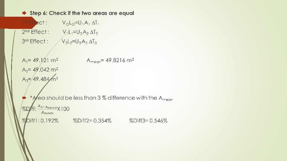
Step 6: Check if the three areas are equal 1 st Effect : VOLO=U 1 A 1 ∆T 1 2 nd Effect : V 1 L 1=U 2 A 2 ∆T 2 3 rd Effect : V 2 L 2=U 3 A 3 ∆T 3 A 1= 53. 564 m 2 A 2= 50. 706 m 2 A 3= 45. 356 m 2 Amean= 49. 875 m 2
* Area must be less than 3 % difference with the Amean
Repeat Step 3: temperature and enthalpy profile To=398. 15 K L 0=2198. 165 k. J/kg T 1=381. 725 K L 1=2243. 8754 k. J/kg T 2=362. 289 K L 2=2294. 2492 k. J/kg T 3=340. 558 K L 3= 2300. 8421 k. J/kg Step 4: Energy Balance in 3 Evaporators 1 st Effect : Vo. Lo=(F V 3 V 2)Cp(T 1 T 2)+V 1 L 1 2 nd Effect : V 1 L 1=(F V 3)Cp(T 2 T 3)+V 2 L 2 3 rd Effect: V 2 L 2=FCp(T 3 Tf)+V 3 L 3 Step 5: Solve for stream rates Vo, V 1, V 2 , V 3 Vo= 3. 3033 x 103 V 1= 3. 05841 x 103 V 2=2. 69978 x 103 V 3=1. 90847 X 103
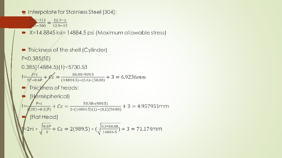
A= ᴨ*D*L Diameter and length has a ratio of 1: 4 L=4 D 49. 83= ᴨ*D*(4 D) D=1. 9793 m L= 4 D= 7. 9173 m Maximum Allowable Working Pressure: 233. 54 k. Pa*(14. 7/101. 325)= 33. 88145 psia 33. 88145+ 25= 58. 88 psia Maximum Allowable Temperature: 125°C+ 30°C= 155°C= 311°F
Equipment Specification Material of Construction Stainless steel (304) will be used as the material of construction because it does not readily corrode, rust or stain with this kind of feed solution as ordinary steel does.
Shell Specifications a. Material: stainless steel: type (304) b. Maximum allowable stress of stainless steel = 14884. 5 psi c. Length: 7. 916 meters d. Diameter: 1. 979 meters e. Thickness: 6. 9236 mm f. Evaporator heads(thickness): hemispherical(4. 958 mm) & flat head(71. 174 mm)
Pipe Inside the Evaporator Specifications (Assume: Based on Heuristics) a. Material: 3 1/3 Schedule 40 stainless steel b. Length: 5 meters c. Inside Pipe Diameter: 3. 5 in d. Outside Pipe Diameter: 3. 334 in e. Number of tubes: 20 tubes (maximum)
Heuristics Maximum allowable PRESSURE AND TEMPERATURE Operating pressure inside is up to 233. 54 KPa. Design pressure for these evaporators are equal to operating pressure plus 25 psig or 10%. Design temperature is equal to Operating temperature plus 30°C or 50°F. Shell and head thickness is obtain with design pressure and design temperature. Computing for diameter and length: having a ratio of 1: 4. Maximum allowable stress is dependent on the material of construction and the design temperature. Internal tubes for the evaporator can be range to 19– 63 mm (0. 75– 24. 8 in. ) in diameter and 3. 66– 9. 14 m (12– 30 ft) long. For corrosion allowance, 3 mm is consider because the feed is not corrosive. Also welded joint efficiency 1. 00 because it is assume that the equipment is a single/ double-welded butt joint that is fully radiographed.
3 D DIAGRAM
Prototype
REFERENCES: http: //nptel. ac. in/courses/103107096/module 4/lecture 2. pdf http: //www. spxflow. com/cn/assets/pdf/Evaporator_Handbook_10003_01_08_2008_US. pdf https: //www. bma worldwide. com/products/sugar and sweeteners/tubular fallingfilm evaporator. html http: //multiple effect evaporation. webs. com/ http: //rajprocessequipment. com/download/EVAPORATOR. doc