Multimedie och kommunikationssystem lektion 6 Kap 6 Fort


 03 5 (Nämnare) 171 7 Nominator (Täljare) . 15 2 Reminder")


, x 2")

 q The redundant bits are chosen in such a")


 Error Control (Felhantering) • •")


 Protocol The simplest protocol for error and flow control")
 error free;")
 corrupted I-frame;")

 corrupted ACK-frame.")


 q Based upon HDLC q Used for point-to-point access q Common")

- Slides: 91
Multimedie- och kommunikationssystem, lektion 6 Kap 6: Fort. digital transmission. Felhantering.
Note: In a single-bit error, only one bit in the data unit has changed.
10. 1 Single-bit error
Note: A burst error means that 2 or more bits in the data unit have changed.
10. 2 Burst error of length 5
Note: Error detection uses the concept of redundancy, which means adding extra bits for detecting errors at the destination.
10. 3 Redundancy
10. 4 Detection methods
Note: In parity check, a parity bit is added to every data unit so that the total number of 1 s is even (or odd for odd-parity).
Example 1 Suppose the sender wants to send the word world. In ASCII (7 -bit code) the five characters are coded as 11101111 1110010 1101100100 Even parity is used. The following shows the actual bits sent: 1110 110111100100 11011000 11001001
Example 3 Now suppose the word world in Example 1 is received by the receiver without being corrupted in transmission. 1110 110111100100 11011000 11001001 The receiver counts the 1 s in each character and comes up with even numbers (6, 6, 4, 4, 4). The data are accepted. Now suppose the word world in Example 1 is corrupted during transmission. 11111110 110111101100 11011000 11001001 The receiver counts the 1 s in each character and comes up with even and odd numbers (7, 6, 5, 4, 4). The receiver knows that the data are corrupted, discards them, and asks for retransmission.
Note: Simple parity check can detect all single-bit errors. It can detect burst errors only if the total number of errors in each data unit is odd.
Note: In two-dimensional parity check, a block of bits is divided into rows and a redundant row of bits is added to the whole block.
10. 6 Two-dimensional parity
Example 4 Suppose the following block is sent: 10101001 00111001 1101 11100111 1010 However, it is hit by a burst noise of length 8, and some bits are corrupted. 101000001001 1101 11100111 1010 When the receiver checks the parity bits, some of the bits do not follow the even-parity rule and the whole block is discarded. 101000001001 1101 11100111 1010
10. 7 CRC generator and checker CRC = Cyclic Redundency Check
”Vanlig” division (Kvot) 03 5 (Nämnare) 171 7 Nominator (Täljare) . 15 2 Reminder (Rest) Haltande liknelse med CRC: Om vi subtraherar täljaren (17) med resten (2) vi ett tal som är jämnt delbart med nämnaren (5). Om mottagaren tar emot något som inte är delbart med 5 har sannolikt att bitfel uppstått.
Modulo 2 Arithmetic q In modulo 2 arithmetic addition and substruction are identical to EXCLUSUVE OR (XOR) operation. q Multiplication and division are the same as in base-2 arithmetic without carries in addition or borrows in substraction. 0 XOR 0 = 0 0 XOR 1 = 1 1 XOR 0 = 1 1 XOR 1 = 0 Examples: 1011 XOR 0101 = 1110 1001 XOR 1101 = 0100
10. 8 Binary division in a CRC generator The number of 0 s is one less than the number of bits in G (divisor)
10. 8 Binary division in a CRC generator The first bit in the numerator is 1. Then the first bit in the quotient is 1. The first bit in the quotient is 1 and one times the divisor results in this Obtained by XOR -ing 1001 and 1101
10. 8 Binary division in a CRC generator Transmitted data: 1 0 0 0 0 1
10. 9 Binary division in CRC checker
Another Example The transmitted data is 11010110111110
10. 11 A polynomial representing a divisor 7 th order polynomial 8 bit divisor
Polynomyal representation q Based upon discrete mathetematics, where bit strings are treated as polynomials. q k bit divisor is represented as (k-1) degree polynomial with coefficients 0 and 1. q Example: 1010110 has 7 bits q It can be represented as a polynomial of 6 th degree 1·x 6 + 0·x 5 + 1·x 4 +0·x 3 + 1·x 2 + 1·x 1 + 0·x 0 = x 6 + x 4 + x 2 + x
Table 10. 1 Standard polynomials Name Polynomial Application CRC-8 x 8 + x 2 + x + 1 ATM header CRC-10 x 10 + x 9 + x 5 + x 4 + x 2 + 1 ATM AAL ITU-16 x 16 + x 12 + x 5 + 1 HDLC ITU-32 x 32 + x 26 + x 23 + x 22 + x 16 + x 12 + x 11 + x 10 + x 8 + x 7 + x 5 + x 4 + x 2 + x + 1 LANs
Example 5 It is obvious that we cannot choose x (binary 10), x 2 (binary 100), etc, because then the reminder is 0. We cannot chose a polynomial that is divisible by x, for example x 2 + x (binary 110). However, we can choose x + 1 (binary 11) because it is not divisible by x, but is divisible by x + 1. We can also choose x 2 + 1 (binary 101) because it is divisible by x + 1 (binary division).
How CRC Operates q The sender wants to send k bits message q The sender and the receiver must agree in advance on n+1 bit string called generator polynomial (divisor), G. m G can be represented as n-degree polynomial q n redundant bits are added to the k bits message. They are called CRC bits. k bits Data bits to be sent n bits CRC bits
How CRC Operates (Cont. ) q The redundant bits are chosen in such a way that the resulting k+n bit string is exactly divisible (with a reminder=0) by G using modulo 2 arithmetic. q The receiver divides the received data together with the CRC bits by G using modulo 2 arithmetic. m If the reminder is 0, then the string is considered to be without errors m If the reminder is not 0, the data unit is with errors and it is rejected
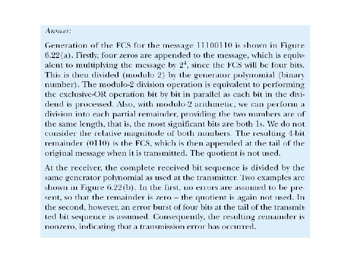
Example 6 The CRC-12 x 12 + x 11 + x 3 + x + 1 which has a degree of 12, will detect all burst errors affecting an odd number of bits, will detect all burst errors with a length less than or equal to 12, and will detect, 99. 97 percent of the time, burst errors with a length of 12 or more.
Example 6. 7: CRC
Note: The sender follows these steps: • The unit is divided into k sections, each of n bits. • All sections are added using one’s complement to get the sum. • The sum is complemented and becomes the checksum. • The checksum is sent with the data.
Column: Carry from column 5 Example 7 6 5 3 2 1 1 0 Carry from column 4 1 Carry from column 3 q n=5 bit checksum. q 20 bit data gives k=20/n=4 sections (rows). q The addition starts in the last column. q The bits are carried in the columns before. q The 6 th and 7 th bit are added q The sum is complemented 4 1 1 Carry from column 2 1 Carry from column 1 1 0 Sum Checksum 0 0 1 1 0 0 0 1 1 1 1 0 0 1 1 0
Example 7 Suppose the following block of 16 bits is to be sent using a checksum of 8 bits. 10101001 00111001 The numbers are added using one’s complement 10101001 Sum 00111001 ------11100010 Checksum 00011101 The pattern sent is 10101001 00111001 00011101
Note: The receiver follows these steps: • The unit is divided into k sections, each of n bits. • All sections are added using one’s complement to get the sum. • The sum is complemented. • If the result is zero, the data are accepted: otherwise, rejected.
Example 8 Now suppose the receiver receives the pattern sent in Example 7 and there is no error. 10101001 00111001 00011101 When the receiver adds the three sections, it will get all 1 s, which, after complementing, is all 0 s and shows that there is no error. 10101001 00111001 00011101 Sum 1111 Complement 0000 means that the pattern is OK.
Example 9 Now suppose there is a burst error of length 5 that affects 4 bits. 101011111001 00011101 When the receiver adds the three sections, it gets 101011111001 00011101 Partial Sum 1 11000101 Carry Sum Complement 1 11000110 00111001 the pattern is corrupted.
11. 1 Flow and Error Control Flow Control (Flödesstyrning) Error Control (Felhantering) • • Båda dessa funktioner hanteras av vissa datalänkprotokoll (lager 2), i LLC-sublagret, t. ex. vid trådlös kommunikation eller vid modem. End-to-end flödesstyrning och felkontroll hanteras av transportprotokollet TCP (lager 4).
Flow control Necessary when data is being sent faster than it can be processed by receiver to avoid that the receiver’s buffer is overwhelmed.
Felhantering med hjälp av felrättande koder FEC = Forward Error Correction. Baseras på felrättande istället för felupptäckande koder. Kräver ingen backkanal. Två typer: 1. Faltningskoder (convolutional codes). Ex: Vid Faltningskod med kodtakt (code rate) 1/3 infogas två redundanta bitar mellan varje bit i nyttomeddelandet. Dessa felrättande bitar beräknas kontinuerligt för varje inkommande bit i nyttomeddelandet. 2. Blockkoder (block codes) Ex: I digital-TV-systemet används en s. k. Read Salomon-kod med beteckningen RS(204, 188, 8). Det innebär att nyttoinformationen delas upp i 188 byte stora block. För varje block beräknas en felrättande kod, som läggs till blocket så att blocket blir 204 byte. Redundanden är alltså 204 – 188 = 16 byte. Koden klarar 8 felaktiga byte.
Felhantering med hjälp av felupptäckande koder Alternativ 1: Bortkastning av felaktiga paket. Alternativ 2: ARQ = Automatic Repeat re. Quest = automatisk omsändning av paket vid bitfel, eller om paketet inte når fram. I fortsättning kommer vi med begreppet ”error control” eller ”felkontroll” att avse ARQ.
Protocols to be presented q Idle RQ = Stop-and-wait ARQ q Sliding Window Flow Control q Go-back-N ARQ q Selective Repeat ARQ Sliding Window Protocols
The Idle RQ (Repeat Request) Protocol The simplest protocol for error and flow control How the protocol operates: m Source may not send a new frame until the receiver acknowledges previous one. m The receiver sends only positive acknowledgements (ACK) to notify the sender that the frame was received. m If the frame 0 was received, the ACK 1 is sent. In that way the sender is notified that the receiver is expecting frame 1. m The ID of the frame is called a sequence number. m 1 bit sequence numbers is sufficient. Sequence: 0 1 0. .
Figure 6. 23 Idle RQ error control scheme: (a) error free;
(b) corrupted I-frame;
Figure 6. 24 Idle RQ link utilization.
(c) corrupted ACK-frame.
11. 1 Normal operation ACK n = Acknowledgement. Expecting frame number n
11. 2 Stop-and-Wait ARQ, lost frame
Lost or Damaged Frame q The sender starts a timer when it sends each frame q If the ACK is not received before the timer expires, the sender resends the same frame again
11. 3 Stop-and-Wait ARQ, lost ACK frame
Lost or damaged ACK q Lost ACK causes duplicate frames q A duplicate frame is recognized by the sequence number and is discarded q The receiver sends the same ACK again
11. 4 Stop-and-Wait ARQ, delayed ACK
Note: Numbered acknowledgments are needed if an acknowledgment is delayed and the next frame is lost.
Piggybacking q Usually the communication is in both ways – this means that the sender is a receiver and the receiver is the sender, too. (both send and receive data) q To save on the processing and bandwidth the short ACKs messages are not sent as separate frames. Instead, they may be included in the frames with data. q This technique is called piggybacking
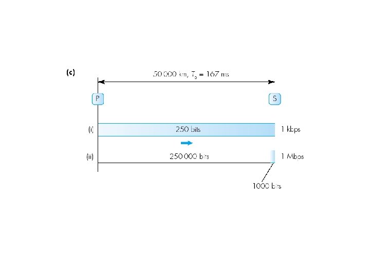
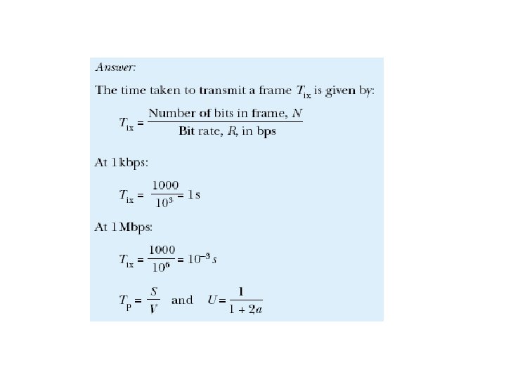
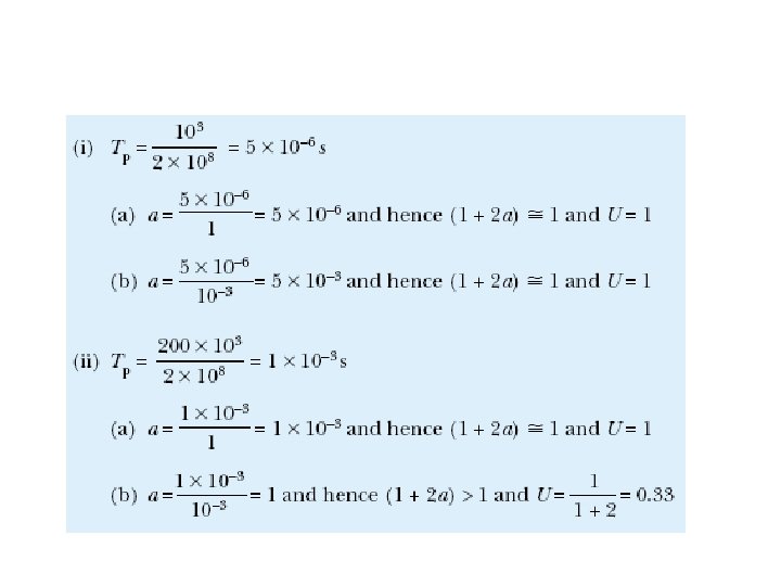
Example 6. 8: Idle RQ
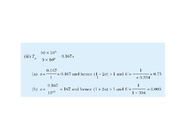
Figure 6. 25 Effect of propagation delay as a function of data transmission rate; parts correspond to Example 6. 8.
Example 6. 9
11. 5 Piggybacking
Efficiency of Stop-and-Wait q Very inefficient, having in mind that most of the time the sender is idle q Example: 40 km copper cable, 10 Mbps rate, 1000 bit frame, m Signal in copper propagates at 2 x 10⁸ m/sec m Transmission time is 1000/10000000 (Takes 0. 1 msec to transmit frame) m Propagation time is 40000/ 2 x 10⁸ (0. 2 msec delay to begin arriving at the receiver) m Total time is 0. 3 msec. to get to the receiver m ACK transmission time is approximately 0 (assuming the ACK is very short (length 0) m 0. 2 msec is the time for the ACK to arrive at the sender q Total time is 0. 5 msec before the sender can transmit again q 0. 5 ms for 0. 1 msec frame or efficiency is 20%
Sliding-Window flow control q Several frames can be sent without acknowledgement being received q N is the window size – the maximum number of frames that can be sent and not being acknowledged. q The receiver must be able to buffer N frames. q Sequence numbers are used to identify each frame. They are carried in the header. q The number of different sequence numbers must be at least N+1. q If the field for sequence numbers allows m bits, the number of different sequence number is 2 m and the sequence numbers range from 0 to 2 m-1. In that case the maximum window size is N = 2 m-1.
11. 6 Sender sliding window The sender window is the set of frames that may be transmitted before an ACK. It slides when the sender has received an ACK and sent next frame.
11. 7 Receiver sliding window The receiver window is the set of frames that may be accepted before the buffer is full. While the buffer is full, the receiver sends no ACK. The window of a stuffed receiver slides when the receiver has ”consumed” a frame and thus sent an ACK.
Stop-and-Wait vs. Sliding Window size N=3. Sender Receiver Fram e 0 ACK 0 Fram e 1 ACK 1 Fram e 0 ACK 0. . . Sequence numbers are 1 bit long (0 or 1) Transmission + propagation Transmiss time for the ion time packet for the packet Transmission + propagation time for the ACK Time Sender Frame consumption delay Receiver Fram e 0 Fram e Fram 1. . 1 e 2 AC. K 2 ACK 3 ACK propagation time Frame consumption delay . . . Sequence numbers from 0 to 2 m-1. m-bit field for the seq. num.
Sender and Receiver Prospective The window size is 7
Sliding Window Flow Control 0 1 2 3 4 5 6 7 0 3 4 5 6 7 0 0 1 2 3 4 5 6 7 0 1 2 3 4 5 6 7 0 0 1 2 3 4 5 6 7 0 1 2 3 4 5 6 7 0 0 1 2 3 4 5 6 7 0 F 1 ACK 1 0 1 2 3 4 5 6 7 0 F 2 ACK 2 F 3 0 1 2 3 4 5 6 7 0 ACK 3 F 4 0 1 2 3 4 5 6 7 0 1 2 3 4 5 6 7 0 ACK 4 F 5 ACK 6 N=6
ARQ with Sliding Window Problems arise when some of the frames are discarded (errors or lost frames). Two strategies are developed to deal with this problem: q Go-back-N strategy m The reciever simply discards all frames after the damaged frame without sending acknowledgement. q Selective repeat strategy m The receiver keeps all the frames after the damaged frame. It sends negative acknowledgement (NACK) for the damaged frame. When the sender finaly notice that something is wrong it retransmits the bad frame. The two strategies are trade-offs between bandwidth and data-link buffer space.
Go-Back-N Strategy q If a frame is lost, the lost frame and all the frames sent after it are sent again. q Sending window of size N, receiving window of size 1. q The sender has to buffer N frames q Bandwidth is wasted.
11. 9 Go-Back-N ARQ, normal operation
11. 10 Go-Back-N ARQ, lost frame
11. 11 Go-Back-N ARQ: sender window size
Selective Repeat Strategy q Only retransmit the frames that are in error q Both sending and receiving window are of size N
11. 13 Selective Repeat ARQ, lost frame
11. 14 Selective Repeat ARQ, sender window size
Bandwidth – Delay Product q The product of the bit rate (bandwidth expressed as bits per seconds) and the propagation time gives the number of bits that can be on the channel and thus can give orientation about the window size q When propagation time is high (for example in satellite channels), the window size need to be larger
Example 1 In a Stop-and-Wait ARQ system, the bandwidth of the line is 1 Mbps, and 1 bit takes 20 ms to make a round trip. What is the bandwidth-delay product? If the system data frames are 1000 bits in length, what is the utilization percentage of the link? Solution The bandwidth-delay product is 1 106 20 10 -3 = 20, 000 bits The system can send 20, 000 bits during the time it takes for the data to go from the sender to the receiver and then back again. However, the system sends only 1000 bits. We can say that the link utilization is only 1000/20, 000, or 5%. For this reason, for a link with high bandwidth or long delay, use of Stop-and-Wait ARQ wastes the capacity of the link.
Example 2 What is the utilization percentage of the link in Example 1 if the link uses Go. Back-N ARQ with a 15 -frame sequence? Solution The bandwidth-delay product is still 20, 000. The system can send up to 15 frames or 15, 000 bits during a round trip. This means the utilization is 15, 000/20, 000, or 75 percent. Of course, if there are damaged frames, the utilization percentage is much less because frames have to be resent.
High-level Data Link Control Protocol q HDLC is one of the first protocols that implements mechanisms of ARQ q Supports half-duplex and full-duplex mode on point-to-point links q Uses three types of frames: information (I-frames), supervisory (Sframes) and unnumbered (U-frames) q Only I frames carry information, S frames carry transport control information and U frames are used for managing the link
HDLC Frame Structure Flag Address Control q Flag: 01111110, at start and end q Physical Address: secondary station (for multidrop configurations) q Information: the data to be transmitted q Frame check sequence (FCS): 16 - or 32 -bit CRC Information FCS Flag q Control: purpose or function of frame m Information frames: contain user data m Supervisory frames: flow/error control (ACK/ARQ) m Unnumbered frames: variety of control functions (see p. 220)
11. 18 HDLC frame types
The Need for Bit Stuffing q The flags show the receiver the start and the end of frame q There is a problem if the flag appears in the middle of the frame as a part of data q The receiver will ”think” it is the end of frame q A technique called “bit stuffing” is used to resolve this problem
Bit Stuffing q The sender stuffs redundant 0 s m Every time it encounters five 1 s in a row, it inserts a redundant 0 m The redundant 0 tells the receiver that the sequence is not a flag m The receiver removes all redundant 0 s to restore the original frame m Example: Bit stuff the following data: 00011111011110001111101111000111110011 Redundant 0 s
11. 24 Bit stuffing and removal
11. 25 Bit stuffing in HDLC
PPP (Point-to-Point Protocol) q Based upon HDLC q Used for point-to-point access q Common protocol used for connecting home users to the Internet (via dial-up, DSL or cable modem or leased line) q Defines the negotiation for establishment of the link q Defines the protocol carried on the network layer q Includes authentication and a field about the type of network protocol carried within the frame
PPP Frame Format Number of bytes in a field 1 1 or 2 Flag Address Control Protocol 01111110 1111 00000011 variable Payload 2 or 4 CRC 1 Flag 01111110 § Physical Address field with all 1 s indicate broadcasting, i. e. that all stations accept the frame § Since the Address and Control fields are constant, the two parties can negotiate to omit them, thus saving 2 bytes § Protocol field defines what is carried in the payload field (user data or other information) § CRC bits are error control bits