Multimedie och kommunikationssystem lektion 5 Kap 6 Digital

 twowire and multiwire open lines; (b)")
 shielded twisted pair (STP); (d) coaxial")
 Optical fiber transmission modes.")


")


 Manchester; (b) differential Manchester.")


 FSK = Frequency Shift")


 Exempel på FDM-teknik: ADSL-modem, kabel-TV-modem, trådlös")

, each transmitting at 1 Mbps, use a satellite")

 uses two bands. The first band,")
")


")


 Voice Channels E-1 2.")
- Slides: 56
Multimedie- och kommunikationssystem, lektion 5 Kap 6: Digital transmission. Fysiskt medium. Modulation. Nyquists och Shannons kapacitetsgränser.
Figure 6. 3 Copper wire transmission media: (a) twowire and multiwire open lines; (b) unshielded twisted pair (UTP);
Figure 6. 3 Copper wire transmission media: (c) shielded twisted pair (STP); (d) coaxial cable.
Figure 6. 4 (b) Optical fiber transmission modes.
Figure 6. 2 Effect of attenuation, distortion, and noise on transmitted signal.
Figure 6. 7 Sources of signal impairment.
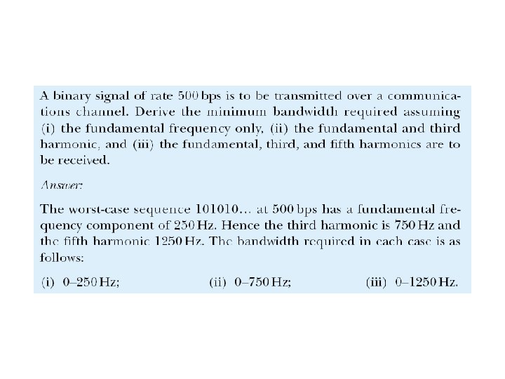
Example 6. 3
Asynchronous transmission
Exempel på asynkron serie-kommunikation: RS 232 C (”com-porten”)
NRZ = Non-return to zero.
In NRZ-L the level of the signal is dependent upon the state of the bit. In NRZ-I the signal is inverted if a 1 is encountered.
Bit synchronization RZ encoding
Figure 4. 10 Manchester encoding
Figure 4. 11 Differential Manchester encoding
Figure 6. 15 Synchronous transmission clock encoding methods: (a) Manchester; (b) differential Manchester.
Figure 4. 12 Bipolar AMI encoding
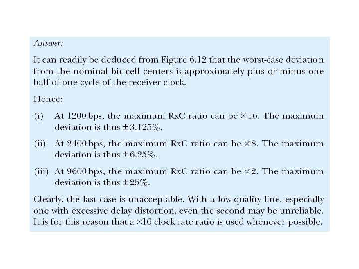
Example 6. 6: Clock rate deviation
Figure 5. 26 Analogue amplitude modulation
Figure 5. 29 Analogue frequency modulation
Digitala modulationsmetoder Binär signal ASK = Amplitude Shift Keying (AM) FSK = Frequency Shift Keying (FM) PSK = Phase Shift Keying (PSK)
Exempel 1: Till höger visas fyra symboler som används av ett s. k. 4 PSKmodem (PSK=Phase Shift Keying). De fyra symbolerna representerar bitföljderna 00, 01, 11 resp 10. a) Nedan visas utsignalen från det sändande modemet. Vilket meddelande, dvs vilken bitsekvens, överförs? 1 0 -1 1 Svar: 1/1 ms = 1000 symber per sekund = 1 kbaud. c) Vad är bithastigheten i bit per sekund (bps)? Svar: 2000 bps. 0 0. 5 1 time [milliseconds] 01 0 -1 Svar: 11 00 10 10. b) Tidsaxeln är graderad i tusendels sekunder. Vad är symbolhastigheten i baud eller symboler/sekund? 00 1 0 0. 5 1 time [milliseconds] 11 0 -1 1 0 0. 5 1 time [milliseconds] 10 0 -1 0 0. 5 1 time [milliseconds]
Exempel 2: Nedan visas åtta symboler som används av ett s. k. 8 QAM-modem (QAM=Quadrature Amplitude Modulation). Symbolerna i övre raden representerar bitföljderna 000, 001, 011 resp 010 (från vänster till höger). Undre raden representerar 100, 101, 111 resp 110.
Forts exempel 2:
Digital modulation q För att överföra N bit/symbol krävs M=2 N q Vid M symboler överförs N=log 2 M bit/symbol. q Baudrate fs= antal symboler per sekund. Enhet: baud eller symboler/sekund. q Symbollängd Ts= 1/fs. fs= 1/Ts q Bitrate R = datahastighet. Enhet: bps eller bit/s. q R= fslog 2 M
Table 5. 1 Bit and baud rate comparison Modulation Units Bits/Symbol Baud rate Bit Rate Bit 1 N N 4 -PSK, 4 -QAM Dibit 2 N 2 N 8 -PSK, 8 -QAM Tribit 3 N 3 N 16 -QAM Quadbit 4 N 4 N 32 -QAM Pentabit 5 N 5 N 64 -QAM Hexabit 6 N 6 N 128 -QAM Septabit 7 N 7 N 256 -QAM Octabit 8 N 8 N ASK, FSK, 2 -PSK
Example 12 Compute the baud rate for a 72, 000 -bps 64 -QAM signal. Solution A 64 -QAM signal has 6 bits per signal unit since log 2 64 = 6. Thus, 72000 / 6 = 12, 000 baud
Figure 5. 9 BPSK constellation
Figure 5. 11 The 4 -PSK characteristics
Figure 5. 16 16 -QAM constellations
Figure 5. 13 Relationship between baud rate and bandwidth in ASK, PSK, QAM (not FSK) without pulse shaping Vid många modulationsformer t. ex. s. k. ASK, PSK, och QAM är signalens bandbredd = symbolhastigheten. Vid FSK är bandbredden vanligen större. Bandbredden kan minskas genom s. k. pulsformning.
Maximal kanalkapacitet enligt Nyquist
Example 6. 4: Nyquist maximum data rate
Shannons regel Kanalkapaciteten C är max antal bit per sekund vid bästa möjliga modulationsteknik och felrättande kodning: C = B log 2 (1+S/N), där B är ledningens bandbredd i Hertz (oftast ungefär lika med övre gränsfrekvensen), S är nyttosignalens medeleffekt i Watt och N (noice) är bruseffekten i Watt.
Example 6. 5: Shannon information capacity
Figure 6. 4 FDM (Frekvensdelningsmultiplex, frequency division multiplex) Exempel på FDM-teknik: ADSL-modem, kabel-TV-modem, trådlös kommunikation.
Figure 6. 5 FDM demultiplexing example
Example 3 Four data channels (digital), each transmitting at 1 Mbps, use a satellite channel of 1 MHz. Design an appropriate configuration using FDM Solution The satellite channel is analog. We divide it into four channels, each channel having a 250 -KHz bandwidth. Each digital channel of 1 Mbps is modulated such that each 4 bits are modulated to 1 Hz. One solution is 16 QAM modulation. Figure 6. 8 shows one possible configuration.
Figure 6. 8 Example 3
Example 4 The Advanced Mobile Phone System (AMPS) uses two bands. The first band, 824 to 849 MHz, is used for sending; and 869 to 894 MHz is used for receiving. Each user has a bandwidth of 30 KHz in each direction. The 3 KHz voice is modulated using FM, creating 30 KHz of modulated signal. How many people can use their cellular phones simultaneously? Solution Each band is 25 MHz. If we divide 25 MHz into 30 KHz, we get 833. In reality, the band is divided into 832 channels.
6. 2 WDM Wave Division Multiplexing (Fiber optics)
Figure 6. 10 WDM = Wave division multiplexing En laser per kanal Fiberkabel
Figure 6. 11 Prisms in WDM multiplexing and demultiplexing
Figure 6. 12 TDM, Tidsmultiplex (Time Division multiplex)
Note: TDM is a digital multiplexing technique to combine data.
Figure 6. 13 TDM frames
Note: In a TDM, the data rate of the link is n times faster, and the unit duration is n times shorter.
Figure 6. 14 Interleaving
Example 6 Four channels are multiplexed using TDM. If each channel sends 100 bytes/s and we multiplex 1 byte per channel, show the frame traveling on the link, the size of the frame, the duration of a frame, the frame rate, and the bit rate for the link. Solution The multiplexer is shown in Figure 6. 15.
Figure 6. 15 Example 6
Example 7 A multiplexer combines four 100 -Kbps channels using a time slot of 2 bits. Show the output with four arbitrary inputs. What is the frame rate? What is the frame duration? What is the bit rate? What is the bit duration? Solution Figure 6. 16 shows the output for four arbitrary inputs.
Figure 6. 16 Example 7
Figure 6. 18 DS hierarchy
Figure 6. 19 T-1 line for multiplexing telephone lines
Table 6. 2 E line rates E Line Rate (Mbps) Voice Channels E-1 2. 048 30 E-2 8. 448 120 E-3 34. 368 480 E-4 139. 264 1920