
MultiLMK 0482 xLMK 04832 SYNC Goals Understand some

- Slides: 33
Multi-LMK 0482 x/LMK 04832 SYNC Goals: • Understand some theory about synchronization • Quickly discuss the main points of JESD 204 B Subclass 1 and clocking • See different techniques to SYNC multiple LMK devices 1
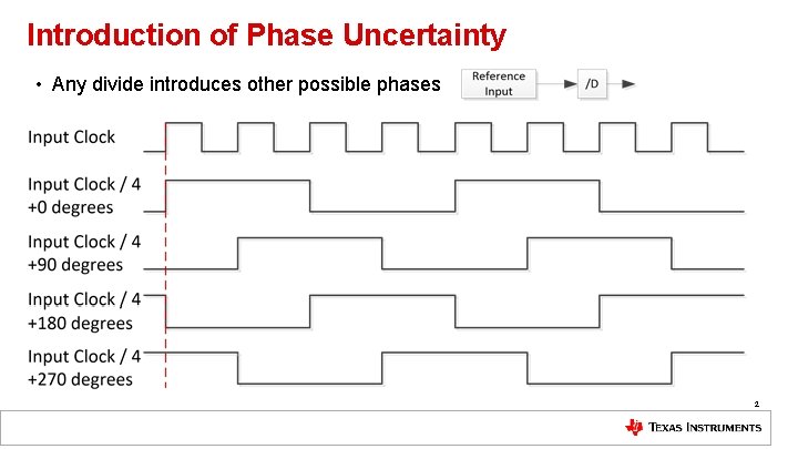
Introduction of Phase Uncertainty • Any divide introduces other possible phases 2
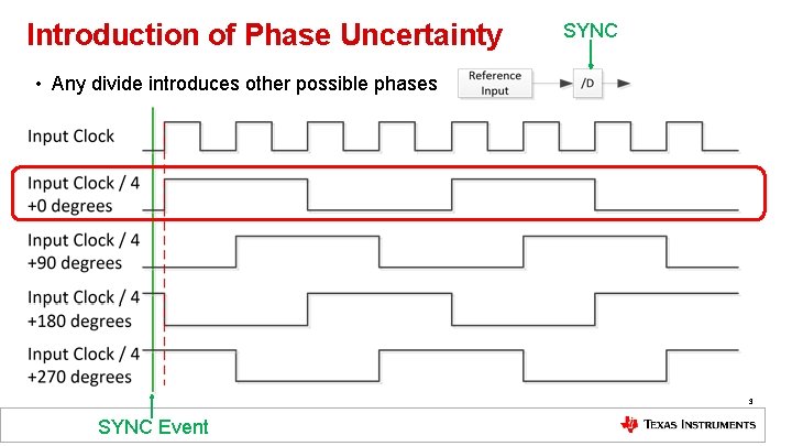
Introduction of Phase Uncertainty SYNC • Any divide introduces other possible phases 3 SYNC Event
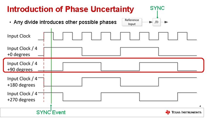
Introduction of Phase Uncertainty SYNC • Any divide introduces other possible phases 4 SYNC Event
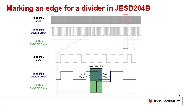
Marking an edge for a divider in JESD 204 B 5
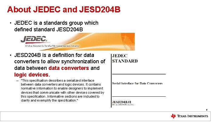
About JEDEC and JESD 204 B • JEDEC is a standards group which defined standard JESD 204 B • JESD 204 B is a definition for data converters to allow synchronization of data between data converters and logic devices. – “This specification describes a serialized interface between data converters and logic devices. It contains normative information to enable designers to implement devices that communicate with other devices covered by this specification. Informative sections are included to clarify and exemplify the specification. ” 6
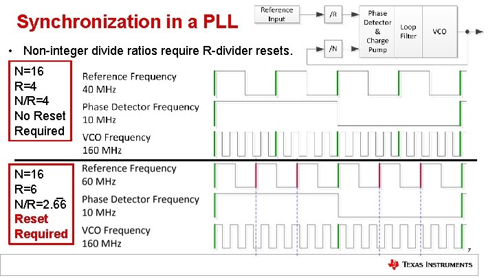
Synchronization in a PLL • Non-integer divide ratios require R-divider resets. N=16 R=4 N/R=4 No Reset Required N=16 R=6 N/R=2. 6 6 Reset Required 7
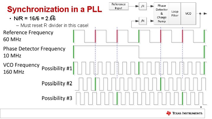
Synchronization in a PLL • N/R = 16/6 = 2. 6 6 – Must reset R divider in this case! 8
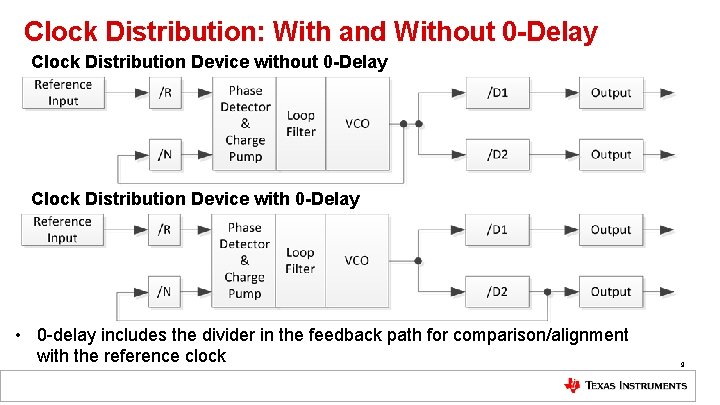
Clock Distribution: With and Without 0 -Delay Clock Distribution Device with 0 -Delay • 0 -delay includes the divider in the feedback path for comparison/alignment with the reference clock 9
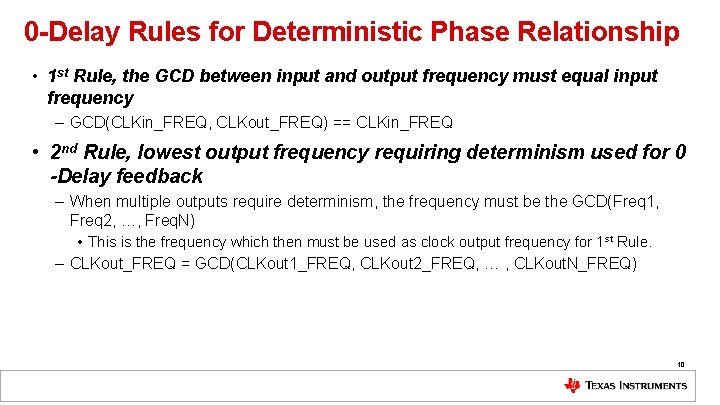
0 -Delay Rules for Deterministic Phase Relationship • 1 st Rule, the GCD between input and output frequency must equal input frequency – GCD(CLKin_FREQ, CLKout_FREQ) == CLKin_FREQ • 2 nd Rule, lowest output frequency requiring determinism used for 0 -Delay feedback – When multiple outputs require determinism, the frequency must be the GCD(Freq 1, Freq 2, …, Freq. N) • This is the frequency which then must be used as clock output frequency for 1 st Rule. – CLKout_FREQ = GCD(CLKout 1_FREQ, CLKout 2_FREQ, … , CLKout. N_FREQ) 10
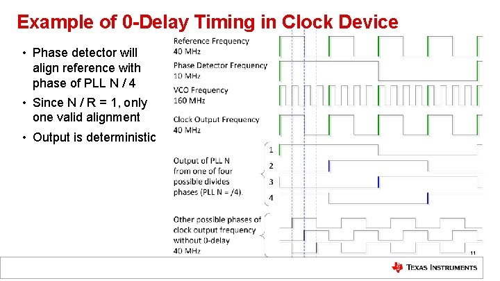
Example of 0 -Delay Timing in Clock Device • Phase detector will align reference with phase of PLL N / 4 • Since N / R = 1, only one valid alignment • Output is deterministic 11
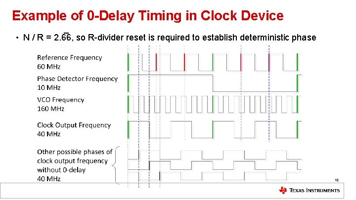
Example of 0 -Delay Timing in Clock Device • N / R = 2. 6 6, so R-divider reset is required to establish deterministic phase 12
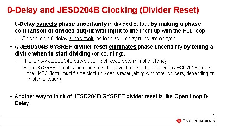
0 -Delay and JESD 204 B Clocking (Divider Reset) • 0 -Delay cancels phase uncertainty in divided output by making a phase comparison of divided output with input to line them up with the PLL loop. – Closed loop: 0 -delay aligns itself, as long as 0 -delay rules are obeyed • A JESD 204 B SYSREF divider reset eliminates phase uncertainty by telling a divide when to start dividing (or counting). – This is how JESD 204 B sub-class 1 achieves deterministic latency. • The SYSREF signal is the divider reset. It synchronizes the divider. In JESD 204 B words, the LMFC (local multi-frame clock) divider is reset (along with other dividers, depending on implementation) • Another way to think of JESD 204 B SYSREF divider reset is like Open Loop 0 Delay. 13
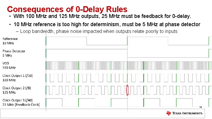
Consequences of 0 -Delay Rules • With 100 MHz and 125 MHz outputs, 25 MHz must be feedback for 0 -delay. • 10 MHz reference is too high for determinism, must be 5 MHz at phase detector – Loop bandwidth, phase noise impacted when outputs relate poorly to inputs 14
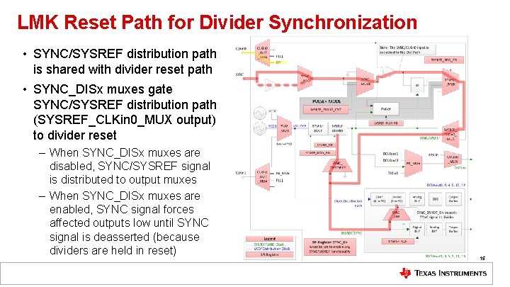
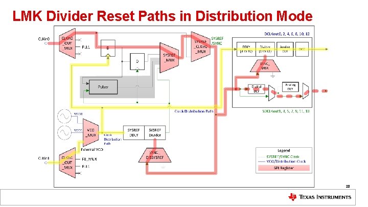
LMK Reset Path for Divider Synchronization • SYNC/SYSREF distribution path is shared with divider reset path • SYNC_DISx muxes gate SYNC/SYSREF distribution path (SYSREF_CLKin 0_MUX output) to divider reset – When SYNC_DISx muxes are disabled, SYNC/SYSREF signal is distributed to output muxes – When SYNC_DISx muxes are enabled, SYNC signal forces affected outputs low until SYNC signal is deasserted (because dividers are held in reset) 15
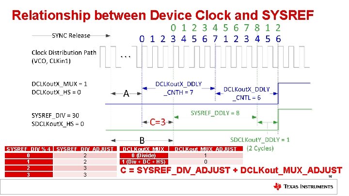
Relationship between Device Clock and SYSREF_DIV % 4 0 1 2 3 SYSREF_DIV_ADJUST 2 2 3 3 DCLKout. X_MUX 0 (Divide) 1 (Div + DC + HS) DCLKout_MUX_ADJUST 1 0 C = SYSREF_DIV_ADJUST + DCLKout_MUX_ADJUST 16
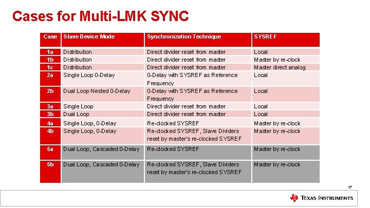
Cases for Multi-LMK SYNC Case Slave Device Mode Synchronization Technique SYSREF 3 a 3 b Single Loop Dual Loop Direct divider reset from master 0 -Delay with SYSREF as Reference Frequency Direct divider reset from master Local Master by re-clock Master direct analog Local 2 b Distribution Single Loop 0 -Delay Dual Loop Nested 0 -Delay 4 a 4 b Single Loop, 0 -Delay Re-clocked SYSREF, Slave Dividers reset by master’s re-clocked SYSREF Master by re-clock 5 a Dual Loop, Cascaded 0 -Delay Re-clocked SYSREF Master by re-clock 5 b Dual Loop, Cascaded 0 -Delay Re-clocked SYSREF, Slave Dividers reset by master’s re-clocked SYSREF Master by re-clock 1 a 1 b 1 c 2 a Local 17
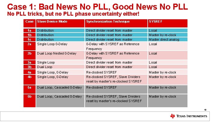
Case 1: Bad News No PLL, Good News No PLL tricks, but no PLL phase uncertainty either! Case Slave Device Mode Synchronization Technique SYSREF 3 a 3 b Single Loop Dual Loop Direct divider reset from master 0 -Delay with SYSREF as Reference Frequency Direct divider reset from master Local Master by re-clock Master direct analog Local 2 b Distribution Single Loop 0 -Delay Dual Loop Nested 0 -Delay 4 a 4 b Single Loop, 0 -Delay Re-clocked SYSREF, Slave Dividers reset by master’s re-clocked SYSREF Master by re-clock 5 a Dual Loop, Cascaded 0 -Delay Re-clocked SYSREF Master by re-clock 5 b Dual Loop, Cascaded 0 -Delay Re-clocked SYSREF, Slave Dividers reset by master’s re-clocked SYSREF Master by re-clock 1 a 1 b 1 c 2 a Local 18
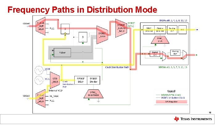
Frequency Paths in Distribution Mode 19
LMK Divider Reset Paths in Distribution Mode 20
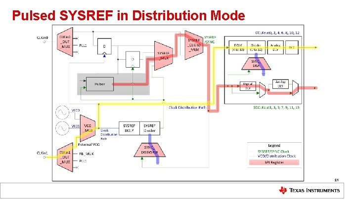
Pulsed SYSREF in Distribution Mode 21
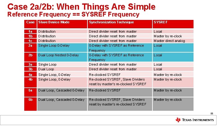
Case 2 a/2 b: When Things Are Simple Reference Frequency == SYSREF Frequency Case Slave Device Mode Synchronization Technique SYSREF 3 a 3 b Single Loop Dual Loop Direct divider reset from master 0 -Delay with SYSREF as Reference Frequency Direct divider reset from master Local Master by re-clock Master direct analog Local 2 b Distribution Single Loop 0 -Delay Dual Loop Nested 0 -Delay 4 a 4 b Single Loop, 0 -Delay Re-clocked SYSREF, Slave Dividers reset by master’s re-clocked SYSREF Master by re-clock 5 a Dual Loop, Cascaded 0 -Delay Re-clocked SYSREF Master by re-clock 5 b Dual Loop, Cascaded 0 -Delay Re-clocked SYSREF, Slave Dividers reset by master’s re-clocked SYSREF Master by re-clock 1 a 1 b 1 c 2 a Local 22
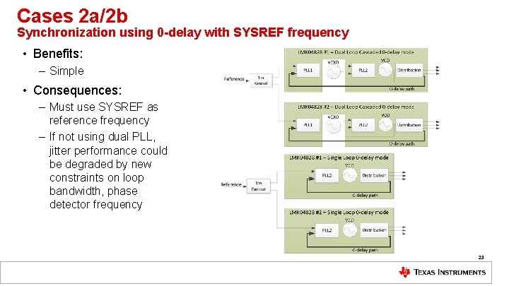
Cases 2 a/2 b Synchronization using 0 -delay with SYSREF frequency • Benefits: – Simple • Consequences: – Must use SYSREF as reference frequency – If not using dual PLL, jitter performance could be degraded by new constraints on loop bandwidth, phase detector frequency 23
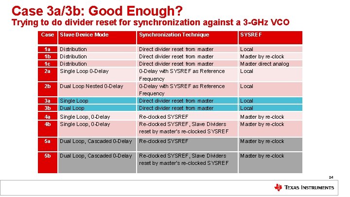
Case 3 a/3 b: Good Enough? Trying to do divider reset for synchronization against a 3 -GHz VCO Case Slave Device Mode Synchronization Technique SYSREF 3 a 3 b Single Loop Dual Loop Direct divider reset from master 0 -Delay with SYSREF as Reference Frequency Direct divider reset from master Local Master by re-clock Master direct analog Local 2 b Distribution Single Loop 0 -Delay Dual Loop Nested 0 -Delay 4 a 4 b Single Loop, 0 -Delay Re-clocked SYSREF, Slave Dividers reset by master’s re-clocked SYSREF Master by re-clock 5 a Dual Loop, Cascaded 0 -Delay Re-clocked SYSREF Master by re-clock 5 b Dual Loop, Cascaded 0 -Delay Re-clocked SYSREF, Slave Dividers reset by master’s re-clocked SYSREF Master by re-clock 1 a 1 b 1 c 2 a Local 24
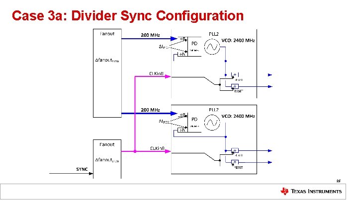
Case 3 a: Divider Sync Configuration 25
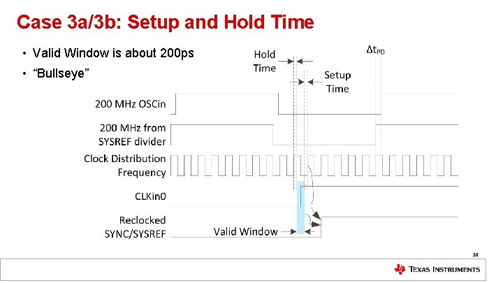
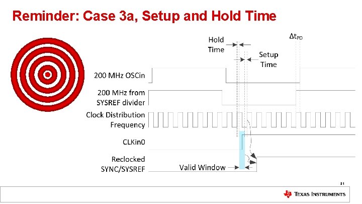
Case 3 a/3 b: Setup and Hold Time • Valid Window is about 200 ps • “Bullseye” 26
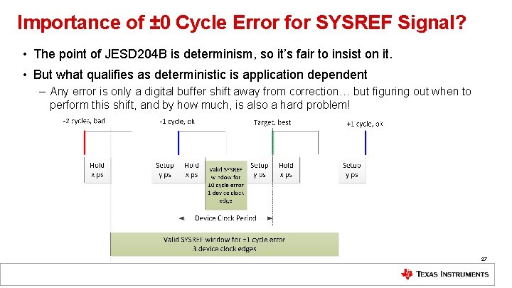
Importance of ± 0 Cycle Error for SYSREF Signal? • The point of JESD 204 B is determinism, so it’s fair to insist on it. • But what qualifies as deterministic is application dependent – Any error is only a digital buffer shift away from correction… but figuring out when to perform this shift, and by how much, is also a hard problem! 27
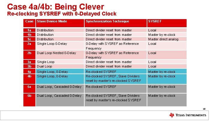
Case 4 a/4 b: Being Clever Re-clocking SYSREF with 0 -Delayed Clock Case Slave Device Mode Synchronization Technique SYSREF 3 a 3 b Single Loop Dual Loop Direct divider reset from master 0 -Delay with SYSREF as Reference Frequency Direct divider reset from master Local Master by re-clock Master direct analog Local 2 b Distribution Single Loop 0 -Delay Dual Loop Nested 0 -Delay 4 a 4 b Single Loop, 0 -Delay Re-clocked SYSREF, Slave Dividers reset by master’s re-clocked SYSREF Master by re-clock 5 a Dual Loop, Cascaded 0 -Delay Re-clocked SYSREF Master by re-clock 5 b Dual Loop, Cascaded 0 -Delay Re-clocked SYSREF, Slave Dividers reset by master’s re-clocked SYSREF Master by re-clock 1 a 1 b 1 c 2 a Local 28
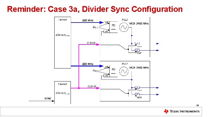
Reminder: Case 3 a, Divider Sync Configuration 29
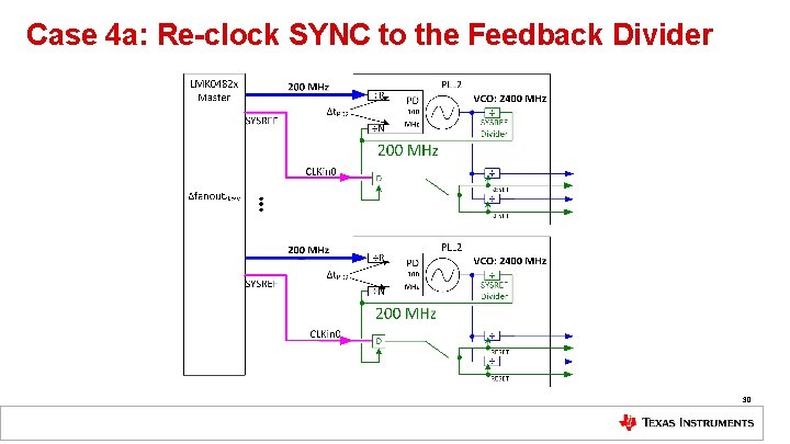
Case 4 a: Re-clock SYNC to the Feedback Divider 30
Reminder: Case 3 a, Setup and Hold Time 31
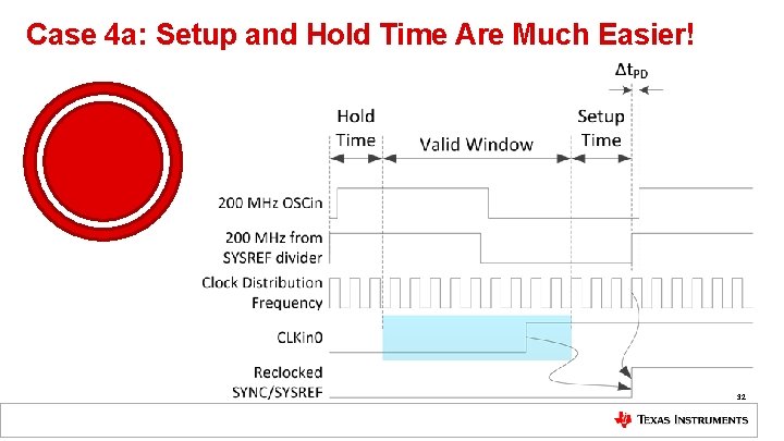
Case 4 a: Setup and Hold Time Are Much Easier! 32
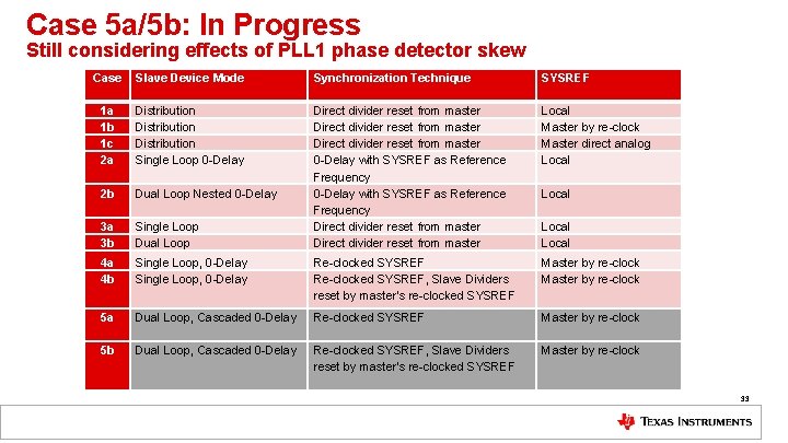
Case 5 a/5 b: In Progress Still considering effects of PLL 1 phase detector skew Case Slave Device Mode Synchronization Technique SYSREF 3 a 3 b Single Loop Dual Loop Direct divider reset from master 0 -Delay with SYSREF as Reference Frequency Direct divider reset from master Local Master by re-clock Master direct analog Local 2 b Distribution Single Loop 0 -Delay Dual Loop Nested 0 -Delay 4 a 4 b Single Loop, 0 -Delay Re-clocked SYSREF, Slave Dividers reset by master’s re-clocked SYSREF Master by re-clock 5 a Dual Loop, Cascaded 0 -Delay Re-clocked SYSREF Master by re-clock 5 b Dual Loop, Cascaded 0 -Delay Re-clocked SYSREF, Slave Dividers reset by master’s re-clocked SYSREF Master by re-clock 1 a 1 b 1 c 2 a Local 33