
Multicycle Datapath Control Andreas Klappenecker CPSC 321 Computer


- Slides: 20
Multicycle Datapath & Control Andreas Klappenecker CPSC 321 Computer Architecture
Administrative Issues n Office hours have been moved: n n Today: canceled Thursday 2: 00 pm-3: 00 pm Seek help if you did not do well on the test Lab 3 due next week
Multi-Cycle Processor
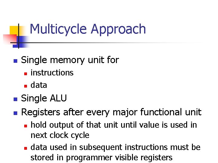
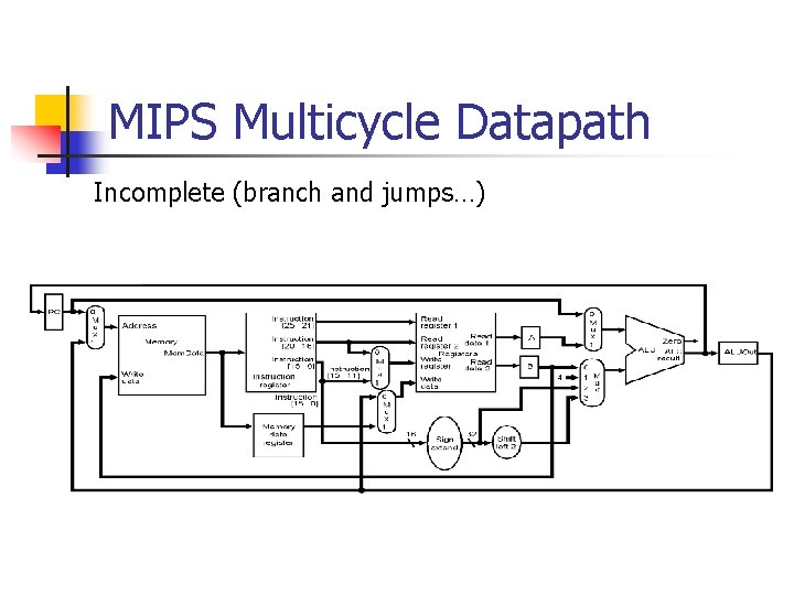
Multicycle Approach n Single memory unit for n n instructions data Single ALU Registers after every major functional unit n n hold output of that unit until value is used in next clock cycle data used in subsequent instructions must be stored in programmer visible registers
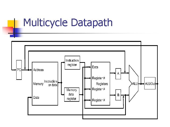
Multicycle Datapath
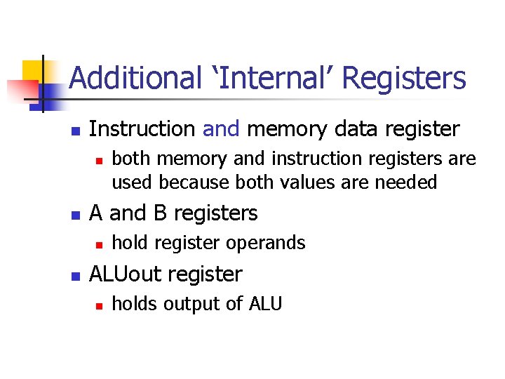
Additional ‘Internal’ Registers n Instruction and memory data register n n A and B registers n n both memory and instruction registers are used because both values are needed hold register operands ALUout register n holds output of ALU
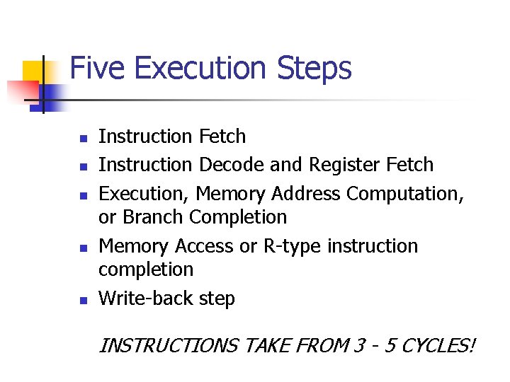
Five Execution Steps n n n Instruction Fetch Instruction Decode and Register Fetch Execution, Memory Address Computation, or Branch Completion Memory Access or R-type instruction completion Write-back step INSTRUCTIONS TAKE FROM 3 - 5 CYCLES!
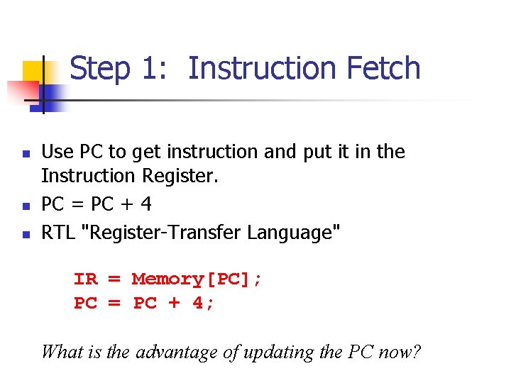
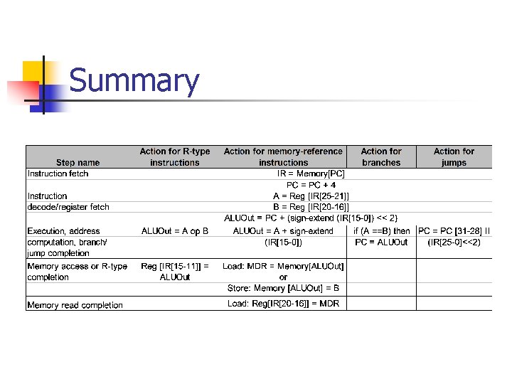
Step 1: Instruction Fetch n n n Use PC to get instruction and put it in the Instruction Register. PC = PC + 4 RTL "Register-Transfer Language" IR = Memory[PC]; PC = PC + 4; What is the advantage of updating the PC now?
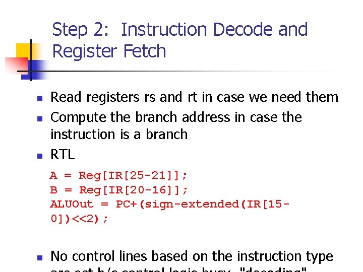
Step 2: Instruction Decode and Register Fetch n n n Read registers rs and rt in case we need them Compute the branch address in case the instruction is a branch RTL A = Reg[IR[25 -21]]; B = Reg[IR[20 -16]]; ALUOut = PC+(sign-extended(IR[150])<<2); n No control lines based on the instruction type
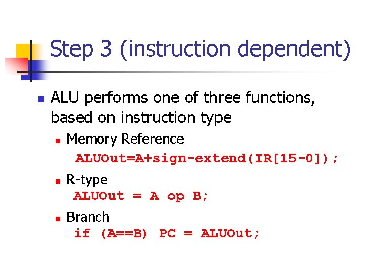
Step 3 (instruction dependent) n ALU performs one of three functions, based on instruction type n n n Memory Reference ALUOut=A+sign-extend(IR[15 -0]); R-type ALUOut = A op B; Branch if (A==B) PC = ALUOut;
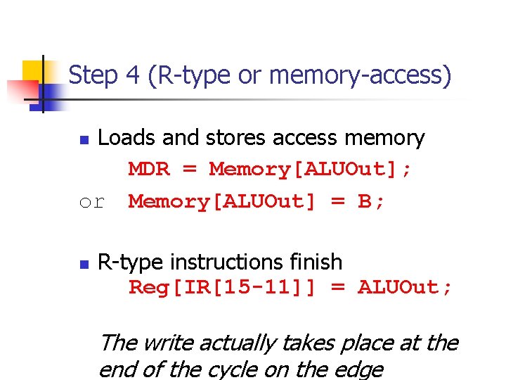
Step 4 (R-type or memory-access) Loads and stores access memory MDR = Memory[ALUOut]; or Memory[ALUOut] = B; n n R-type instructions finish Reg[IR[15 -11]] = ALUOut; The write actually takes place at the end of the cycle on the edge
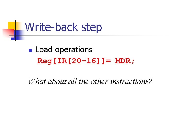
Write-back step n Load operations Reg[IR[20 -16]]= MDR; What about all the other instructions?
Summary
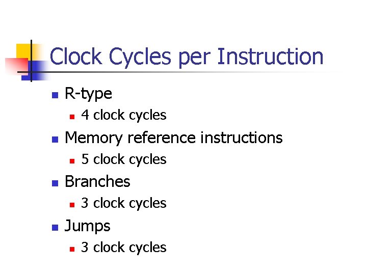
Clock Cycles per Instruction n R-type n n Memory reference instructions n n 5 clock cycles Branches n n 4 clock cycles 3 clock cycles Jumps n 3 clock cycles
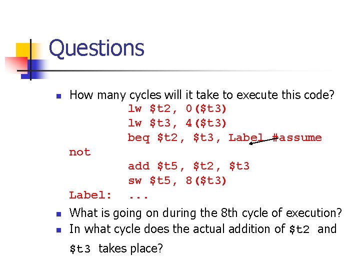
Questions n n n How many cycles will it take to execute this code? lw $t 2, 0($t 3) lw $t 3, 4($t 3) beq $t 2, $t 3, Label #assume not add $t 5, $t 2, $t 3 sw $t 5, 8($t 3) Label: . . . What is going on during the 8 th cycle of execution? In what cycle does the actual addition of $t 2 and $t 3 takes place?
MIPS Multicycle Datapath Incomplete (branch and jumps…)
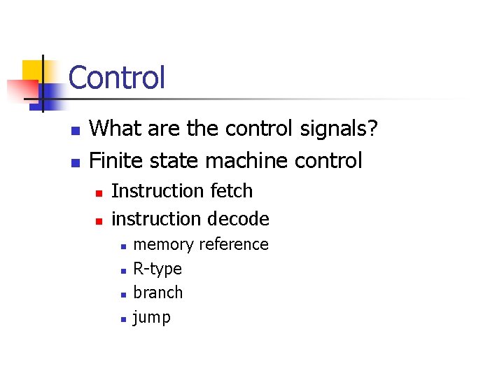
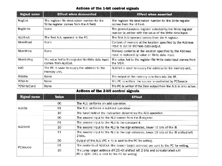
Control n n What are the control signals? Finite state machine control n n Instruction fetch instruction decode n n memory reference R-type branch jump
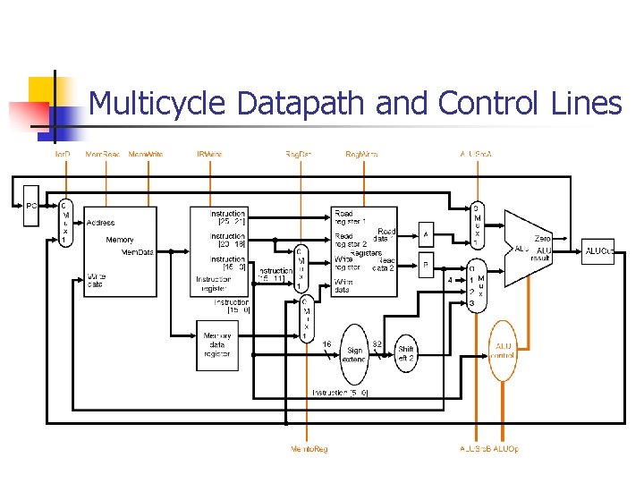
Multicycle Datapath and Control Lines
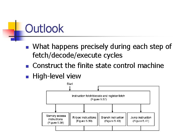
Outlook n n n What happens precisely during each step of fetch/decode/execute cycles Construct the finite state control machine High-level view