
MTA line status C Moore and C Johnstone
- Slides: 13
MTA line status C. Moore and C. Johnstone 11/3/2010
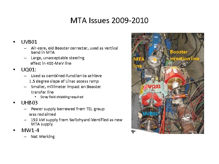
MTA Issues 2009 -2010 • UVB 01 – Air-core, old Booster corrector, used as vertical bend in MTA – Large, unacceptable steering effect in 400 -Me. V line • UQ 01: – Used as combined-function to achieve 1. 5 degree slope of Linac access ramp – Smaller, millimeter impact on Booster transfer line • • MTA line UQ 01 Stray field shielding required UHB 03 – Power supply borrowed from TEL group was reclaimed – 150 k. W supply from Switchyard identified as new MTA supply • Booster injection line MW 1 -4 – Not Working UVB 01
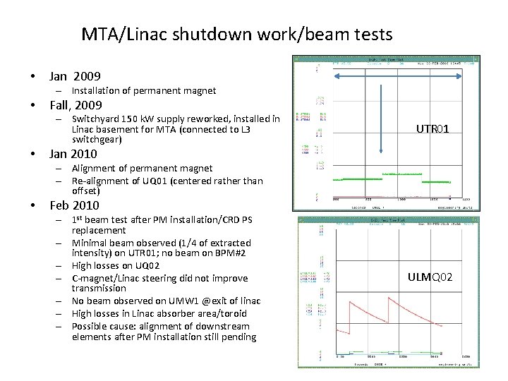
MTA/Linac shutdown work/beam tests • Jan 2009 – Installation of permanent magnet • Fall, 2009 – Switchyard 150 k. W supply reworked, installed in Linac basement for MTA (connected to L 3 switchgear) • UTR 01 Jan 2010 – Alignment of permanent magnet – Re-alignment of UQ 01 (centered rather than offset) • Feb 2010 – 1 st beam test after PM installation/CRD PS replacement – Minimal beam observed (1/4 of extracted intensity) on UTR 01; no beam on BPM#2 – High losses on UQ 02 – C-magnet/Linac steering did not improve transmission – No beam observed on UMW 1 @exit of linac – High losses in Linac absorber area/toroid – Possible cause: alignment of downstream elements after PM installation still pending ULMQ 02
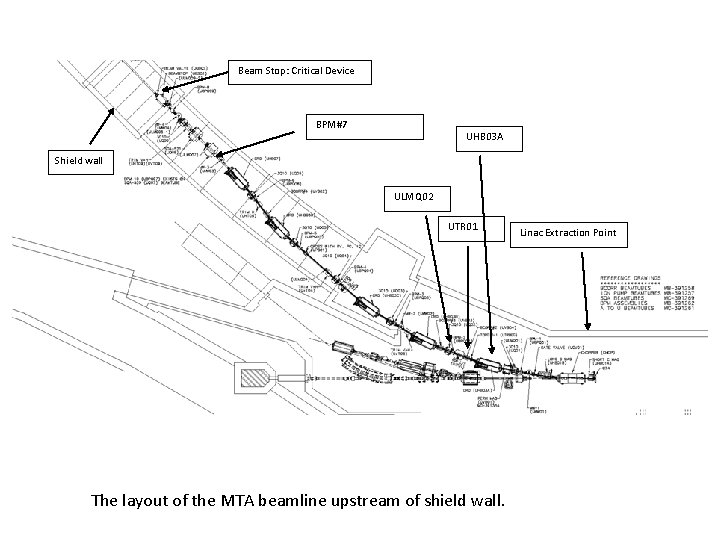
Beam Stop: Critical Device BPM#7 UHB 03 A Shield wall ULMQ 02 UTR 01 The layout of the MTA beamline upstream of shield wall. Linac Extraction Point
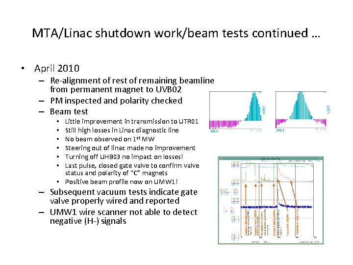
MTA/Linac shutdown work/beam tests continued … • April 2010 – Re-alignment of rest of remaining beamline from permanent magnet to UVB 02 – PM inspected and polarity checked – Beam test Little improvement in transmission to UTR 01 Still high losses in Linac diagnostic line No beam observed on 1 st MW Steering out of linac made no improvement Turning off UHB 03 no impact on losses! Last pulse, closed gate valve to confirm valve status and polarity of “C” magnets • Positive beam profile now on UMW 1! • • • – Subsequent vacuum tests indicate gate valve properly wired and reported – UMW 1 wire scanner not able to detect negative (H-) signals
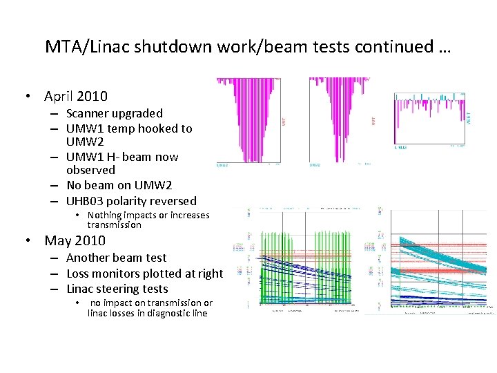
MTA/Linac shutdown work/beam tests continued … • April 2010 – Scanner upgraded – UMW 1 temp hooked to UMW 2 – UMW 1 H- beam now observed – No beam on UMW 2 – UHB 03 polarity reversed • Nothing impacts or increases transmission • May 2010 – Another beam test – Loss monitors plotted at right – Linac steering tests • no impact on transmission or linac losses in diagnostic line
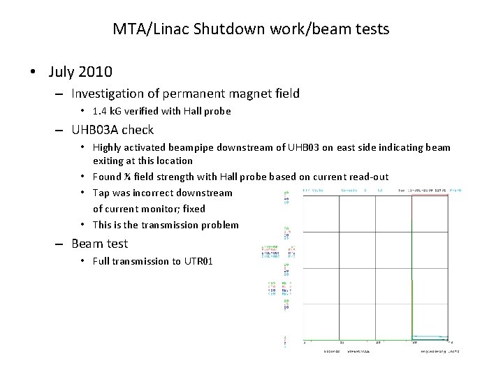
MTA/Linac Shutdown work/beam tests • July 2010 – Investigation of permanent magnet field • 1. 4 k. G verified with Hall probe – UHB 03 A check • Highly activated beampipe downstream of UHB 03 on east side indicating beam exiting at this location • Found ¼ field strength with Hall probe based on current read-out • Tap was incorrect downstream of current monitor; fixed • This is the transmission problem – Beam test • Full transmission to UTR 01
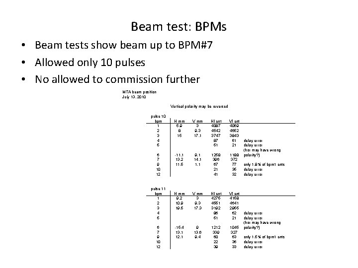
Beam test: BPMs • Beam tests show beam up to BPM#7 • Allowed only 10 pulses • No allowed to commission further MTA beam position July 13, 2010 Vertical polarity may be reversed pulse 10 bpm 1 2 3 4 5 6 7 9 10 12 pulse 11 bpm 1 2 3 4 5 6 7 9 10 12 H mm 5. 9 8 15 V mm 3 9. 3 17. 1 HI cnt 4087 4542 3747 87 51 VI cnt 4069 4652 3843 61 21 -11. 1 13. 2 11. 5 9. 1 14. 1 1258 396 67 21 41 1188 372 77 35 32 H mm 9. 2 10. 9 19. 5 V mm 3 9. 3 17. 3 HI cnt 4275 4551 3192 86 51 VI cnt 4158 4641 2955 62 21 1212 339 60 22 39 1045 327 63 36 33 -15. 4 13. 1 12. 1 9 13. 6 9. 4 delay error (hor may have wrong polarity? ) only 1. 8% of bpm 1 cnts delay error (hor may have wrong polarity? ) only 1. 5% of bpm 1 cnts delay error
Status of Shielding Assessment • Final Revisions submitted 11/2/2010 – Sign-off by SA committee anticipated this week – Goes to 7 th floor and then DOE for approval • Commissioning – Beamline can be transported to 1 st beam stop immediately after approval – will request preliminary beam prior to full approval • Fully parasitic operation (with the exception of Linac studies or NTF) eliminates scheduling conflicts with HEP – Beam to experiment requires • Full shielding installed in hall – Service building shield wall – Poly in penetrations
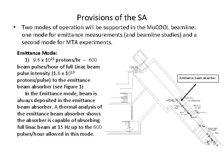
Provisions of the SA • Two modes of operation will be supported in the Mu. COOL beamline: one mode for emittance measurements (and beamline studies) and a second mode for MTA experiments. Emittance Mode: 1) 9. 6 x 10¹⁵ protons/hr – 600 beam pulses/hour of full Linac beam pulse intensity (1. 6 x 10¹³ protons/pulse) to the emittance beam absorber (see Figure 1) In the Emittance mode, beam is always deposited in the emittance beam absorber. A thermal analysis of the emittance beam absorber shows the absorber is capable of absorbing full linac beam at 15 Hz up to the 600 pulses/hour allowed in this mode. Emittance beam absorber
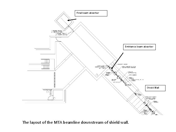
Final beam absorber Emittance beam absorber Shield Wall The layout of the MTA beamline downstream of shield wall.
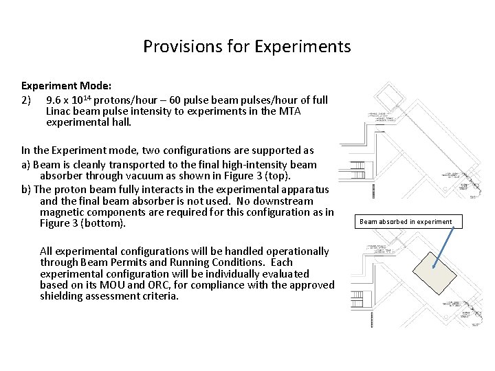
Provisions for Experiments Experiment Mode: 2) 9. 6 x 10¹⁴ protons/hour – 60 pulse beam pulses/hour of full Linac beam pulse intensity to experiments in the MTA experimental hall. In the Experiment mode, two configurations are supported as a) Beam is cleanly transported to the final high-intensity beam absorber through vacuum as shown in Figure 3 (top). b) The proton beam fully interacts in the experimental apparatus and the final beam absorber is not used. No downstream magnetic components are required for this configuration as in Figure 3 (bottom). All experimental configurations will be handled operationally through Beam Permits and Running Conditions. Each experimental configuration will be individually evaluated based on its MOU and ORC, for compliance with the approved shielding assessment criteria. Beam absorbed in experiment
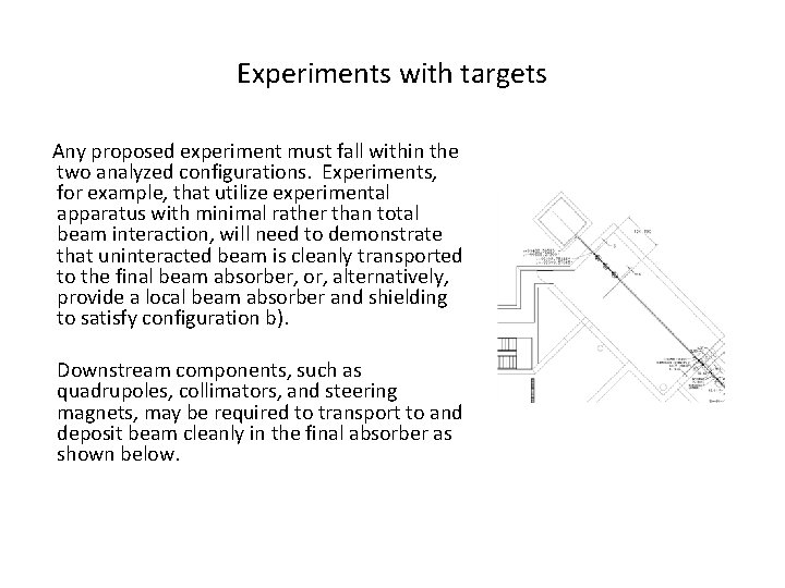
Experiments with targets Any proposed experiment must fall within the two analyzed configurations. Experiments, for example, that utilize experimental apparatus with minimal rather than total beam interaction, will need to demonstrate that uninteracted beam is cleanly transported to the final beam absorber, or, alternatively, provide a local beam absorber and shielding to satisfy configuration b). Downstream components, such as quadrupoles, collimators, and steering magnets, may be required to transport to and deposit beam cleanly in the final absorber as shown below.