
MSODPO Series Oscilloscopes Featurerich tools for debugging mixed
MSO/DPO Series Oscilloscopes Feature-rich tools for debugging mixed signal designs
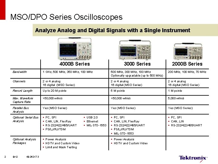
MSO/DPO Series Oscilloscopes Analyze Analog and Digital Signals with a Single Instrument 4000 B Series 2 3000 Series 2000 B Series Bandwidth 1 GHz, 500 MHz, 350 MHz, 100 MHz 500 MHz, 300 MHz, 100 MHz Optionally upgradable (up to 500 MHz) 200 MHz, 100 MHz, 70 MHz Channels 2 or 4 analog 16 digital (MSO Series) Record Length Up to 20 M points 5 M points 1 M points Max. Waveform Capture Rate >50, 000 wfm/s 5, 000 wfm/s Parallel Bus Analysis Yes (MSO Series) Optional Serial Bus Analysis § § § § § I 2 C, SPI § CAN, LIN § RS-232/422/485/UART Optional Analysis Packages § Power Analysis § HDTV and Custom Video § Limit and Mask Testing 8/12 48 -26217 -3 I 2 C, SPI CAN, LIN, Flex. Ray RS-232/422/485/UART I 2 S/LJ/RJ/TDM § USB 2. 0 § Ethernet § MIL-STD-1553 I 2 C, SPI CAN, LIN, Flex. Ray RS-232/422/485/UART I 2 S/LJ/RJ/TDM MIL-STD-1553 § Power Analysis § HDTV and Custom Video
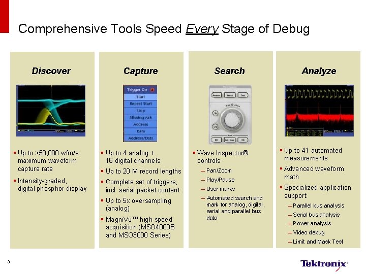
Comprehensive Tools Speed Every Stage of Debug Discover Capture § Up to >50, 000 wfm/s maximum waveform capture rate § Up to 4 analog + 16 digital channels § Up to 20 M record lengths – Pan/Zoom § Intensity-graded, digital phosphor display § Complete set of triggers, incl. serial packet content – Play/Pause § Up to 5 x oversampling (analog) – Automated search and mark for analog, digital, serial and parallel bus data § Magni. Vu™ high speed acquisition (MSO 4000 B and MSO 3000 Series) 3 Search § Wave Inspector® controls – User marks Analyze § Up to 41 automated measurements § Advanced waveform math § Specialized application support: – Parallel bus analysis – Serial bus analysis – Power analysis – Video debug – Limit and Mask Test
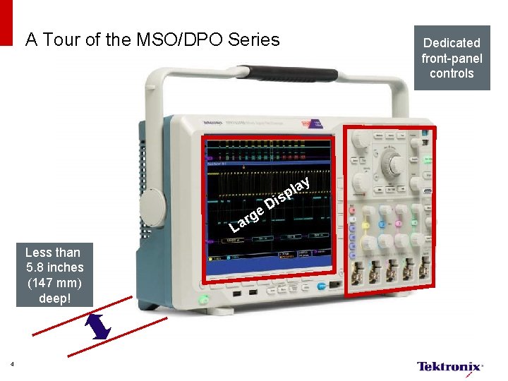
A Tour of the MSO/DPO Series Dedicated front-panel controls y a l p is D e rg a L Less than 5. 8 inches (147 mm) deep! 4
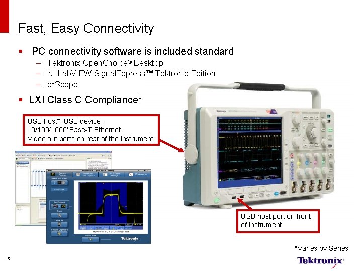
Fast, Easy Connectivity § PC connectivity software is included standard – Tektronix Open. Choice® Desktop – NI Lab. VIEW Signal. Express™ Tektronix Edition – e*Scope § LXI Class C Compliance* USB host*, USB device, 10/1000*Base-T Ethernet, Video out ports on rear of the instrument USB host port on front of instrument *Varies by Series 5
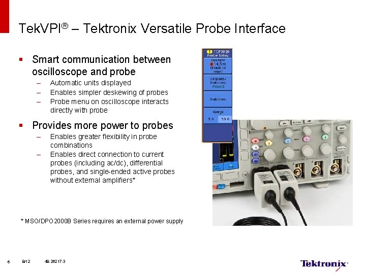
Tek. VPI® – Tektronix Versatile Probe Interface § Smart communication between oscilloscope and probe – – – Automatic units displayed Enables simpler deskewing of probes Probe menu on oscilloscope interacts directly with probe § Provides more power to probes – – Enables greater flexibility in probe combinations Enables direct connection to current probes (including ac/dc), differential probes, and single-ended active probes without external amplifiers* * MSO/DPO 2000 B Series requires an external power supply 6 8/12 48 -26217 -3
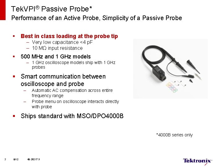
Tek. VPI® Passive Probe* Performance of an Active Probe, Simplicity of a Passive Probe § Best in class loading at the probe tip – Very low capacitance <4 p. F – 10 MΩ input resistance § 500 MHz and 1 GHz models – 1 GHz oscilloscope models ship with 1 GHz probes § Smart communication between oscilloscope and probe – – Automatic AC compensation across entire frequency range Probe menu on oscilloscope interacts directly with probe § Ships standard with MSO/DPO 4000 B *4000 B series only 7 8/12 48 -26217 -3
Tools to Speed Every Stage of Debug
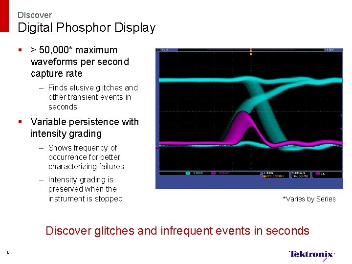
Discover Digital Phosphor Display § > 50, 000* maximum waveforms per second capture rate – Finds elusive glitches and other transient events in seconds § Variable persistence with intensity grading – Shows frequency of occurrence for better characterizing failures – Intensity grading is preserved when the instrument is stopped *Varies by Series Discover glitches and infrequent events in seconds 9
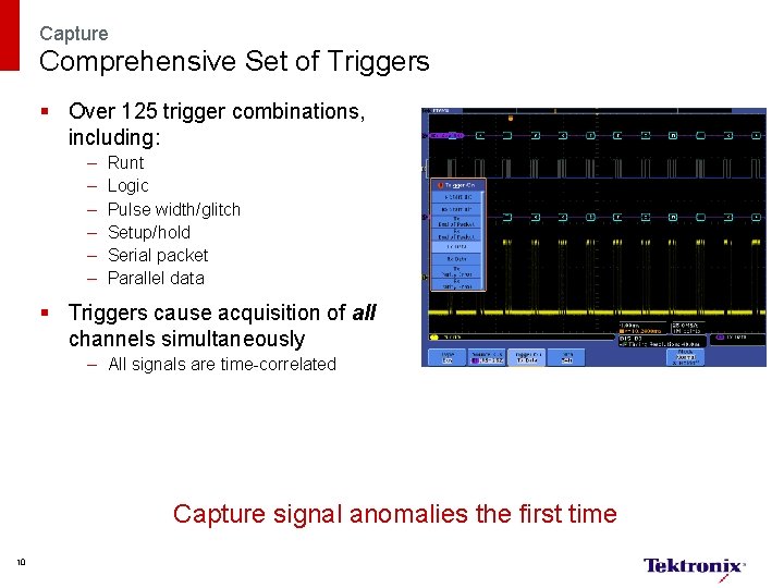
Capture Comprehensive Set of Triggers § Over 125 trigger combinations, including: – – – Runt Logic Pulse width/glitch Setup/hold Serial packet Parallel data § Triggers cause acquisition of all channels simultaneously – All signals are time-correlated Capture signal anomalies the first time 10
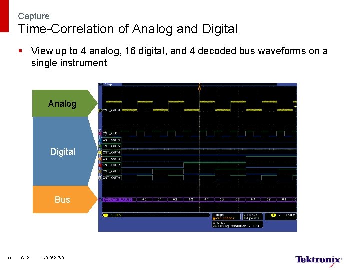
Capture Time-Correlation of Analog and Digital § View up to 4 analog, 16 digital, and 4 decoded bus waveforms on a single instrument Analog Digital Bus 11 8/12 48 -26217 -3
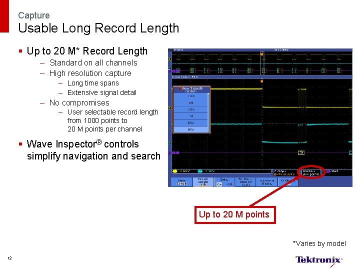
Capture Usable Long Record Length § Up to 20 M* Record Length – Standard on all channels – High resolution capture – Long time spans – Extensive signal detail – No compromises – User selectable record length from 1000 points to 20 M points per channel § Wave Inspector® controls simplify navigation and search Up to 20 M points *Varies by model 12
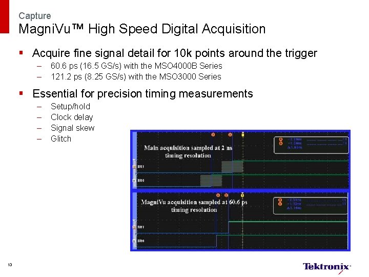
Capture Magni. Vu™ High Speed Digital Acquisition § Acquire fine signal detail for 10 k points around the trigger – – 60. 6 ps (16. 5 GS/s) with the MSO 4000 B Series 121. 2 ps (8. 25 GS/s) with the MSO 3000 Series § Essential for precision timing measurements – – 13 Setup/hold Clock delay Signal skew Glitch
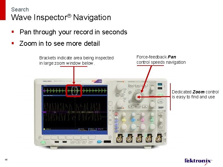
Search Wave Inspector® Navigation § Pan through your record in seconds § Zoom in to see more detail Brackets indicate area being inspected in large zoom window below. Force-feedback Pan control speeds navigation Dedicated Zoom control is easy to find and use 14
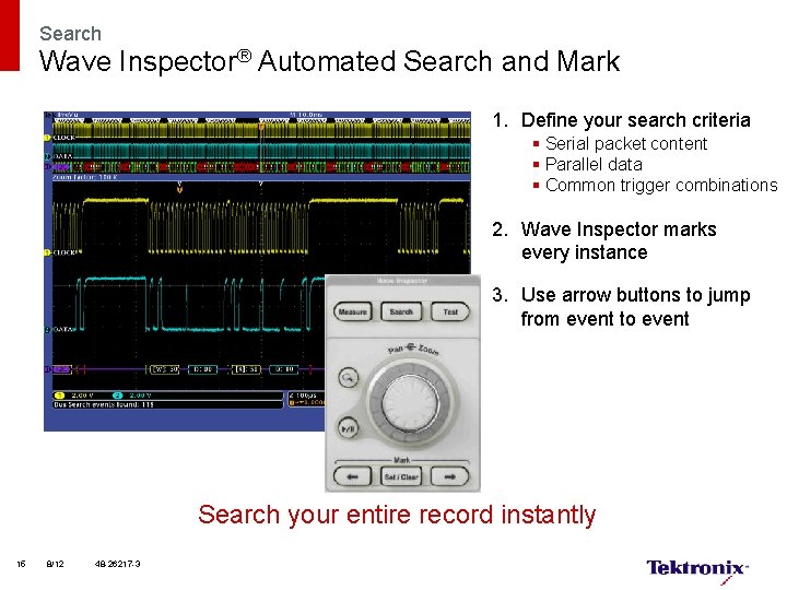
Search Wave Inspector® Automated Search and Mark 1. Define your search criteria § Serial packet content § Parallel data § Common trigger combinations 2. Wave Inspector marks every instance 3. Use arrow buttons to jump from event to event Search your entire record instantly 15 8/12 48 -26217 -3
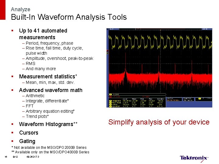
Analyze Built-In Waveform Analysis Tools § Up to 41 automated measurements – Period, frequency, phase – Rise time, fall time, duty cycle, pulse width – Amplitude, overshoot, peak-to-peak – RMS – And many more § Measurement statistics* – Mean, min, max, std. dev. § Advanced waveform math – – – Arithmetic Integrate, differentiate* FFT Arbitrary equation editing* Trend plots* § Waveform Histograms** § Cursors § Gating * Not available on the MSO/DPO 2000 B Series ** Available only on the MSO/DPO 4000 B Series 16 8/12 48 -26217 -3 Simplify analysis of your device
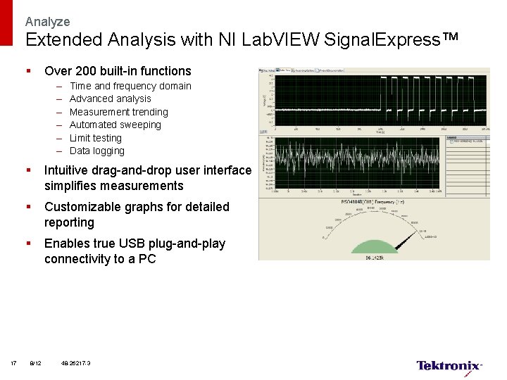
Analyze Extended Analysis with NI Lab. VIEW Signal. Express™ § Over 200 built-in functions – – – Time and frequency domain Advanced analysis Measurement trending Automated sweeping Limit testing Data logging § Intuitive drag-and-drop user interface simplifies measurements § Customizable graphs for detailed reporting § Enables true USB plug-and-play connectivity to a PC 17 8/12 48 -26217 -3
Serial Bus Triggering and Analysis
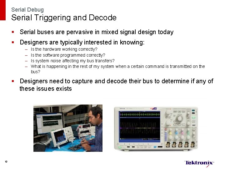
Serial Debug Serial Triggering and Decode § Serial buses are pervasive in mixed signal design today § Designers are typically interested in knowing: – – Is the hardware working correctly? Is the software programmed correctly? Is system noise affecting my bus transfers? What is happening in the rest of my system when a certain command is transmitted on the bus? § Designers need to capture and decode their bus to determine if any of these issues exists 19
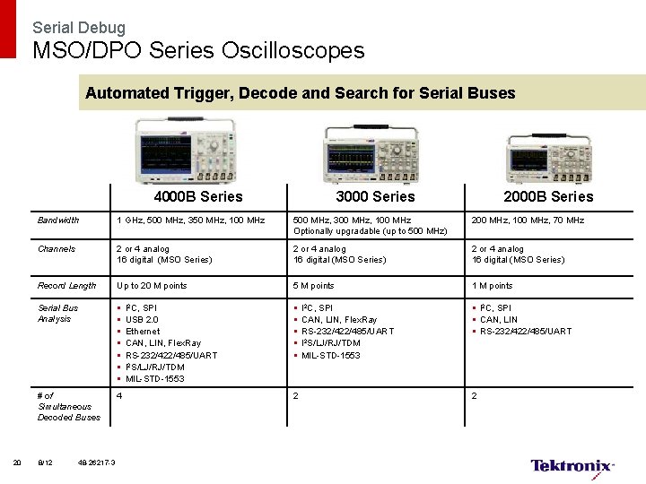
Serial Debug MSO/DPO Series Oscilloscopes Automated Trigger, Decode and Search for Serial Buses 4000 B Series 20 3000 Series 2000 B Series Bandwidth 1 GHz, 500 MHz, 350 MHz, 100 MHz 500 MHz, 300 MHz, 100 MHz Optionally upgradable (up to 500 MHz) 200 MHz, 100 MHz, 70 MHz Channels 2 or 4 analog 16 digital (MSO Series) Record Length Up to 20 M points 5 M points 1 M points Serial Bus Analysis § § § § I 2 C, SPI § CAN, LIN § RS-232/422/485/UART # of Simultaneous Decoded Buses 4 8/12 48 -26217 -3 I 2 C, SPI USB 2. 0 Ethernet CAN, LIN, Flex. Ray RS-232/422/485/UART I 2 S/LJ/RJ/TDM MIL-STD-1553 2 I 2 C, SPI CAN, LIN, Flex. Ray RS-232/422/485/UART I 2 S/LJ/RJ/TDM MIL-STD-1553 2
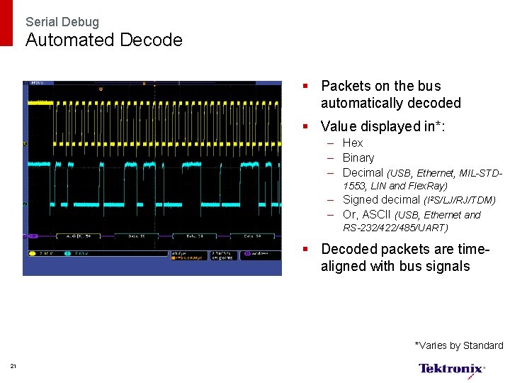
Serial Debug Automated Decode § Packets on the bus automatically decoded § Value displayed in*: – Hex – Binary – Decimal (USB, Ethernet, MIL-STD 1553, LIN and Flex. Ray) – Signed decimal (I 2 S/LJ/RJ/TDM) – Or, ASCII (USB, Ethernet and RS-232/422/485/UART) § Decoded packets are timealigned with bus signals *Varies by Standard 21
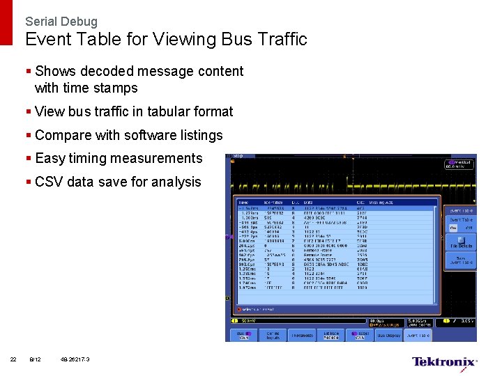
Serial Debug Event Table for Viewing Bus Traffic § Shows decoded message content with time stamps § View bus traffic in tabular format § Compare with software listings § Easy timing measurements § CSV data save for analysis 22 8/12 48 -26217 -3
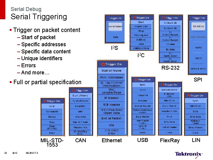
Serial Debug Serial Triggering § Trigger on packet content – Start of packet – Specific addresses – Specific data content – Unique identifiers – Errors – And more… I 2 S I 2 C RS-232 SPI § Full or partial specification MIL-STD 1553 23 8/12 48 -26217 -3 CAN Ethernet USB Flex. Ray LIN
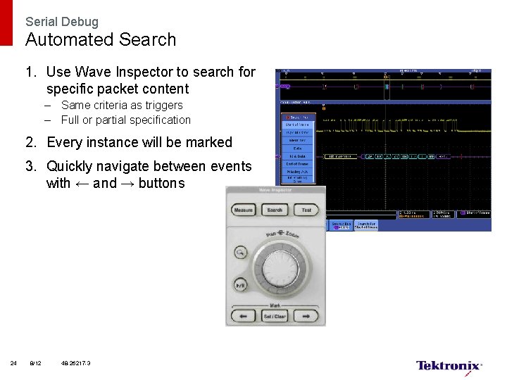
Serial Debug Automated Search 1. Use Wave Inspector to search for specific packet content – Same criteria as triggers – Full or partial specification 2. Every instance will be marked 3. Quickly navigate between events with ← and → buttons 24 8/12 48 -26217 -3
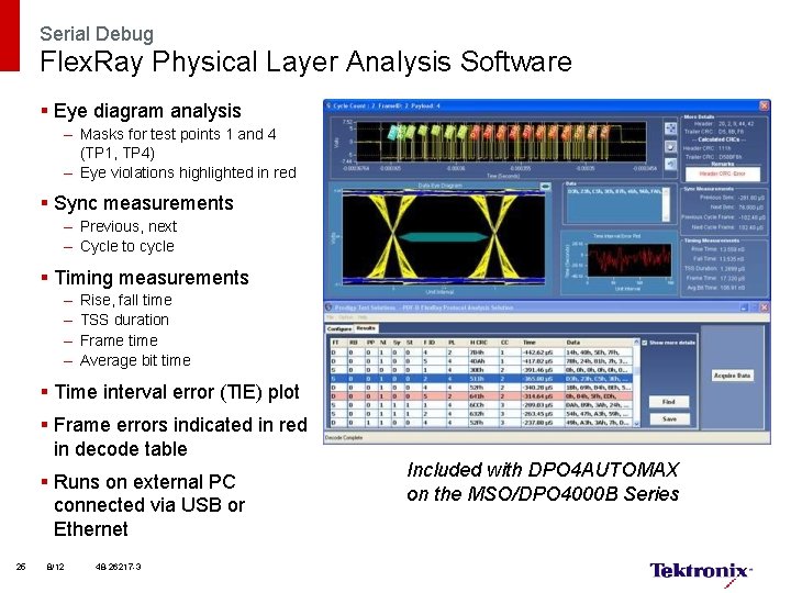
Serial Debug Flex. Ray Physical Layer Analysis Software § Eye diagram analysis – Masks for test points 1 and 4 (TP 1, TP 4) – Eye violations highlighted in red § Sync measurements – Previous, next – Cycle to cycle § Timing measurements – – Rise, fall time TSS duration Frame time Average bit time § Time interval error (TIE) plot § Frame errors indicated in red in decode table § Runs on external PC connected via USB or Ethernet 25 8/12 48 -26217 -3 Included with DPO 4 AUTOMAX on the MSO/DPO 4000 B Series
Mixed Signal Design and Analysis
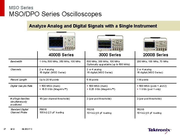
MSO Series MSO/DPO Series Oscilloscopes Analyze Analog and Digital Signals with a Single Instrument 4000 B Series 27 3000 Series 2000 B Series Bandwidth 1 GHz, 500 MHz, 350 MHz, 100 MHz 500 MHz, 300 MHz, 100 MHz Optionally upgradable (up to 500 MHz) 200 MHz, 100 MHz, 70 MHz Channels 2 or 4 analog 16 digital (MSO Series) Record Length Up to 20 M points 5 M points 1 M points Digital Sample Rate § 500 MS/s (main) § 16. 5 GS/s (Magni. Vu™) § 500 MS/s (main) § 8. 25 GS/s (Magni. Vu™) § 500 MS/s (pods 1 and 2) § 1 GS/s (pod 1 only) # of logic families simultaneously monitored 16 (per-channel thresholds) 2 (per-pod thresholds) Standard Digital Channel Probe P 6616 100 kΩ || 3 p. F loading P 6316 101 kΩ || 8 p. F loading 8/12 48 -26217 -3
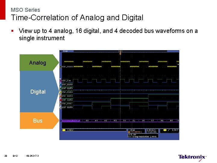
MSO Series Time-Correlation of Analog and Digital § View up to 4 analog, 16 digital, and 4 decoded bus waveforms on a single instrument Analog Digital Bus 28 8/12 48 -26217 -3
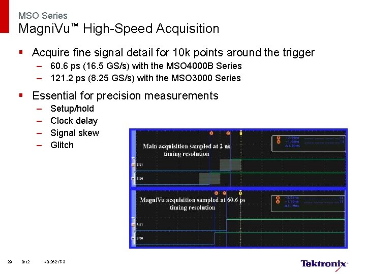
MSO Series Magni. Vu™ High-Speed Acquisition § Acquire fine signal detail for 10 k points around the trigger – 60. 6 ps (16. 5 GS/s) with the MSO 4000 B Series – 121. 2 ps (8. 25 GS/s) with the MSO 3000 Series § Essential for precision measurements – – 29 8/12 Setup/hold Clock delay Signal skew Glitch 48 -26217 -3
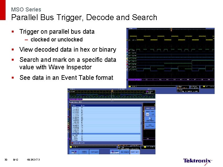
MSO Series Parallel Bus Trigger, Decode and Search § Trigger on parallel bus data – clocked or unclocked § View decoded data in hex or binary § Search and mark on a specific data value with Wave Inspector § See data in an Event Table format 30 8/12 48 -26217 -3
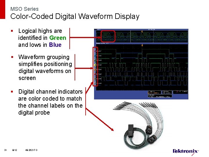
MSO Series Color-Coded Digital Waveform Display § Logical highs are identified in Green and lows in Blue § Waveform grouping simplifies positioning digital waveforms on screen § Digital channel indicators are color coded to match the channel labels on the digital probe 31 8/12 48 -26217 -3
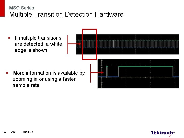
MSO Series Multiple Transition Detection Hardware § If multiple transitions are detected, a white edge is shown § More information is available by zooming in or using a faster sample rate 32 8/12 48 -26217 -3
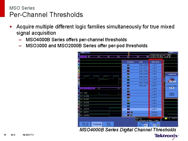
MSO Series Per-Channel Thresholds § Acquire multiple different logic families simultaneously for true mixed signal acquisition – MSO 4000 B Series offers per-channel thresholds – MSO 3000 and MSO 2000 B Series offer per-pod thresholds MSO 4000 B Series Digital Channel Thresholds 33 8/12 48 -26217 -3
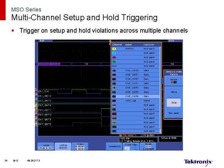
MSO Series Multi-Channel Setup and Hold Triggering § Trigger on setup and hold violations across multiple channels 34 8/12 48 -26217 -3
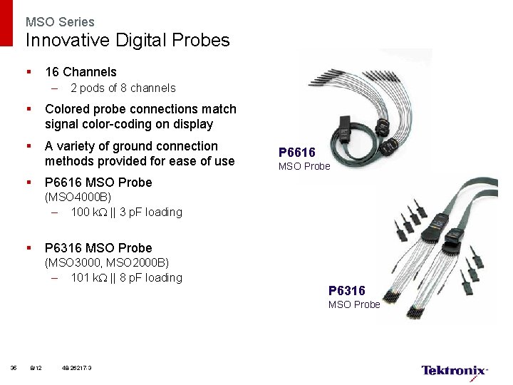
MSO Series Innovative Digital Probes § 16 Channels – 2 pods of 8 channels § Colored probe connections match signal color-coding on display § A variety of ground connection methods provided for ease of use § P 6616 MSO Probe (MSO 4000 B) – 100 k || 3 p. F loading § P 6316 MSO Probe (MSO 3000, MSO 2000 B) – 101 k || 8 p. F loading P 6316 MSO Probe 35 8/12 48 -26217 -3
Additional Application Support
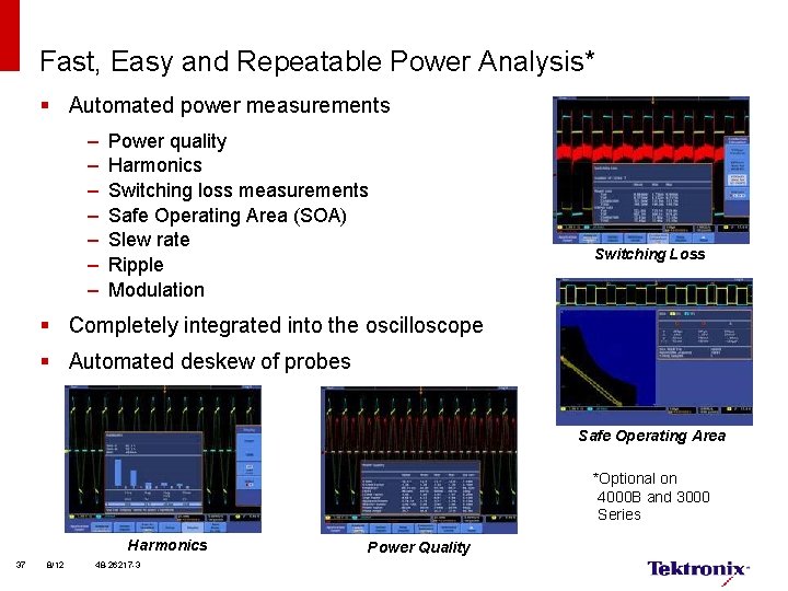
Fast, Easy and Repeatable Power Analysis* § Automated power measurements – – – – Power quality Harmonics Switching loss measurements Safe Operating Area (SOA) Slew rate Ripple Modulation Switching Loss § Completely integrated into the oscilloscope § Automated deskew of probes Safe Operating Area *Optional on 4000 B and 3000 Series Harmonics 37 8/12 48 -26217 -3 Power Quality
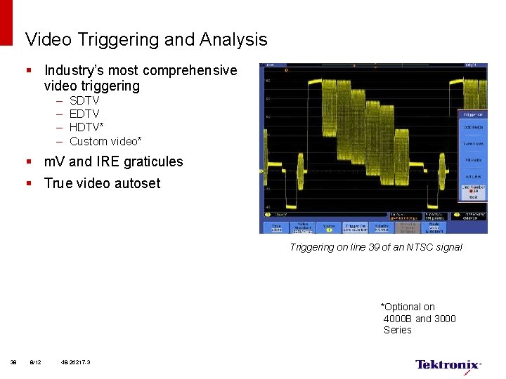
Video Triggering and Analysis § Industry’s most comprehensive video triggering – – SDTV EDTV HDTV* Custom video* § m. V and IRE graticules § True video autoset Triggering on line 39 of an NTSC signal *Optional on 4000 B and 3000 Series 38 8/12 48 -26217 -3
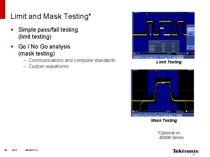
Limit and Mask Testing* § Simple pass/fail testing (limit testing) § Go / No Go analysis (mask testing) – Communications and computer standards – Custom waveforms Limit Testing Mask Testing *Optional on 4000 B Series 39 8/12 48 -26217 -3
A Complete Solution
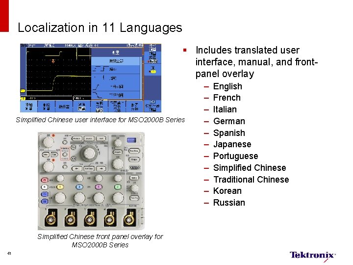
Localization in 11 Languages § Includes translated user interface, manual, and frontpanel overlay Simplified Chinese user interface for MSO 2000 B Series Simplified Chinese front panel overlay for MSO 2000 B Series 41 – – – English French Italian German Spanish Japanese Portuguese Simplified Chinese Traditional Chinese Korean Russian
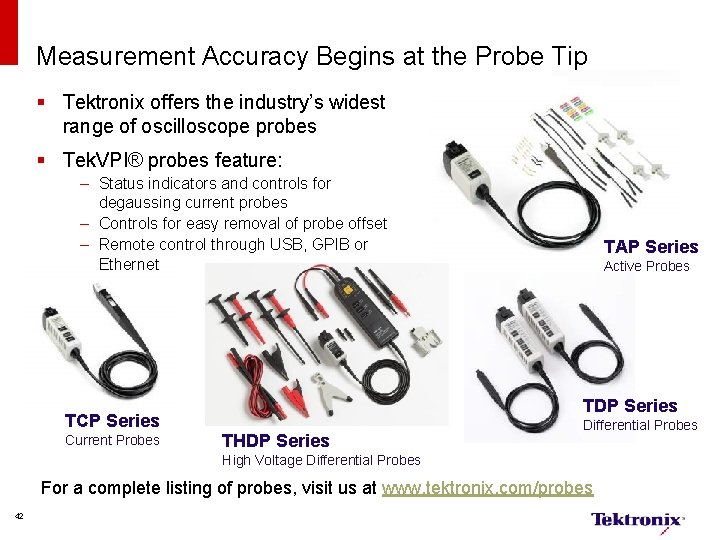
Measurement Accuracy Begins at the Probe Tip § Tektronix offers the industry’s widest range of oscilloscope probes § Tek. VPI® probes feature: – Status indicators and controls for degaussing current probes – Controls for easy removal of probe offset – Remote control through USB, GPIB or Ethernet Active Probes TDP Series TCP Series Current Probes TAP Series THDP Series Differential Probes High Voltage Differential Probes For a complete listing of probes, visit us at www. tektronix. com/probes 42
Maintain Your Oscilloscope at Peak Performance § Standard warranty on all parts and labor, excluding probes § Repair and calibration plans are available to extend your coverage Silver Care Plan – Repair of the product problem – Free shipping both ways* – Installation of all safety modifications and mandatory reliability modifications – Installation of firmware updates – Free Factory Certified calibration after each repair Factory Certified Calibration Gold Care Plan – Loaner of equal or higher performance during product repair – Typical downtime of two days or less – Coverage for customer caused ESD/EOS damage – Priority access to customer support – Free Factory Certified Calibration after repair – All the benefits of Silver Care Plan 43 January 2012 – Full calibration with adjustments – Calibration certificate or Certificate of Compliance – Free shipping both ways* – Installation of all safety modifications and mandatory reliability modifications – Installation of firmware updates – Available with complete calibration data Platinum Care Plan – Customized program – Provision for uniquely customized products – On-site calibration, expedited repairs, dedicated spare parts, priority access to customer support *Within end-user country
A Detailed Family Comparison
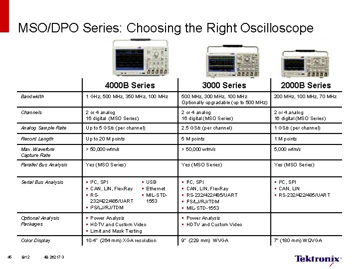
MSO/DPO Series: Choosing the Right Oscilloscope 4000 B Series 45 3000 Series 2000 B Series Bandwidth 1 GHz, 500 MHz, 350 MHz, 100 MHz 500 MHz, 300 MHz, 100 MHz Optionally upgradable (up to 500 MHz) 200 MHz, 100 MHz, 70 MHz Channels 2 or 4 analog 16 digital (MSO Series) Analog Sample Rate Up to 5 GS/s (per channel) 2. 5 GS/s (per channel) 1 GS/s (per channel) Record Length Up to 20 M points 5 M points 1 M points Max. Waveform Capture Rate > 50, 000 wfm/s 5, 000 wfm/s Parallel Bus Analysis Yes (MSO Series) Serial Bus Analysis § I 2 C, SPI § CAN, LIN, Flex. Ray § RS 232/422/485/UART § I 2 S/LJ/RJ/TDM § § § I 2 C, SPI § CAN, LIN § RS-232/422/485/UART Optional Analysis Packages § Power Analysis § HDTV and Custom Video § Limit and Mask Testing § Power Analysis § HDTV and Custom Video Color Display 10. 4” (264 mm) XGA resolution 9” (229 mm) WVGA 8/12 48 -26217 -3 § USB § Ethernet § MIL-STD 1553 I 2 C, SPI CAN, LIN, Flex. Ray RS-232/422/485/UART I 2 S/LJ/RJ/TDM MIL-STD-1553 7” (180 mm) WQVGA
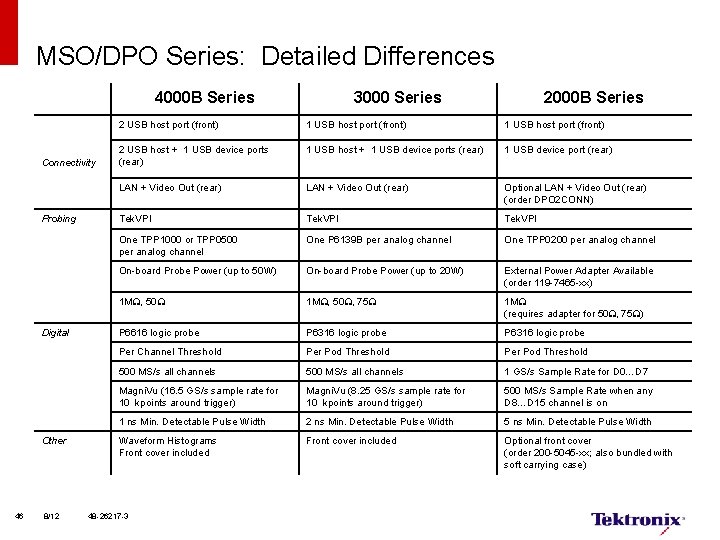
MSO/DPO Series: Detailed Differences 4000 B Series Connectivity Probing Digital Other 46 8/12 3000 Series 2000 B Series 2 USB host port (front) 1 USB host port (front) 2 USB host + 1 USB device ports (rear) 1 USB device port (rear) LAN + Video Out (rear) Optional LAN + Video Out (rear) (order DPO 2 CONN) Tek. VPI One TPP 1000 or TPP 0500 per analog channel One P 6139 B per analog channel One TPP 0200 per analog channel On-board Probe Power (up to 50 W) On-board Probe Power (up to 20 W) External Power Adapter Available (order 119 -7465 -xx) 1 M , 50 , 75 1 M (requires adapter for 50 , 75 ) P 6616 logic probe P 6316 logic probe Per Channel Threshold Per Pod Threshold 500 MS/s all channels 1 GS/s Sample Rate for D 0…D 7 Magni. Vu (16. 5 GS/s sample rate for 10 kpoints around trigger) Magni. Vu (8. 25 GS/s sample rate for 10 kpoints around trigger) 500 MS/s Sample Rate when any D 8…D 15 channel is on 1 ns Min. Detectable Pulse Width 2 ns Min. Detectable Pulse Width 5 ns Min. Detectable Pulse Width Waveform Histograms Front cover included Optional front cover (order 200 -5045 -xx; also bundled with soft carrying case) 48 -26217 -3
MSO/DPO 4000 B Series Ordering Information 47
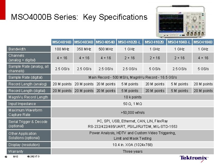
MSO 4000 B Series: Key Specifications MSO 4014 B MSO 4034 B MSO 4054 B MSO 4102 B-L Bandwidth Channels (analog + digital) Sample Rate (analog, all channels) Sample Rate (digital) MSO 4104 B-L MSO 4104 B 100 MHz 350 MHz 500 MHz 1 GHz 4 + 16 2 + 16 4 + 16 2. 5 GS/s 5 GS/s 2. 5 GS/s Main Record - 500 MS/s, Magni. Vu Record - 16. 5 GS/s Record Length (analog) 20 M points 5 M points 20 M points Record Length (digital) 20 M points 5 M points 20 M points Magni. Vu Record Length 10 k points Input Impedance 50 Ω, 1 MΩ Maximum Waveform Capture Rate Serial Trigger & Decode (optional) >50, 000 wfm/s I 2 C, SPI, USB, Ethernet, CAN, LIN, Flex. Ray RS-232/422/485/UART, I 2 S/LJ/RJ/TDM, MIL-STD-1553 Other Application Solutions (optional) Power Analysis, HDTV and Custom Video Triggering, Limit and Mask Testing Display (resolution) 10. 4 in. XGA (1024 x 768) Warranty 48 MSO 4102 B 8/12 Three years 48 -26217 -3
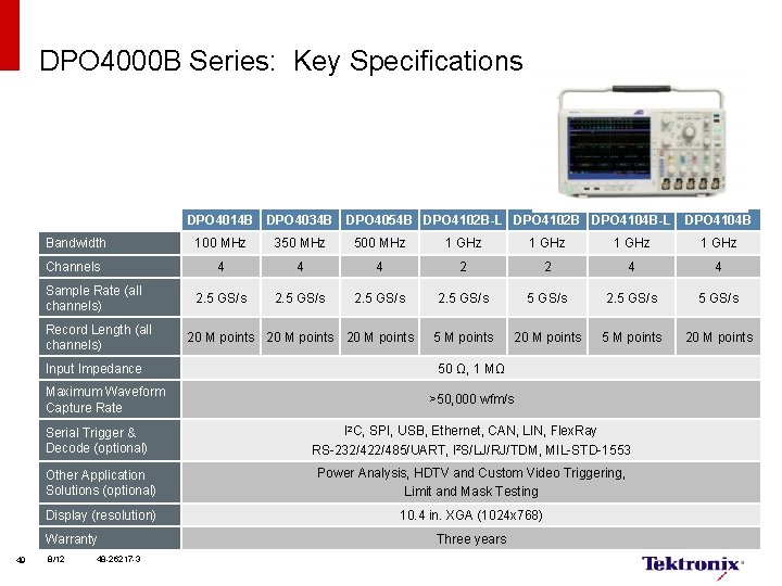
DPO 4000 B Series: Key Specifications DPO 4014 B DPO 4034 B DPO 4104 B Bandwidth 100 MHz 350 MHz 500 MHz 1 GHz Channels 4 4 4 2 2 4 4 2. 5 GS/s 5 GS/s 2. 5 GS/s 5 M points 20 M points Sample Rate (all channels) Record Length (all channels) Input Impedance Maximum Waveform Capture Rate Serial Trigger & Decode (optional) 20 M points 50 Ω, 1 MΩ >50, 000 wfm/s I 2 C, SPI, USB, Ethernet, CAN, LIN, Flex. Ray RS-232/422/485/UART, I 2 S/LJ/RJ/TDM, MIL-STD-1553 Other Application Solutions (optional) Power Analysis, HDTV and Custom Video Triggering, Limit and Mask Testing Display (resolution) 10. 4 in. XGA (1024 x 768) Warranty 49 DPO 4054 B DPO 4102 B-L DPO 4102 B DPO 4104 B-L 8/12 48 -26217 -3 Three years
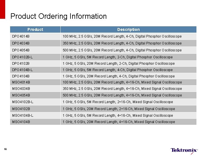
Product Ordering Information Product 50 Description DPO 4014 B 100 MHz, 2. 5 GS/s, 20 M Record Length, 4 -Ch, Digital Phosphor Oscilloscope DPO 4034 B 350 MHz, 2. 5 GS/s, 20 M Record Length, 4 -Ch, Digital Phosphor Oscilloscope DPO 4054 B 500 MHz, 2. 5 GS/s, 20 M Record Length, 4 -Ch, Digital Phosphor Oscilloscope DPO 4102 B-L 1 GHz, 5 GS/s, 5 M Record Length, 2 -Ch, Digital Phosphor Oscilloscope DPO 4102 B 1 GHz, 5 GS/s, 20 M Record Length, 2 -Ch, Digital Phosphor Oscilloscope DPO 4104 B-L 1 GHz, 5 GS/s, 5 M Record Length, 4 -Ch, Digital Phosphor Oscilloscope DPO 4104 B 1 GHz, 5 GS/s, 20 M Record Length, 4 -Ch, Digital Phosphor Oscilloscope MSO 4014 B 100 MHz, 2. 5 GS/s, 20 M Record Length, 4+16 -Ch, Mixed Signal Oscilloscope MSO 4034 B 350 MHz, 2. 5 GS/s, 20 M Record Length, 4+16 -Ch, Mixed Signal Oscilloscope MSO 4054 B 500 MHz, 2. 5 GS/s, 20 M Record Length, 4+16 -Ch, Mixed Signal Oscilloscope MSO 4102 B-L 1 GHz, 5 GS/s, 5 M Record Length, 2+16 -Ch, Mixed Signal Oscilloscope MSO 4102 B 1 GHz, 5 GS/s, 20 M Record Length, 2+16 -Ch, Mixed Signal Oscilloscope MSO 4104 B-L 1 GHz, 5 GS/s, 5 M Record Length, 4+16 -Ch, Mixed Signal Oscilloscope MSO 4104 B 1 GHz, 5 GS/s, 20 M Record Length, 4+16 -Ch, Mixed Signal Oscilloscope
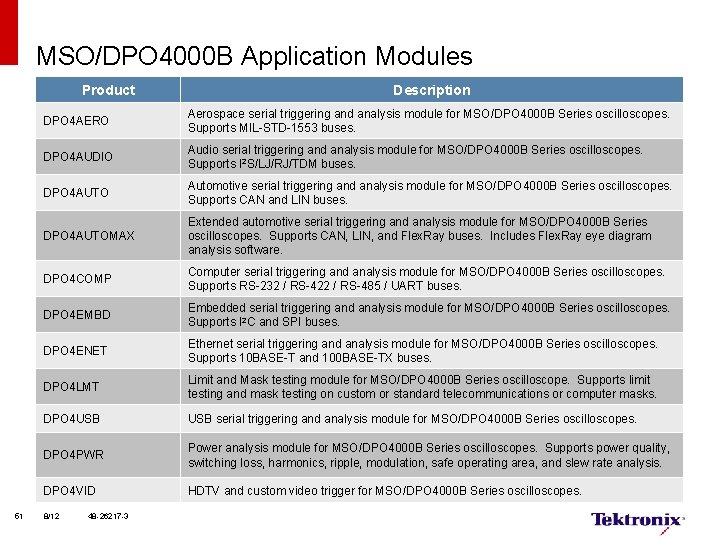
MSO/DPO 4000 B Application Modules Product 51 Description DPO 4 AERO Aerospace serial triggering and analysis module for MSO/DPO 4000 B Series oscilloscopes. Supports MIL-STD-1553 buses. DPO 4 AUDIO Audio serial triggering and analysis module for MSO/DPO 4000 B Series oscilloscopes. Supports I 2 S/LJ/RJ/TDM buses. DPO 4 AUTO Automotive serial triggering and analysis module for MSO/DPO 4000 B Series oscilloscopes. Supports CAN and LIN buses. DPO 4 AUTOMAX Extended automotive serial triggering and analysis module for MSO/DPO 4000 B Series oscilloscopes. Supports CAN, LIN, and Flex. Ray buses. Includes Flex. Ray eye diagram analysis software. DPO 4 COMP Computer serial triggering and analysis module for MSO/DPO 4000 B Series oscilloscopes. Supports RS-232 / RS-422 / RS-485 / UART buses. DPO 4 EMBD Embedded serial triggering and analysis module for MSO/DPO 4000 B Series oscilloscopes. Supports I 2 C and SPI buses. DPO 4 ENET Ethernet serial triggering and analysis module for MSO/DPO 4000 B Series oscilloscopes. Supports 10 BASE-T and 100 BASE-TX buses. DPO 4 LMT Limit and Mask testing module for MSO/DPO 4000 B Series oscilloscope. Supports limit testing and mask testing on custom or standard telecommunications or computer masks. DPO 4 USB serial triggering and analysis module for MSO/DPO 4000 B Series oscilloscopes. DPO 4 PWR Power analysis module for MSO/DPO 4000 B Series oscilloscopes. Supports power quality, switching loss, harmonics, ripple, modulation, safe operating area, and slew rate analysis. DPO 4 VID HDTV and custom video trigger for MSO/DPO 4000 B Series oscilloscopes. 8/12 48 -26217 -3
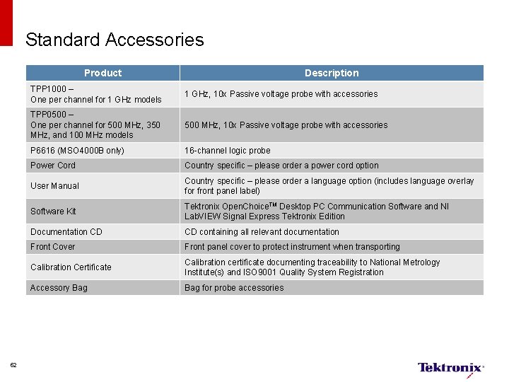
Standard Accessories Product 52 Description TPP 1000 – One per channel for 1 GHz models 1 GHz, 10 x Passive voltage probe with accessories TPP 0500 – One per channel for 500 MHz, 350 MHz, and 100 MHz models 500 MHz, 10 x Passive voltage probe with accessories P 6616 (MSO 4000 B only) 16 -channel logic probe Power Cord Country specific – please order a power cord option User Manual Country specific – please order a language option (includes language overlay for front panel label) Software Kit Tektronix Open. Choice. TM Desktop PC Communication Software and NI Lab. VIEW Signal Express Tektronix Edition Documentation CD CD containing all relevant documentation Front Cover Front panel cover to protect instrument when transporting Calibration Certificate Calibration certificate documenting traceability to National Metrology Institute(s) and ISO 9001 Quality System Registration Accessory Bag for probe accessories
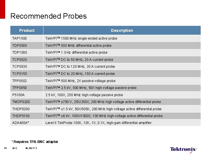
Recommended Probes Product Description TAP 1500 Tek. VPITM 1500 MHz single-ended active probe TDP 0500 Tek. VPITM 500 MHz differential active probe TDP 1000 Tek. VPITM 1 GHz differential active probe TCP 0020 Tek. VPITM DC to 50 MHz, 20 A current probe TCP 0030 Tek. VPITM DC to 120 MHz, 30 A current probe TCP 0150 Tek. VPITM DC to 20 MHz, 150 A current probe TPP 0502 Tek. VPITM 500 MHz, 2 X passive voltage probe TPP 0850 Tek. VPITM 2. 5 k. V, 800 MHz, 50 X high voltage passive probe P 5100 A 2. 5 k. V, 100 X, 250 MHz high voltage passive probe TMDP 0200 Tek. VPITM ± 750 V, 25 X/250 X, 200 MHz high voltage active differential probe THDP 0200 Tek. VPITM ± 1. 5 k. V, 50 X/500 X, 200 MHz high voltage active differential probe THDP 0100 Tek. VPITM ± 6 k. V, 100 X/1000 X, 100 MHz high voltage active differential probe ADA 400 A* Level II Tek. Probe 100 X, 1 X, 0. 1 X, high-gain differential amplifier * Requires TPA-BNC adapter 53 8/12 48 -26217 -3
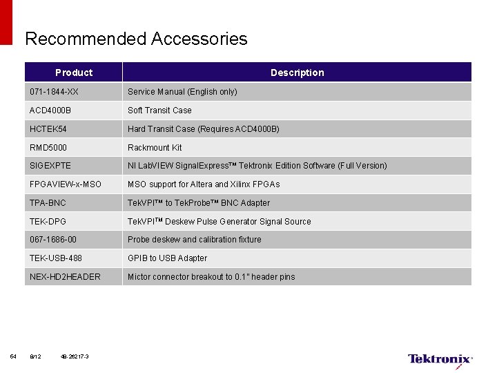
Recommended Accessories Product 54 Description 071 -1844 -XX Service Manual (English only) ACD 4000 B Soft Transit Case HCTEK 54 Hard Transit Case (Requires ACD 4000 B) RMD 5000 Rackmount Kit SIGEXPTE NI Lab. VIEW Signal. Express™ Tektronix Edition Software (Full Version) FPGAVIEW-x-MSO support for Altera and Xilinx FPGAs TPA-BNC Tek. VPI™ to Tek. Probe™ BNC Adapter TEK-DPG Tek. VPITM Deskew Pulse Generator Signal Source 067 -1686 -00 Probe deskew and calibration fixture TEK-USB-488 GPIB to USB Adapter NEX-HD 2 HEADER Mictor connector breakout to 0. 1” header pins 8/12 48 -26217 -3
MSO/DPO 3000 Series Ordering Information 55
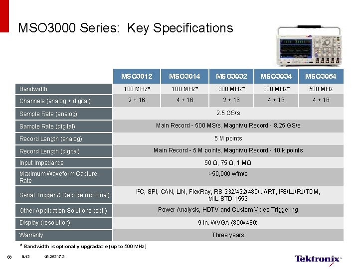
MSO 3000 Series: Key Specifications Bandwidth Channels (analog + digital) MSO 3012 MSO 3014 MSO 3032 MSO 3034 MSO 3054 100 MHz* 300 MHz* 500 MHz 2 + 16 4 + 16 Sample Rate (analog) 2. 5 GS/s Sample Rate (digital) Main Record - 500 MS/s, Magni. Vu Record - 8. 25 GS/s Record Length (analog) 5 M points Record Length (digital) Main Record - 5 M points, Magni. Vu Record - 10 k points 50 Ω, 75 Ω, 1 MΩ Input Impedance >50, 000 wfm/s Maximum Waveform Capture Rate Serial Trigger & Decode (optional) I 2 C, SPI, CAN, LIN, Flex. Ray, RS-232/422/485/UART, I 2 S/LJ/RJ/TDM, MIL-STD-1553 Other Application Solutions (opt. ) Power Analysis, HDTV and Custom Video Triggering Display (resolution) Warranty Three years * Bandwidth is optionally upgradable (up to 500 MHz) 56 8/12 9 in. WVGA (800 x 480) 48 -26217 -3
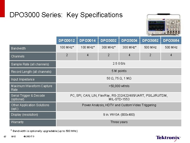
DPO 3000 Series: Key Specifications DPO 3012 DPO 3014 DPO 3032 DPO 3034 DPO 3052 DPO 3054 Bandwidth 100 MHz* 300 MHz* 500 MHz Channels 2 4 2 4 2. 5 GS/s Sample Rate (all channels) 5 M points Record Length (all channels) 50 Ω, 75 Ω, 1 MΩ Input Impedance >50, 000 wfm/s Maximum Waveform Capture Rate Serial Trigger & Decode (optional) I 2 C, SPI, CAN, LIN, Flex. Ray, RS-232/422/485/UART, I 2 S/LJ/RJ/TDM, MIL-STD-1553 Other Application Solutions (opt. ) Display (resolution) Warranty * Bandwidth is optionally upgradable (up to 500 MHz) 57 8/12 48 -26217 -3 Power Analysis, HDTV and Custom Video Triggering 9 in. WVGA (800 x 480) Three years
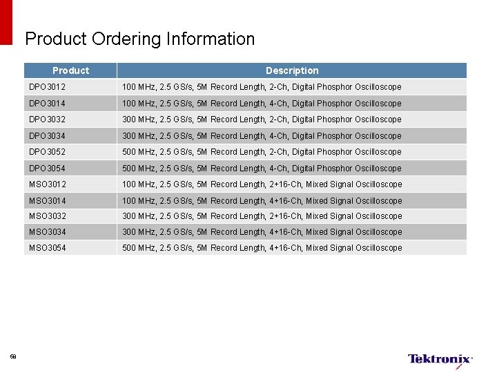
Product Ordering Information Product 58 Description DPO 3012 100 MHz, 2. 5 GS/s, 5 M Record Length, 2 -Ch, Digital Phosphor Oscilloscope DPO 3014 100 MHz, 2. 5 GS/s, 5 M Record Length, 4 -Ch, Digital Phosphor Oscilloscope DPO 3032 300 MHz, 2. 5 GS/s, 5 M Record Length, 2 -Ch, Digital Phosphor Oscilloscope DPO 3034 300 MHz, 2. 5 GS/s, 5 M Record Length, 4 -Ch, Digital Phosphor Oscilloscope DPO 3052 500 MHz, 2. 5 GS/s, 5 M Record Length, 2 -Ch, Digital Phosphor Oscilloscope DPO 3054 500 MHz, 2. 5 GS/s, 5 M Record Length, 4 -Ch, Digital Phosphor Oscilloscope MSO 3012 100 MHz, 2. 5 GS/s, 5 M Record Length, 2+16 -Ch, Mixed Signal Oscilloscope MSO 3014 100 MHz, 2. 5 GS/s, 5 M Record Length, 4+16 -Ch, Mixed Signal Oscilloscope MSO 3032 300 MHz, 2. 5 GS/s, 5 M Record Length, 2+16 -Ch, Mixed Signal Oscilloscope MSO 3034 300 MHz, 2. 5 GS/s, 5 M Record Length, 4+16 -Ch, Mixed Signal Oscilloscope MSO 3054 500 MHz, 2. 5 GS/s, 5 M Record Length, 4+16 -Ch, Mixed Signal Oscilloscope
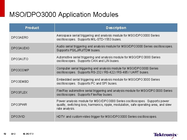
MSO/DPO 3000 Application Modules Product 59 Description DPO 3 AERO Aerospace serial triggering and analysis module for MSO/DPO 3000 Series oscilloscopes. Supports MIL-STD-1553 buses. DPO 3 AUDIO Audio serial triggering and analysis module for MSO/DPO 3000 Series oscilloscopes. Supports I 2 S/LJ/RJ/TDM buses. DPO 3 AUTO Automotive serial triggering and analysis module for MSO/DPO 3000 Series oscilloscopes. Supports CAN and LIN buses. DPO 3 COMP Computer serial triggering and analysis module for MSO/DPO 3000 Series oscilloscopes. Supports RS-232 / RS-422 / RS-485 / UART buses. DPO 3 EMBD Embedded serial triggering and analysis module for MSO/DPO 3000 Series oscilloscopes. Supports I 2 C and SPI buses. DPO 3 FLEX Flex. Ray automotive serial triggering and analysis module for MSO/DPO 3000 Series oscilloscopes. Supports Flex. Ray buses. DPO 3 PWR Power analysis module for MSO/DPO 3000 Series oscilloscopes. Supports power quality, switching loss, harmonics, ripple, modulation, safe operating area, and slew rate analysis. DPO 3 VID HDTV and custom video trigger for MSO/DPO 3000 Series oscilloscopes. 8/12 48 -26217 -3
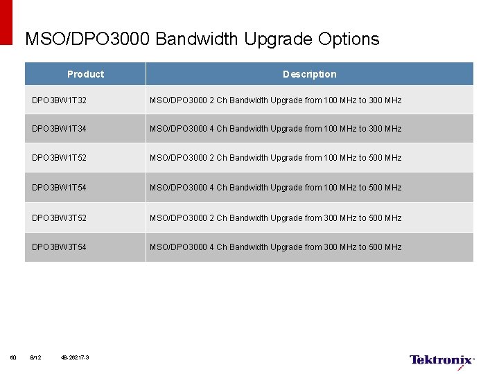
MSO/DPO 3000 Bandwidth Upgrade Options Product 60 Description DPO 3 BW 1 T 32 MSO/DPO 3000 2 Ch Bandwidth Upgrade from 100 MHz to 300 MHz DPO 3 BW 1 T 34 MSO/DPO 3000 4 Ch Bandwidth Upgrade from 100 MHz to 300 MHz DPO 3 BW 1 T 52 MSO/DPO 3000 2 Ch Bandwidth Upgrade from 100 MHz to 500 MHz DPO 3 BW 1 T 54 MSO/DPO 3000 4 Ch Bandwidth Upgrade from 100 MHz to 500 MHz DPO 3 BW 3 T 52 MSO/DPO 3000 2 Ch Bandwidth Upgrade from 300 MHz to 500 MHz DPO 3 BW 3 T 54 MSO/DPO 3000 4 Ch Bandwidth Upgrade from 300 MHz to 500 MHz 8/12 48 -26217 -3
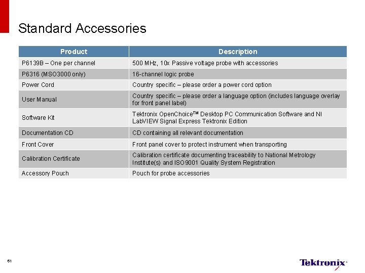
Standard Accessories Product 61 Description P 6139 B – One per channel 500 MHz, 10 x Passive voltage probe with accessories P 6316 (MSO 3000 only) 16 -channel logic probe Power Cord Country specific – please order a power cord option User Manual Country specific – please order a language option (includes language overlay for front panel label) Software Kit Tektronix Open. Choice. TM Desktop PC Communication Software and NI Lab. VIEW Signal Express Tektronix Edition Documentation CD CD containing all relevant documentation Front Cover Front panel cover to protect instrument when transporting Calibration Certificate Calibration certificate documenting traceability to National Metrology Institute(s) and ISO 9001 Quality System Registration Accessory Pouch for probe accessories
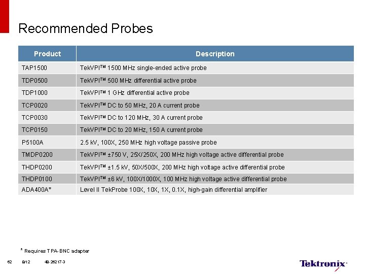
Recommended Probes Product Description TAP 1500 Tek. VPITM 1500 MHz single-ended active probe TDP 0500 Tek. VPITM 500 MHz differential active probe TDP 1000 Tek. VPITM 1 GHz differential active probe TCP 0020 Tek. VPITM DC to 50 MHz, 20 A current probe TCP 0030 Tek. VPITM DC to 120 MHz, 30 A current probe TCP 0150 Tek. VPITM DC to 20 MHz, 150 A current probe P 5100 A 2. 5 k. V, 100 X, 250 MHz high voltage passive probe TMDP 0200 Tek. VPITM ± 750 V, 25 X/250 X, 200 MHz high voltage active differential probe THDP 0200 Tek. VPITM ± 1. 5 k. V, 50 X/500 X, 200 MHz high voltage active differential probe THDP 0100 Tek. VPITM ± 6 k. V, 100 X/1000 X, 100 MHz high voltage active differential probe ADA 400 A* Level II Tek. Probe 100 X, 1 X, 0. 1 X, high-gain differential amplifier * Requires TPA-BNC adapter 62 8/12 48 -26217 -3
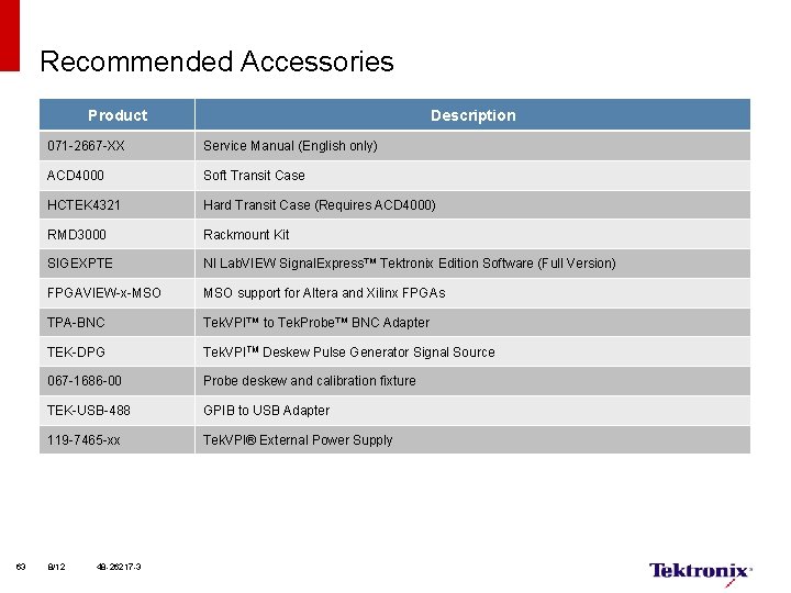
Recommended Accessories Product 63 Description 071 -2667 -XX Service Manual (English only) ACD 4000 Soft Transit Case HCTEK 4321 Hard Transit Case (Requires ACD 4000) RMD 3000 Rackmount Kit SIGEXPTE NI Lab. VIEW Signal. Express™ Tektronix Edition Software (Full Version) FPGAVIEW-x-MSO support for Altera and Xilinx FPGAs TPA-BNC Tek. VPI™ to Tek. Probe™ BNC Adapter TEK-DPG Tek. VPITM Deskew Pulse Generator Signal Source 067 -1686 -00 Probe deskew and calibration fixture TEK-USB-488 GPIB to USB Adapter 119 -7465 -xx Tek. VPI® External Power Supply 8/12 48 -26217 -3
MSO/DPO 2000 B Series Ordering Information 64
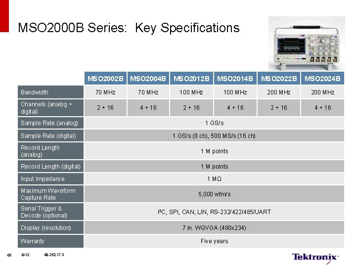
MSO 2000 B Series: Key Specifications MSO 2002 B MSO 2004 B Bandwidth Channels (analog + digital) MSO 2014 B MSO 2022 B MSO 2024 B 70 MHz 100 MHz 200 MHz 2 + 16 4 + 16 Sample Rate (analog) 1 GS/s Sample Rate (digital) 1 GS/s (8 ch), 500 MS/s (16 ch) Record Length (analog) 1 M points Record Length (digital) 1 M points Input Impedance Maximum Waveform Capture Rate Serial Trigger & Decode (optional) Display (resolution) Warranty 65 MSO 2012 B 8/12 48 -26217 -3 1 MΩ 5, 000 wfm/s I 2 C, SPI, CAN, LIN, RS-232/422/485/UART 7 in. WQVGA (480 x 234) Five years
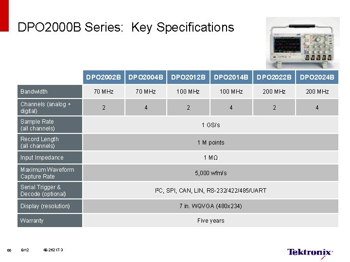
DPO 2000 B Series: Key Specifications Bandwidth Channels (analog + digital) Sample Rate (all channels) Record Length (all channels) Input Impedance Maximum Waveform Capture Rate Serial Trigger & Decode (optional) Display (resolution) Warranty 66 8/12 48 -26217 -3 DPO 2002 B DPO 2004 B DPO 2012 B DPO 2014 B DPO 2022 B DPO 2024 B 70 MHz 100 MHz 200 MHz 2 4 2 4 1 GS/s 1 M points 1 MΩ 5, 000 wfm/s I 2 C, SPI, CAN, LIN, RS-232/422/485/UART 7 in. WQVGA (480 x 234) Five years
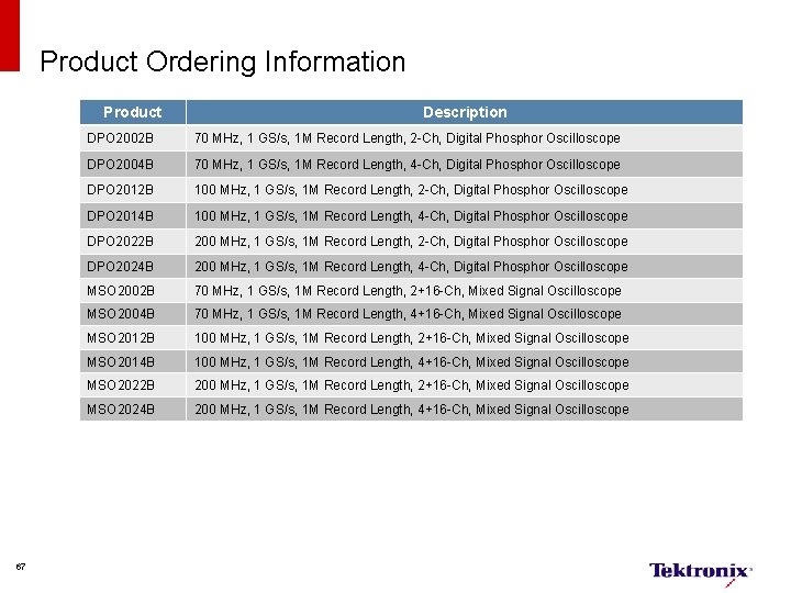
Product Ordering Information Product 67 Description DPO 2002 B 70 MHz, 1 GS/s, 1 M Record Length, 2 -Ch, Digital Phosphor Oscilloscope DPO 2004 B 70 MHz, 1 GS/s, 1 M Record Length, 4 -Ch, Digital Phosphor Oscilloscope DPO 2012 B 100 MHz, 1 GS/s, 1 M Record Length, 2 -Ch, Digital Phosphor Oscilloscope DPO 2014 B 100 MHz, 1 GS/s, 1 M Record Length, 4 -Ch, Digital Phosphor Oscilloscope DPO 2022 B 200 MHz, 1 GS/s, 1 M Record Length, 2 -Ch, Digital Phosphor Oscilloscope DPO 2024 B 200 MHz, 1 GS/s, 1 M Record Length, 4 -Ch, Digital Phosphor Oscilloscope MSO 2002 B 70 MHz, 1 GS/s, 1 M Record Length, 2+16 -Ch, Mixed Signal Oscilloscope MSO 2004 B 70 MHz, 1 GS/s, 1 M Record Length, 4+16 -Ch, Mixed Signal Oscilloscope MSO 2012 B 100 MHz, 1 GS/s, 1 M Record Length, 2+16 -Ch, Mixed Signal Oscilloscope MSO 2014 B 100 MHz, 1 GS/s, 1 M Record Length, 4+16 -Ch, Mixed Signal Oscilloscope MSO 2022 B 200 MHz, 1 GS/s, 1 M Record Length, 2+16 -Ch, Mixed Signal Oscilloscope MSO 2024 B 200 MHz, 1 GS/s, 1 M Record Length, 4+16 -Ch, Mixed Signal Oscilloscope
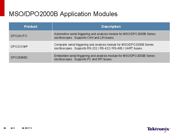
MSO/DPO 2000 B Application Modules Product 68 Description DPO 2 AUTO Automotive serial triggering and analysis module for MSO/DPO 2000 B Series oscilloscopes. Supports CAN and LIN buses. DPO 2 COMP Computer serial triggering and analysis module for MSO/DPO 2000 B Series oscilloscopes. Supports RS-232 / RS-422 / RS-485 / UART buses. DPO 2 EMBD Embedded serial triggering and analysis module for MSO/DPO 2000 B Series oscilloscopes. Supports I 2 C and SPI buses. 8/12 48 -26217 -3
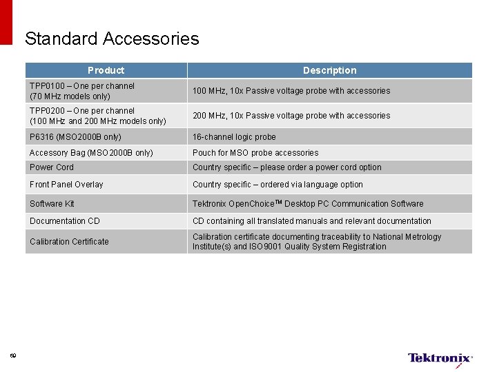
Standard Accessories Product 69 Description TPP 0100 – One per channel (70 MHz models only) 100 MHz, 10 x Passive voltage probe with accessories TPP 0200 – One per channel (100 MHz and 200 MHz models only) 200 MHz, 10 x Passive voltage probe with accessories P 6316 (MSO 2000 B only) 16 -channel logic probe Accessory Bag (MSO 2000 B only) Pouch for MSO probe accessories Power Cord Country specific – please order a power cord option Front Panel Overlay Country specific – ordered via language option Software Kit Tektronix Open. Choice. TM Desktop PC Communication Software Documentation CD CD containing all translated manuals and relevant documentation Calibration Certificate Calibration certificate documenting traceability to National Metrology Institute(s) and ISO 9001 Quality System Registration
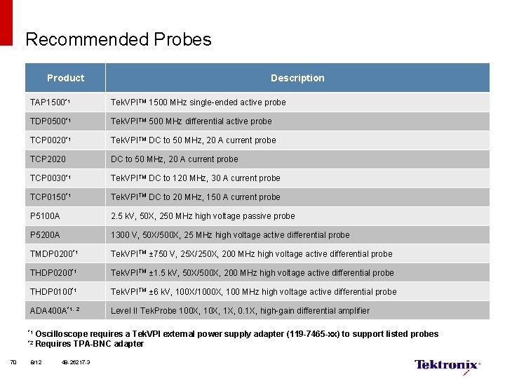
Recommended Probes Product TAP 1500*1 Tek. VPITM 1500 MHz single-ended active probe TDP 0500*1 Tek. VPITM 500 MHz differential active probe TCP 0020*1 Tek. VPITM DC to 50 MHz, 20 A current probe TCP 2020 DC to 50 MHz, 20 A current probe TCP 0030*1 Tek. VPITM DC to 120 MHz, 30 A current probe TCP 0150*1 Tek. VPITM DC to 20 MHz, 150 A current probe P 5100 A 2. 5 k. V, 50 X, 250 MHz high voltage passive probe P 5200 A 1300 V, 50 X/500 X, 25 MHz high voltage active differential probe TMDP 0200*1 Tek. VPITM ± 750 V, 25 X/250 X, 200 MHz high voltage active differential probe THDP 0200*1 Tek. VPITM ± 1. 5 k. V, 50 X/500 X, 200 MHz high voltage active differential probe THDP 0100*1 Tek. VPITM ± 6 k. V, 100 X/1000 X, 100 MHz high voltage active differential probe ADA 400 A*1, 2 Level II Tek. Probe 100 X, 1 X, 0. 1 X, high-gain differential amplifier *1 *2 70 Description Oscilloscope requires a Tek. VPI external power supply adapter (119 -7465 -xx) to support listed probes Requires TPA-BNC adapter 8/12 48 -26217 -3
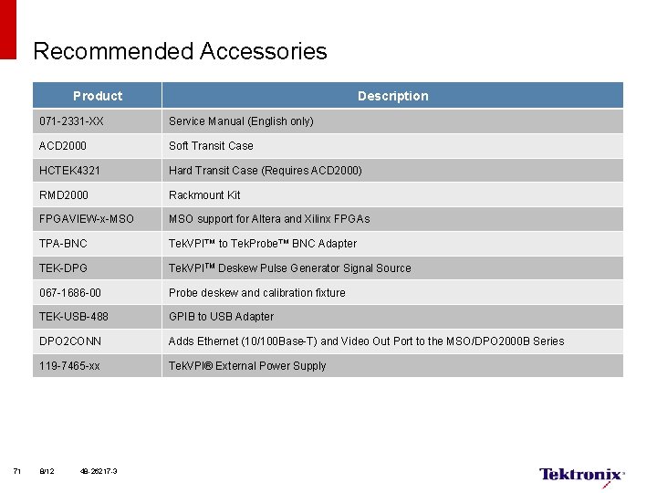
Recommended Accessories Product 71 Description 071 -2331 -XX Service Manual (English only) ACD 2000 Soft Transit Case HCTEK 4321 Hard Transit Case (Requires ACD 2000) RMD 2000 Rackmount Kit FPGAVIEW-x-MSO support for Altera and Xilinx FPGAs TPA-BNC Tek. VPI™ to Tek. Probe™ BNC Adapter TEK-DPG Tek. VPITM Deskew Pulse Generator Signal Source 067 -1686 -00 Probe deskew and calibration fixture TEK-USB-488 GPIB to USB Adapter DPO 2 CONN Adds Ethernet (10/100 Base-T) and Video Out Port to the MSO/DPO 2000 B Series 119 -7465 -xx Tek. VPI® External Power Supply 8/12 48 -26217 -3
Thank You 72
- Slides: 72