MSeal SK Corporation 2 Seal 4 Seal Hydraulic
 SK Corporation")


 Hydraulic Force의 이해 A B G P = =")
 Opening Force ① Hydraulic Force Seal face 사이에는 Liquid Film나 Vapor나 하나도 없거나")
 Closing Force와 Opening Force의 관계 ① Closing Force가 더 큰 경우 2개의 Closing")


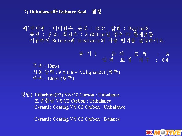
 Unbalance와 Balance Seal 결정")
 Unbalance와 Balance Seal 결정")


")
. 주로 tandem seal의 buffer fluid에 사용하는")
 돌아가기")
 돌아가기")
 돌아가기")
 돌아가기")
 돌아가기")

 돌아가기")
 돌아가기")
 돌아가기")
 돌아가기")
 돌아가기")


 Multi spring")
 Water service 2) Service with")
 Lethal, toxic substances 2) hydrocarbon pumps operating @ temperature")

 Single seal : 180 C 미만 : use plan")
 Special considerations (1) Quenching : Normally to avoid coking and crystallization at seal")


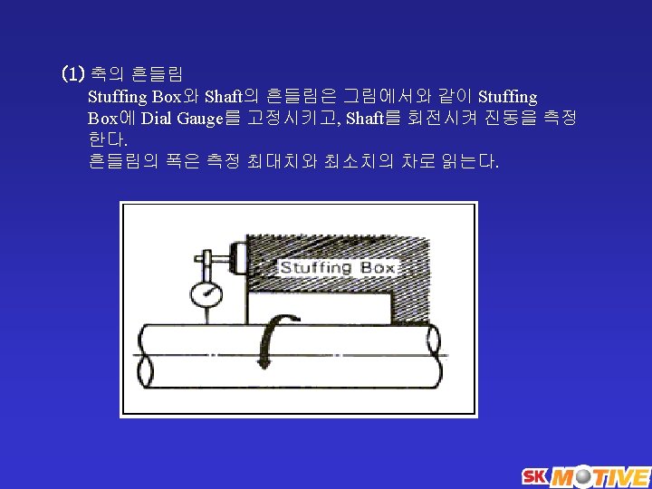
 Shaft와 Stuffing Box의 동심도 (3) Shaft와 Stuffing Box의 직각도")
- Slides: 86
축봉장치(M/Seal) SK Corporation
2. Seal 선정
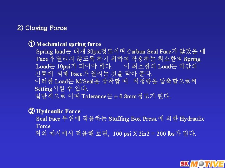
4. Seal Hydraulic Balance 1) Hydraulic Force의 이해 A B G P = = Spring Loaded Face (Area : 2 in 2) Stationary Face (Area : 2 in 2) Gland Hydraulic Press. (100 psi) 일 경우, Hydraulic Force 는 Press (lbs. /in 2) X Area(in 2) = Force (lbs. )
3) Opening Force ① Hydraulic Force Seal face 사이에는 Liquid Film나 Vapor나 하나도 없거나 Liquid Film과 Vapor의 혼합 형태로 있게 된다. 이때 Stationary B는 Gland G에 의해 움직일 수 없으므로, Spring Load가 작용하는 Face A에 Hydraulic force가 작용한다. Seal Face를 가로 질러 Press. Drop이 일직선 또는 Linear하다고 가정하면 다음과 같은 Average 값을 갖는다. 50 lbs/in 2 X 2 in 2 = 100 lbs
4) Closing Force와 Opening Force의 관계 ① Closing Force가 더 큰 경우 2개의 Closing Force와 3개의 Opening Force중 Closing Force가 더 크면 Seal온도가 상승하여 손상되거나 Pump 효율이 떨어지고 Energy가 소비된다. ② Opening Force가 더 큰 경우 이 경우는 Seal이 Leaking된다. ③ Seal Balance Opening 과 Closing Force가 균형을 이루어 온도가 올라 가거나 Leak되지 않는다. 대개 Hydraulic Closing Force는 Opening Force의 2배이므로, Closing Area를 줄이기 위하여 Seal 안쪽에 Sleeve를 설치하여 Closing Force를 감소시킨다.
여기서 Closing Force는 100 lbs/in 2 X 1 in 2 = 100 lbs Opening Force는 50 lbs/in 2 X 2 in 2 = 100 lbs 위에서 살펴 보았듯이 Hydraulic Force는 Seal 표면에서 Closing Force와 Opening Force가 서로 상쇄된다. 따라서, Closing Force중 Spring Force와 Seal Face를 Open하려는 Hydrodynamic Force와 원심력이 남게 된다. 즉, (1) Seal Face에서 Non-Linear한 Press. Drop. (2) Hydrodynamic Opening Force (3) 원심력 이를 해결하기 위하여 Hydraulic Force의 Overbalancing을 하게 되었다.
50%의 Seal Face Area대신에 70%의 Seal Face Area는 Hydraulic Closing Force를 보다 더 커지게 한다. 이러한 70 -30 Balance는 대개 Seal Vendor에서 사용하는 Standard다. Seal 의 Designer는 이러한 Sleeve Over Balance의 Percentage를 바꿈으로써 조절할 수 있다.
7) Unbalance와 Balance Seal 결정
7) Unbalance와 Balance Seal 결정
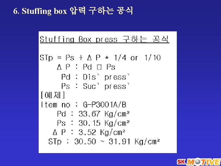
• Seal Chamber Press. Single stage suction overhung type ☞ P = s. P + 0. 15(d. P - s. P) 예) Suc’ press. 10 psi Disch’ press. 200 psi Seal chamber ? ☞ P = 10 + 0. 15(200 -10) * Balance hole이 없는 경우 : P = d. P
• Seal Chamber Press. Vane type ☞ P = s. P + C (d. P - s. P) Single stage double suction type ☞ P = s. P Multi stage type ☞ P = s. P
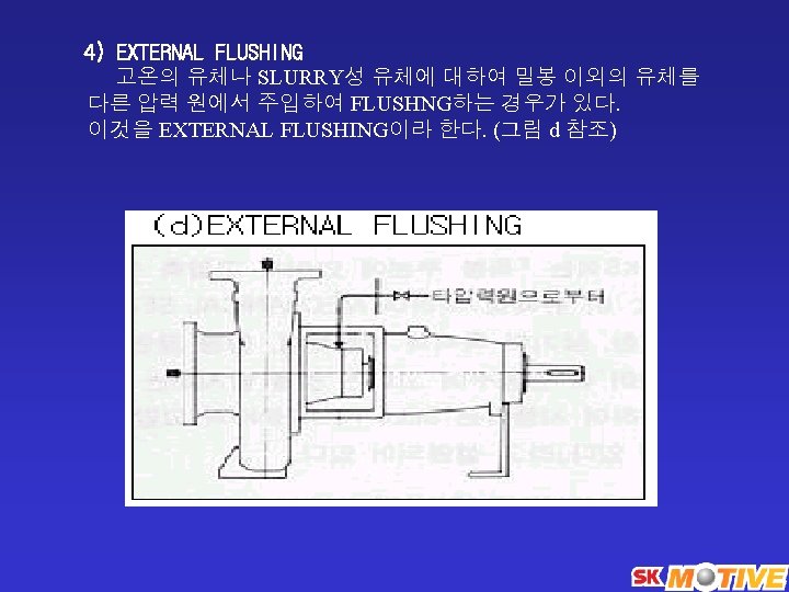
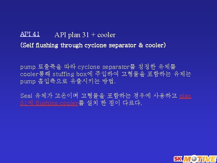
API 21 -23 은 cooler 가 있음 API 21 (Self flushing through heat exchanger) Pump 토출측을 따라 orifice와 cooler를 통해 stuffing box에 주입하 는 배관 방법. Seal 유체가 고온의 경우 seal면의 윤활 및 packing, gasket 의 보호를 목적으로 flushing 액을 냉각할 목적으로 plan 11에 flushing cooler를 설치한다. 180 ℃ 이상에서 사용 API 22 (Self flushing through heat exchanger & strainer) pump 토출측을 따라 orifice와 cooler, strainer 를 통해 stuffing box 에 주입하는 배관 방법. 필요에 따라서는 온도계를 설치한다. Seal 유체 가 고온이며 고형물을 포함하는 경우에 사용한다. Plan 12에 flushing cooler를 설치한 것이다. API 610 8 th edition에는 없다
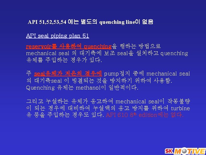
API 52 tandem seal (외부 압력 source가 없음). 주로 tandem seal의 buffer fluid에 사용하는 방법임. Buffer fluid는 mechanical seal에 설치된 internal pumping ring에 의해 순환 시킨다. Seal 유체가 대 기로 유출될 때 위험성이 있는 유체일 경우 사용하며 reservoir내의 압력상승과 buffer fluid의 액면을 관리하여 내측 및 대기측의 seal을 따라 누설되는 것을 감지할 수 있다. Reservoir에 압력 없음. API 53 double seal (외부에서 reservoir에 압력을 가함) Pressurized external barrier fluid reservoir. Internal pumping ring으로 순환 reservoir 압력 > 밀봉되는 process pressure API 54 외부압력 source는 있으나 reservoir가 없음 Pressurized external barrier fluid reservoir. External pressure system or pump로 순환
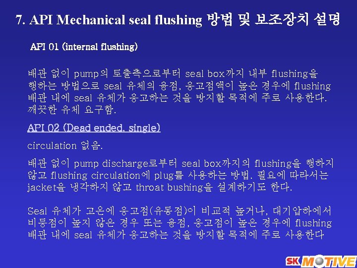
8. Mechanical seal piping plan API 01 (internal flushing) 돌아가기
seal piping plan API 02 (Dead ended, single) 돌아가기
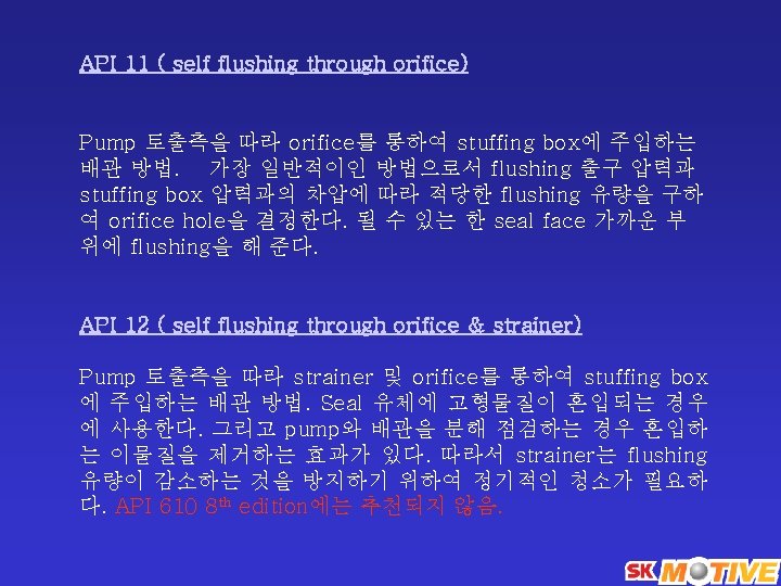
seal piping plan API 11 ( self flushing through orifice) 돌아가기
seal piping plan API 12 ( self flushing through orifice & strainer) 돌아가기
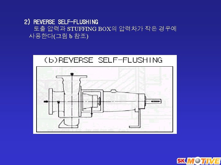
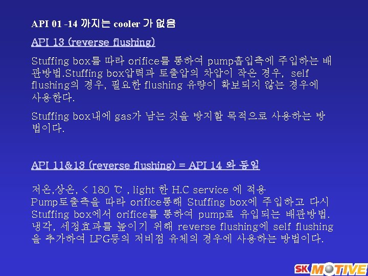
seal piping plan API 13 (reverse flushing) 돌아가기
seal piping plan API 01 -14 까지는 cooler 가 없음 API 14 (API 11 + 13) 돌아가기
seal piping plan API 21 (Self flushing through heat exchanger) 돌아가기
seal piping plan API 22 (Self flushing through heat exchanger & strainer) 돌아가기
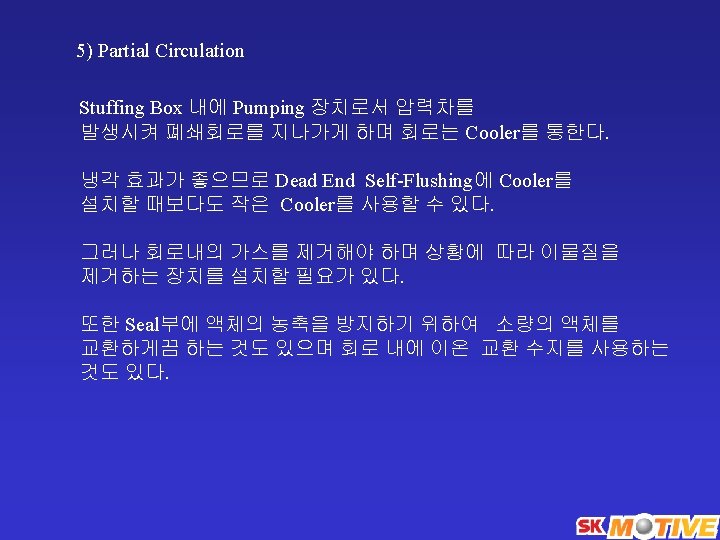
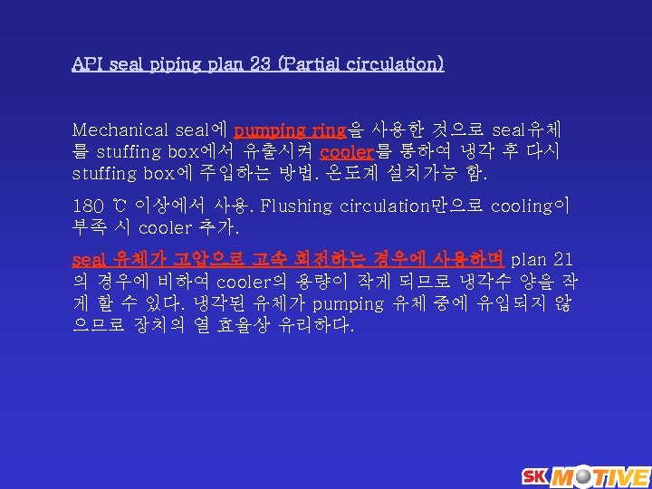
seal piping plan API seal piping plan 23 (Partial circulation) 돌아가기
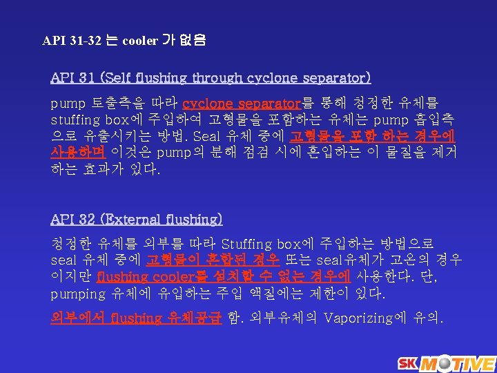
seal piping plan API 31 (Self flushing through cyclone separator) 돌아가기
seal piping plan API 32 (External flushing) 돌아가기
seal piping plan API plan 31 + cooler API 41 돌아가기
seal piping plan API seal piping plan 51 돌아가기
seal piping plan API 52 돌아가기
seal piping plan API 53 돌아가기
seal piping plan API 54 돌아가기
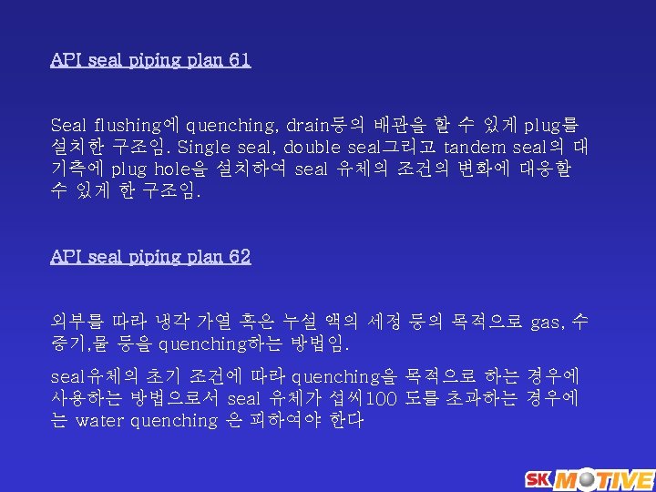
seal piping plan API seal piping plan 61 돌아가기
seal piping plan API seal piping plan 62 돌아가기
9. Seal material and classification code BSTFM Balanced / Single throttle bushing / FKM gasket / Carbon-Tungsten carbide sealing ring First letter : Balanced(B) or Unbalanced (U) Second letter : Single(S), Unpressurized dual(T) Third letter : Seal gland type (P=plain, no throttle bushing; T = throttle bushing) Fourth letter : Gasket materials Fifth letter : Face materials(see Table H-5)
재질사항 Single spring seal의 spring 재질: Austenite 계열(sus 316 or eq. ) Multi spring seal의 spring 재질: Hastelloy C Metal bellows 부식 율 < 50 micrometer (2 mils) / 년
10. Mechanical seal plan 적용기준 사례소개 Single seals 1) Water service 2) Service with less than 10% volatile organic compound* (defined below) * Volatile organic compound is defined as any volatile compound containing carbon, excluding CH 4, CO 2, metallic carbides & carbonates, carbonic acid, ammonium carbonate, fluorocarbon compounds.
Tandem or Double seals 1) Lethal, toxic substances 2) hydrocarbon pumps operating @ temperature above autoignition temperature 3) Liquids where the weight percent evaporated is more than 10% at 150 C 4) C 4 or lighter hydrocarbon or vapor pressure is more than 2. 8 kg/cm 2 a @ 38 C 5) Use plan 53 for corrosive liquid requiring secondary seal 6) Use plan 53 if the stuffing box pressure is less than 1. 8 kg/cm 2 above the vapor pressure and the discharge pressure is insufficitent to pressurize the chanber(by plan 11) to obtain this margin to avoid flashing
Seal type Pusher type below 180 C rated temperature Bellow seal above 180 C rated temperature
Seal flush plans 적용기준 1) Single seal : 180 C 미만 : use plan 11 180 C 이상 : use plan 21 or plan 23 (uop uses plan 23) Exceptions : - water pump : use plan 23 above 85 C - Hi-temp bellow seal : use plan 11 2) Tandem seal : 180 C 미만 : use plan 11/52 180 C 이상 : use plan 21/52 or 23/52 Exceptions : - Hi-temp bellow use seal plan 11/52
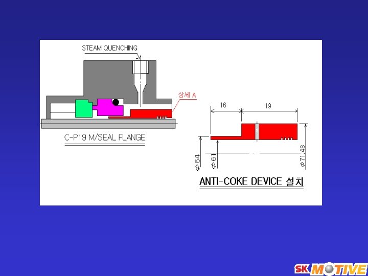
3) Special considerations (1) Quenching : Normally to avoid coking and crystallization at seal face (2) Dirty services : replace plans 11, 21 and 23 in all arrangement above with plans 31, 32 or 41 depending on the particle nature and size.
Standard plan 52/53 1. Piping shall be all 316 ss or 304 ss material. 2. Seal pot shall be of material equal or better than the pump casing. 3. Specify cooling as standard. 4. See attached sketches SK-A and SK-B 5. Except for water piping socket welded flanges shall be used 6. Min reservoir capacity 15 liters 7. Vendor to specify all liquid levels 8. Vendor to supply all components shown
SK-A
SK-B
(2) Shaft와 Stuffing Box의 동심도 (3) Shaft와 Stuffing Box의 직각도