MSD Project Team P 08454 Underwater Thruster Design


- Slides: 15
MSD Project Team P 08454 Underwater Thruster Design Anthony Squaire – Team Leader - Industrial and Systems Engineering Alan Mattice – Lead Engineer - Mechanical Engineer Cody Ture - Mechanical Engineer Brian Bullen – Mechanical Engineer Charles Trumble – Mechanical Engineer Aron Khan – Electrical Engineer Jeff Cowan – Electrical Engineer Andre Mc. Rucker – Computer Engineer
Project Background • Derived from one of the most successful projects in RIT’s history: P 06606 • Project mission is to design an open source thruster that can be used and/or improved for future RIT MSD projects • Customers: • Dresser Rand • Dr. Hensel and the RIT Mechanical Engineering Department • Hydroacoustics • The design needs to be competitive with the current thruster designs in use: • Seabotix • Tecnadyne Figure 1: ROV Design from MSD project P 06606
High Level Customer Needs • Thrust must be improved over the current Seabotix Thruster • Power consumption must be better than the Tecnadyne Thruster • Mounts as easy as the Tecnadyne Thruster • Operational in 400 ft. (173 psi) of water • Needs to work in temperatures from 38 -75 F • Modular, open source design • Comply with federal, state, and local laws, including the policies and procedures of RIT
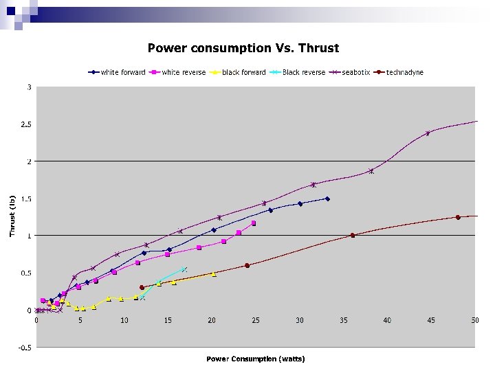
Current State of Design • Completed three design reviews and met with the customers so that they could voice any lingering concerns • Motor Supplier failed to meet supply demand for project • Assembled two prototype thrusters • Tested for verification (results given in Design Specs slide) • Technical Paper and Project Poster complete • EDGE layout planned and ready to be updated with all current documentation
System Architecture
Assembly Drawing Figure 3: Front View of thruster Figure 2: Rear View of thruster Figure 4: Section view of P 08454 thruster design (Note: Does not include rear section that will house the electronics)
Exploded Assembly Animation
Rice Nozzle Figure 6: Outer and inner flow of the Kort and Rice designs Rice Nozzle – Designed to increase thrust efficiency and reduce drag In above figure: • Reduced drag • Increased thrust
Nozzle / Impeller Nozzle Attachment • Use specialty designed part called ducting brace. • Impeller is placed in position to maximize the geometrical effects of the nozzle (the slope transition) Figure 5: Impeller from Silverstone Final Selection • When compared to black impeller, far more thrust • Impeller from Silverstone is better choice because it is more aggressive and efficient when compared to black impeller
Motor Comparison
Testing Figure 7: Test Rig
Comparing to Current Designs Figure 9: P 08454’s Thruster Figure 8: Seabotix Thruster Figure 10: Tecnadyne Thruster Cost (Dollars) Thrust (lbf) Power Consumptio n (watts) 600. 00 1. 5 (Forward), 1. 2 (Reverse) 33. 12 Yes Seabotix 1, 000. 00 4. 8 (Forward), 4. 4 (Reverse) 80 No No Tecnadyne 4, 000. 00 12 (Forward), 4 (Reverse) 50. 4 No Yes P 08454's Design Open Source Design Feedback from the Motor * Numbers not yet known but design intends to be comparable to both thrusters using different impeller designs • Listed above are the most important metrics when comparing the three thruster designs.
Future of Design • Place thrusters on Hydroacoustics ROV for testing and verify on ROV performance • Minimize thrust to weight and thrust to power ratios • Build RIT ROV and integrate P 08454’s and P 08456’s designs into vehicle • Look at possible uses for software and electrical control for a land based vehicle • Possibly look at Land/Sea hybrid Figure 12: Current Hydroacoustics ROV vehicle
Figure Sources n n n n Figure 1: Concept Model of P 06606’s ROV: https: //edge. rit. edu/content/P 08454/public/Home Figure 5: Silverstone Tek: http: //www. silverstonetek. com Figure 6: Propeller Pages: http: //www. propellerpages. com/? c=nozzles&f=How_Nozzles_Work Figure 8: Seabotix: http: //www. seabotix. com/products/btd 150. htm Figure 10: Tecnadyne: http: //www. tecnadyne. com/images/Model-260 -2. jpg Figure 11: P 06606: http: //designserver. rit. edu/Archives/P 06606/webcontent/Images/large_photos/Sponsor. ROV 2. jpg Figure 12: Hydroacoustics: http: //hydroacousticsinc. com/marine_technology. php Information Sources n n n n Anaheim Automation: http: //www. anaheimautomation. com Seabotix Inc. : http: //www. seabotix. com/products/btd 150. htm Tecnadyne: http: //www. tecnadyne. com/Brochure/Model%20260%20 Brochure. pdf Huco Dynatork: http: //www. huco. com ST Microelectronics: http: //www. st. com Microchip: http: //www. microchip. com Atmel Corporation: http: //www. atmel. com Mc. Master-Carr: http: //www. mcmaster. com/