
MQXF coil crosssection status Paolo Ferracin Hi Lumi
- Slides: 20
MQXF coil cross-section status Paolo Ferracin Hi. Lumi WP 3 Video-meeting 28 August, 2012
Outline • Update of MQXF coil cross-section with cable growth during reaction (from v 2 to v 3) • Length of coil ends Paolo Ferracin 28/08/2012 2
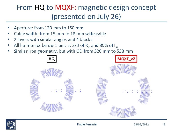
From HQ to MQXF: magnetic design concept (presented on July 26) • • • Aperture: from 120 mm to 150 mm Cable width: from 15 mm to 18 mm wide cable 2 layers with similar angles and 4 blocks All harmonics below 1 unit at 2/3 of Rin and 80% of Iss Similar iron geometry, but with OD from 520 mm to 558 mm HQ MQXF_v 2 Paolo Ferracin 28/08/2012 3
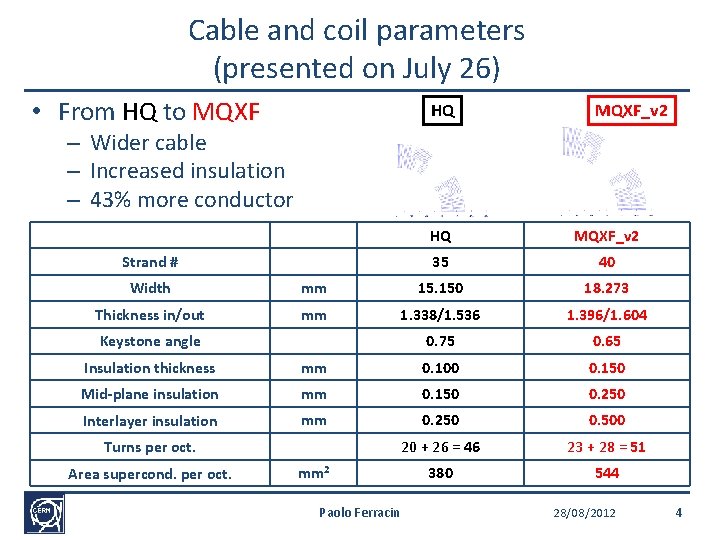
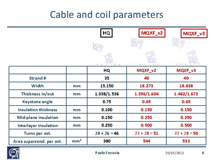
Cable and coil parameters (presented on July 26) • From HQ to MQXF HQ MQXF_v 2 – Wider cable – Increased insulation – 43% more conductor Units Strand # HQ MQXF_v 2 35 40 Width mm 15. 150 18. 273 Thickness in/out mm 1. 338/1. 536 1. 396/1. 604 0. 75 0. 65 Keystone angle Insulation thickness mm 0. 100 0. 150 Mid-plane insulation mm 0. 150 0. 250 Interlayer insulation mm 0. 250 0. 500 20 + 26 = 46 23 + 28 = 51 380 544 Turns per oct. Area supercond. per oct. mm 2 Paolo Ferracin 28/08/2012 4
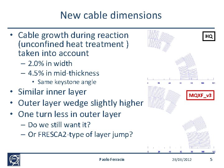
New cable dimensions • Cable growth during reaction (unconfined heat treatment ) taken into account HQ – 2. 0% in width – 4. 5% in mid-thickness • Same keystone angle • Similar inner layer • Outer layer wedge slightly higher • One turn less in outer layer MQXF_v 3 – Do we still want it? – Or FRESCA 2 -type of layer jump? Paolo Ferracin 28/08/2012 5
Cable and coil parameters HQ Units Strand # MQXF_v 2 MQXF_v 3 HQ MQXF_v 2 MQXF_v 3 35 40 40 Width mm 15. 150 18. 273 18. 638 Thickness in/out mm 1. 338/1. 536 1. 396/1. 604 1. 462/1. 673 0. 75 0. 65 Keystone angle Insulation thickness mm 0. 100 0. 150 Mid-plane insulation mm 0. 150 0. 250 Interlayer insulation mm 0. 250 0. 500 20 + 26 = 46 23 + 28 = 51 22 + 28 = 50 380 544 533 Turns per oct. Area supercond. per oct. mm 2 Paolo Ferracin 28/08/2012 6
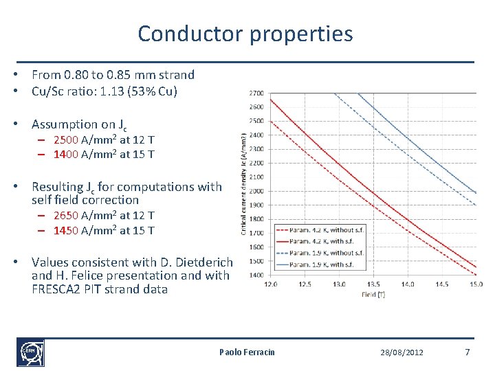
Conductor properties • From 0. 80 to 0. 85 mm strand • Cu/Sc ratio: 1. 13 (53% Cu) • Assumption on Jc – 2500 A/mm 2 at 12 T – 1400 A/mm 2 at 15 T • Resulting Jc for computations with self field correction – 2650 A/mm 2 at 12 T – 1450 A/mm 2 at 15 T • Values consistent with D. Dietderich and H. Felice presentation and with FRESCA 2 PIT strand data Paolo Ferracin 28/08/2012 7
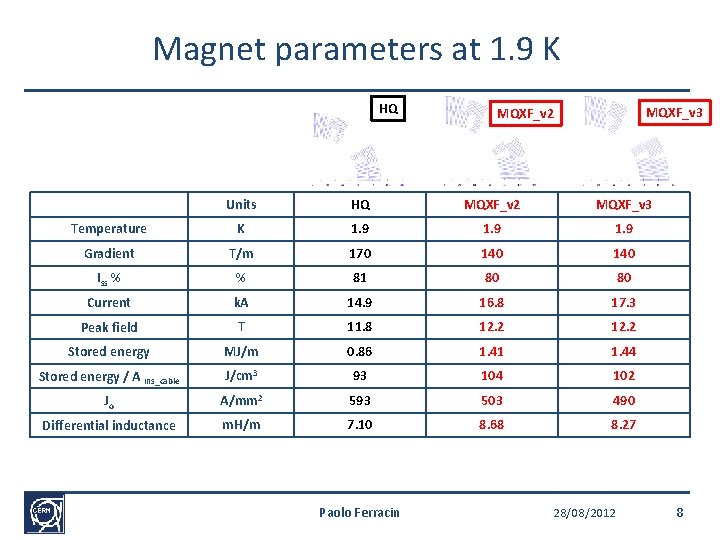
Magnet parameters at 1. 9 K HQ MQXF_v 3 MQXF_v 2 Units HQ MQXF_v 2 MQXF_v 3 Temperature K 1. 9 Gradient T/m 170 140 Iss % % 81 80 80 Current k. A 14. 9 16. 8 17. 3 Peak field T 11. 8 12. 2 Stored energy MJ/m 0. 86 1. 41 1. 44 Stored energy / A ins_cable J/cm 3 93 104 102 Jo A/mm 2 593 503 490 Differential inductance m. H/m 7. 10 8. 68 8. 27 Paolo Ferracin 28/08/2012 8
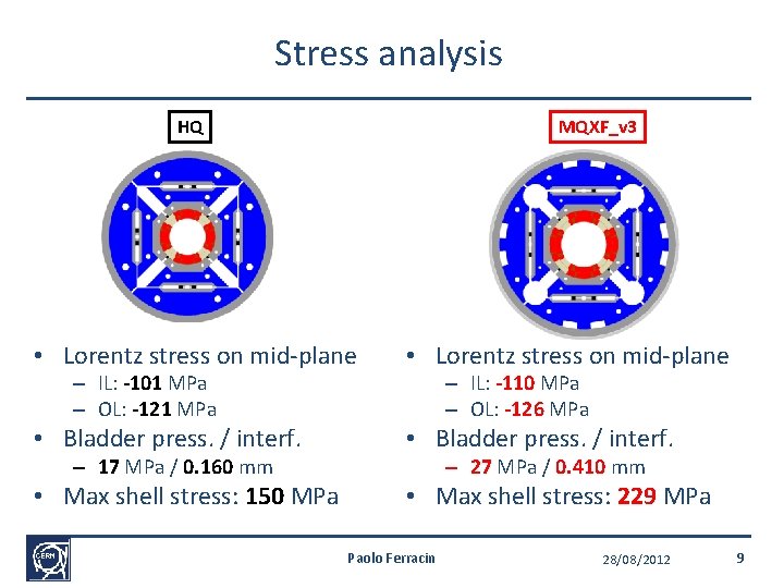
Stress analysis HQ MQXF_v 3 • Lorentz stress on mid-plane • Bladder press. / interf. • Max shell stress: 150 MPa • Max shell stress: 229 MPa – IL: -101 MPa – OL: -121 MPa – 17 MPa / 0. 160 mm – IL: -110 MPa – OL: -126 MPa – 27 MPa / 0. 410 mm Paolo Ferracin 28/08/2012 9
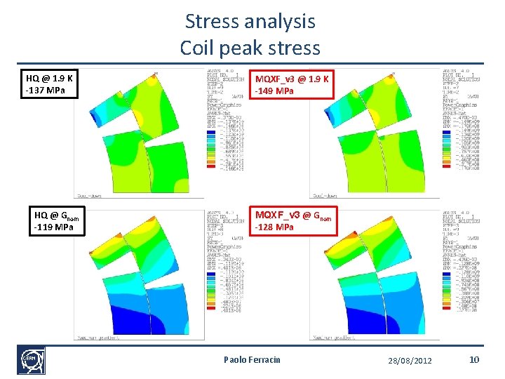
Stress analysis Coil peak stress HQ @ 1. 9 K -137 MPa HQ @ Gnom -119 MPa MQXF_v 3 @ 1. 9 K -149 MPa MQXF_v 3 @ Gnom -128 MPa Paolo Ferracin 28/08/2012 10
Outline • Update of MQXF coil cross-section with cable growth during reaction (from v 2 to v 3) • Length of coil ends Paolo Ferracin 28/08/2012 11
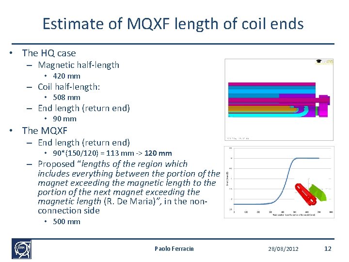
Estimate of MQXF length of coil ends • The HQ case – Magnetic half-length • 420 mm – Coil half-length: • 508 mm – End length (return end) • 90 mm • The MQXF – End length (return end) • 90*(150/120) = 113 mm -> 120 mm – Proposed “lengths of the region which includes everything between the portion of the magnet exceeding the magnetic length to the portion of the next magnet exceeding the magnetic length (R. De Maria)”, in the nonconnection side • 500 mm Paolo Ferracin 28/08/2012 12
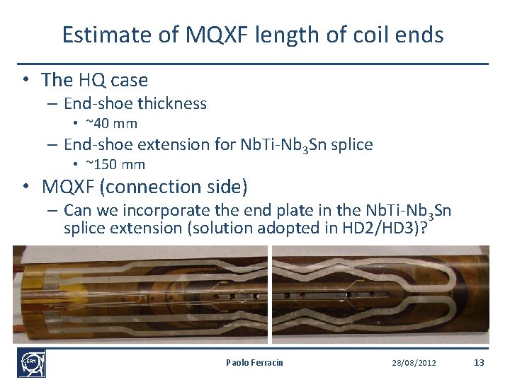
Estimate of MQXF length of coil ends • The HQ case – End-shoe thickness • ~40 mm – End-shoe extension for Nb. Ti-Nb 3 Sn splice • ~150 mm • MQXF (connection side) – Can we incorporate the end plate in the Nb. Ti-Nb 3 Sn splice extension (solution adopted in HD 2/HD 3)? Paolo Ferracin 28/08/2012 13
Appendix Paolo Ferracin 28/08/2012 14
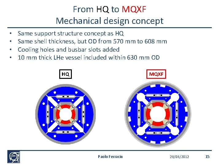
From HQ to MQXF Mechanical design concept • • Same support structure concept as HQ Same shell thickness, but OD from 570 mm to 608 mm Cooling holes and busbar slots added 10 mm thick LHe vessel included within 630 mm OD HQ MQXF Paolo Ferracin 28/08/2012 15
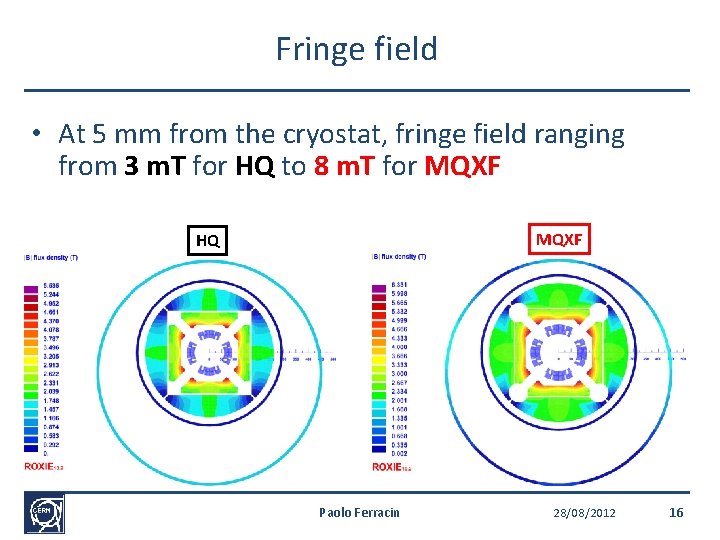
Fringe field • At 5 mm from the cryostat, fringe field ranging from 3 m. T for HQ to 8 m. T for MQXF HQ Paolo Ferracin 28/08/2012 16
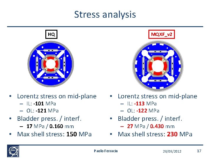
Stress analysis HQ MQXF_v 2 • Lorentz stress on mid-plane • Bladder press. / interf. • Max shell stress: 150 MPa • Max shell stress: 230 MPa – IL: -101 MPa – OL: -121 MPa – 17 MPa / 0. 160 mm – IL: -113 MPa – OL: -122 MPa – 27 MPa / 0. 430 mm Paolo Ferracin 28/08/2012 17
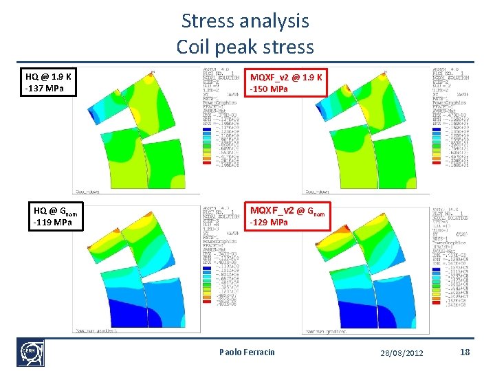
Stress analysis Coil peak stress HQ @ 1. 9 K -137 MPa HQ @ Gnom -119 MPa MQXF_v 2 @ 1. 9 K -150 MPa MQXF_v 2 @ Gnom -129 MPa Paolo Ferracin 28/08/2012 18
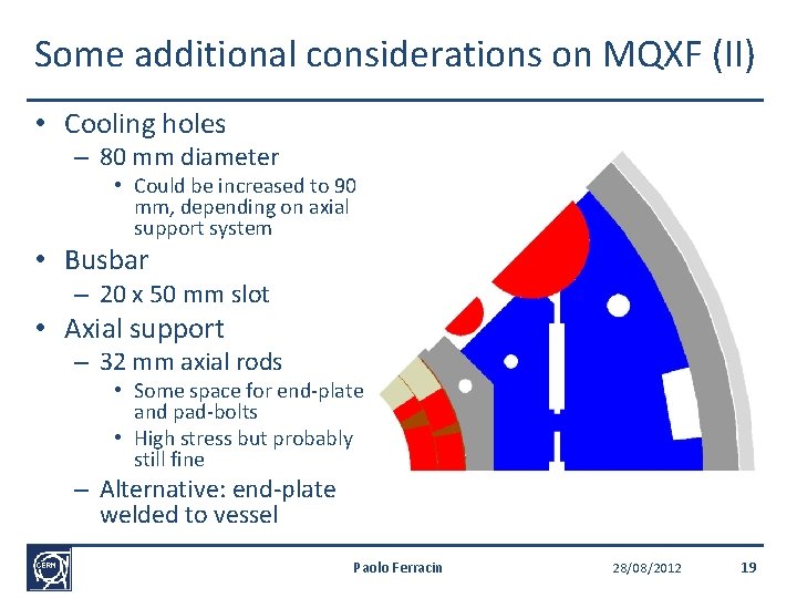
Some additional considerations on MQXF (II) • Cooling holes – 80 mm diameter • Could be increased to 90 mm, depending on axial support system • Busbar – 20 x 50 mm slot • Axial support – 32 mm axial rods • Some space for end-plate and pad-bolts • High stress but probably still fine – Alternative: end-plate welded to vessel Paolo Ferracin 28/08/2012 19
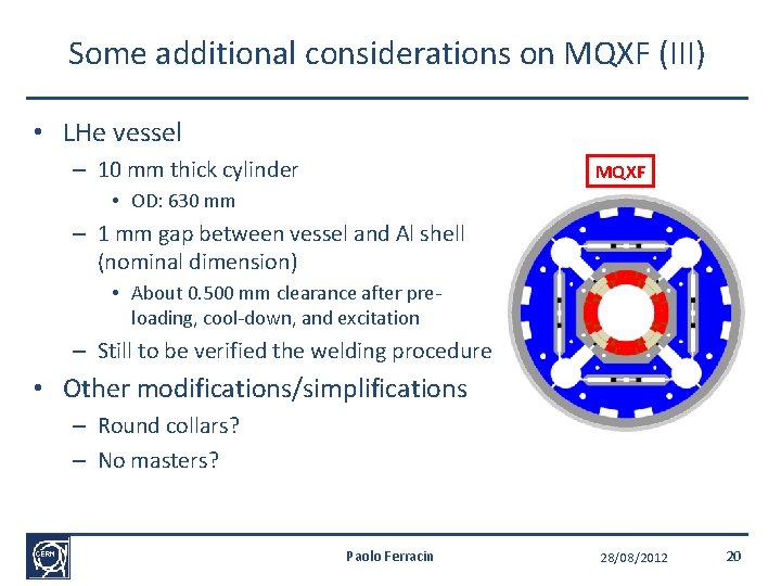
Some additional considerations on MQXF (III) • LHe vessel – 10 mm thick cylinder MQXF • OD: 630 mm – 1 mm gap between vessel and Al shell (nominal dimension) • About 0. 500 mm clearance after preloading, cool-down, and excitation – Still to be verified the welding procedure • Other modifications/simplifications – Round collars? – No masters? Paolo Ferracin 28/08/2012 20