
MPLS Technology fundamentals Sherif Toulan Technical Leader Cisco



- Slides: 31
MPLS Technology fundamentals Sherif Toulan Technical Leader, Cisco Systems Canada EDCS-1470619 Cisco Confidential 1
Sherif Toulan, Bio • Professional Engineers Ontario, P. Eng. # 90291410 • M. Eng. Degree in Electrical Engineering from University of Toronto, 1991 • Cisco Certified Internetwork Expert, CCIE# 4220, Routing & Switching • Project Management Professional, PMP# 511073 • 2000 – Present Employed by Cisco Systems Canada as Network Design Engineer, working with key Service Providers (Bell Canada, at&t, France Telecom to deploy MPLS technologies) • 1991 -2000 Employed by Bell Canada as Network Consulting Engineer designing networks for Service Providers & Enterprise Customers (Banks, Insurance companies, …etc. ) Cisco Systems 2 © 2016 Cisco Systems. All rights reserved.
Agenda “Topics” § MPLS Technology Basics § MPLS Traffic Engineering (TE) § MPLS Next Generation Technologies Session Summary Cisco Systems 3 © 2016 Cisco Systems. All rights reserved.
MPLS Technology Basics Cisco Confidential 4
Agenda § Evolution of MPLS § MPLS forwarding basics § MPLS forwarding example Summary Cisco Systems 5 © 2016 Cisco Systems. All rights reserved.
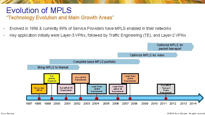
Evolution of MPLS “Technology Evolution and Main Growth Areas” • Evolved in 1996 & currently 99% of Service Providers have MPLS enabled in their networks • Key application initially were Layer-3 VPNs, followed by Traffic Engineering (TE), and Layer-2 VPNs Optimize MPLS for packet transport Optimize MPLS for video Complete base MPLS portfolio Bring MPLS to Market First L 3 VPNs Deployed Cisco ships MPLS 1997 1998 Cisco Systems Large Scale L 2 VPN Deployments First MPLS TE Deployments 1999 2000 2001 2002 Large Scale L 3 VPN Deployments 2003 2004 Large Scale MPLS TE Deployments 2005 2006 2007 2008 First MPLS Transport Profile Deployments 2009 2010 2011 2012 2013 2014 © 2016 Cisco Systems. All rights reserved.
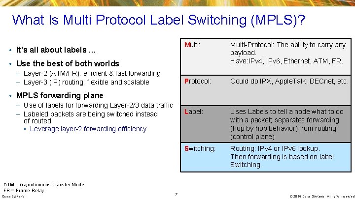
What Is Multi Protocol Label Switching (MPLS)? • It’s all about labels … Multi: Multi-Protocol: The ability to carry any payload. Have: IPv 4, IPv 6, Ethernet, ATM, FR. Protocol: Could do IPX, Apple. Talk, DECnet, etc. Label: Uses Labels to tell a node what to do with a packet; separates forwarding (hop by hop behavior) from routing (control plane) Switching: Routing: IPv 4 or IPv 6 lookup. Then forwarding is based on label Switching. • Use the best of both worlds – Layer-2 (ATM/FR): efficient & fast forwarding – Layer-3 (IP) routing: flexible and scalable • MPLS forwarding plane – Use of labels forwarding Layer-2/3 data traffic – Labeled packets are being switched instead of routed • Leverage layer-2 forwarding efficiency ATM = Asynchronous Transfer Mode FR = Frame Relay Cisco Systems 7 © 2016 Cisco Systems. All rights reserved.
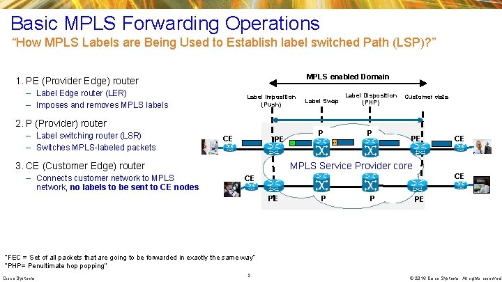
Basic MPLS Forwarding Operations “How MPLS Labels are Being Used to Establish label switched Path (LSP)? ” MPLS enabled Domain 1. PE (Provider Edge) router – Label Edge router (LER) – Imposes and removes MPLS labels Label Imposition (Push) Label Swap Label Disposition (PHP) P P Customer data 2. P (Provider) router – Label switching router (LSR) – Switches MPLS-labeled packets CE PE 3. CE (Customer Edge) router – Connects customer network to MPLS network, no labels to be sent to CE nodes L 2 L 1 PE CE MPLS Service Provider core CE CE PE P P PE “FEC = Set of all packets that are going to be forwarded in exactly the same way” “PHP= Penultimate hop popping” Cisco Systems 8 © 2016 Cisco Systems. All rights reserved.
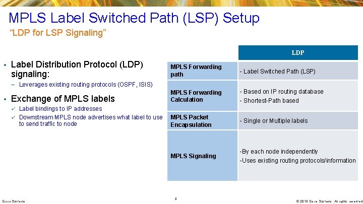
MPLS Label Switched Path (LSP) Setup “LDP for LSP Signaling” LDP • Label Distribution Protocol (LDP) signaling: MPLS Forwarding path - Label Switched Path (LSP) – Leverages existing routing protocols (OSPF, ISIS) • Exchange of MPLS labels MPLS Forwarding Calculation - Based on IP routing database - Shortest-Path based ü Label bindings to IP addresses ü Downstream MPLS node advertises what label to use to send traffic to node MPLS Packet Encapsulation MPLS Signaling Cisco Systems 9 - Single or Multiple labels -By each node independently -Uses existing routing protocols/information © 2016 Cisco Systems. All rights reserved.
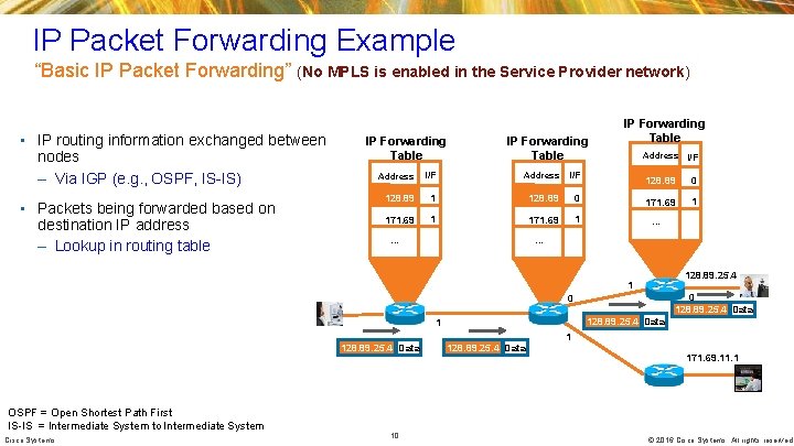
IP Packet Forwarding Example “Basic IP Packet Forwarding” (No MPLS is enabled in the Service Provider network) • IP routing information exchanged between nodes – Via IGP (e. g. , OSPF, IS-IS) • Packets being forwarded based on destination IP address – Lookup in routing table IP Forwarding Table Address I/F 128. 89 1 128. 89 0 171. 69 1 IP Forwarding Table Address I/F 128. 89 0 171. 69 1 … … … 128. 89. 25. 4 1 0 128. 89. 25. 4 Data 1 171. 69. 11. 1 OSPF = Open Shortest Path First IS-IS = Intermediate System to Intermediate System Cisco Systems 10 © 2016 Cisco Systems. All rights reserved.
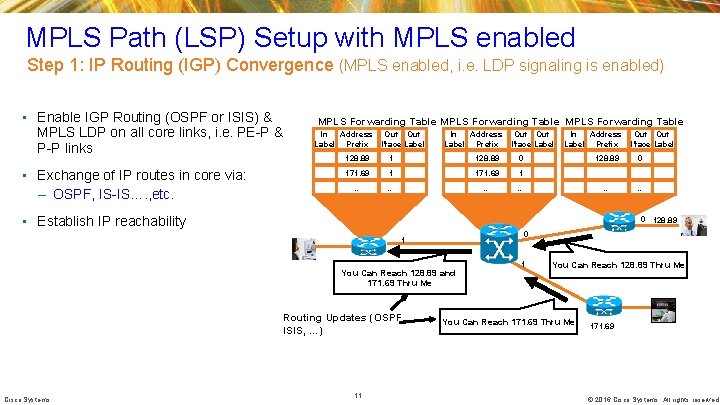
MPLS Path (LSP) Setup with MPLS enabled Step 1: IP Routing (IGP) Convergence (MPLS enabled, i. e. LDP signaling is enabled) • Enable IGP Routing (OSPF or ISIS) & MPLS LDP on all core links, i. e. PE-P & P-P links • Exchange of IP routes in core via: – OSPF, IS-IS…. , etc. MPLS Forwarding Table In Address Label Prefix Out Out I’face Label 128. 89 1 128. 89 0 171. 69 1 … … In Address Label Prefix 128. 89 0 … … • Establish IP reachability 0 128. 89 0 1 You Can Reach 128. 89 and 171. 69 Thru Me Routing Updates (OSPF, ISIS, …) Cisco Systems Out I’face Label 11 1 You Can Reach 128. 89 Thru Me You Can Reach 171. 69 Thru Me 171. 69 © 2016 Cisco Systems. All rights reserved.
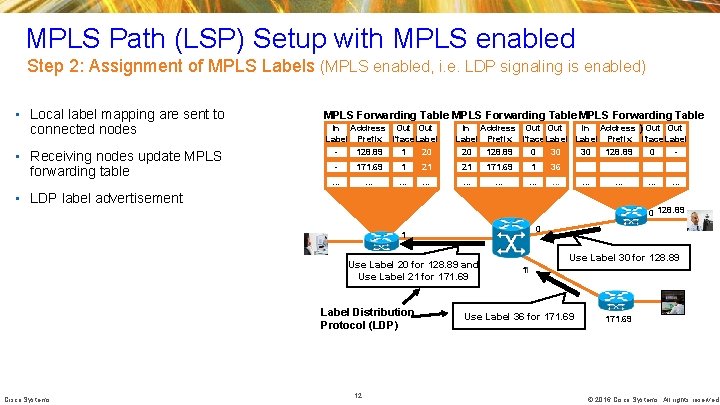
MPLS Path (LSP) Setup with MPLS enabled Step 2: Assignment of MPLS Labels (MPLS enabled, i. e. LDP signaling is enabled) • Local label mapping are sent to connected nodes • Receiving nodes update MPLS forwarding table MPLS Forwarding Table In Address Out Out In Address ) Out Label Prefix I’face. Label 128. 89 1 20 Label Prefix I’face. Label 20 128. 89 0 30 30 128. 89 0 - - 171. 69 1 21 21 171. 69 1 36 … … … … … • LDP label advertisement … 0 128. 89 0 1 Use Label 20 for 128. 89 and Use Label 21 for 171. 69 Label Distribution Protocol (LDP) Cisco Systems … 12 Use Label 30 for 128. 89 11 Use Label 36 for 171. 69 © 2016 Cisco Systems. All rights reserved.
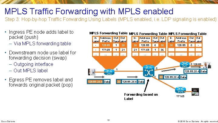
MPLS Traffic Forwarding with MPLS enabled Step 3: Hop-by-hop Traffic Forwarding Using Labels (MPLS enabled, i. e. LDP signaling is enabled) • Ingress PE node adds label to packet (push) – Via MPLS forwarding table • Downstream node use label forwarding decision (swap) – Outgoing interface – Out MPLS label • Egress PE removes label and forwards original packet (pop) MPLS Forwarding Table In Address Out Label Prefix I’face. Label 128. 89 1 20 In Address Out Out Label Prefix I’face. Label 20 128. 89 0 30 30 128. 89 0 - - 171. 69 1 21 21 171. 69 1 36 … … … 0 128. 89 0 1 128. 89. 25. 4 Data 13 30 128. 89. 25. 4 Data 20 128. 89. 25. 4 Data Forwarding based on Label Cisco Systems … 171. 69 © 2016 Cisco Systems. All rights reserved.
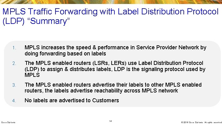
MPLS Traffic Forwarding with Label Distribution Protocol (LDP) “Summary” 1. MPLS increases the speed & performance in Service Provider Network by doing forwarding based on labels 2. The MPLS enabled routers (LSRs, LERs) use Label Distribution Protocol (LDP) to assign & distributes labels, LDP is the signaling protocol used by MPLS 3. The MPLS enabled routers advertise their labels to other MPLS enabled routers, the labels advertise reachability across MPLS network 4. No labels are advertised to Customers Cisco Systems 14 © 2016 Cisco Systems. All rights reserved.
MPLS Traffic Engineering Cisco Confidential 15
Agenda • MPLS Traffic Engineering (TE) motivation • MPLS TE Path Selection - Constraint-Based Shortest Path First (CSPF) • MPLS TE signaling – LSP Setup – Resource Reservation Protocol (RSVP) Summary Cisco Systems © 2016 Cisco Systems. All rights reserved.
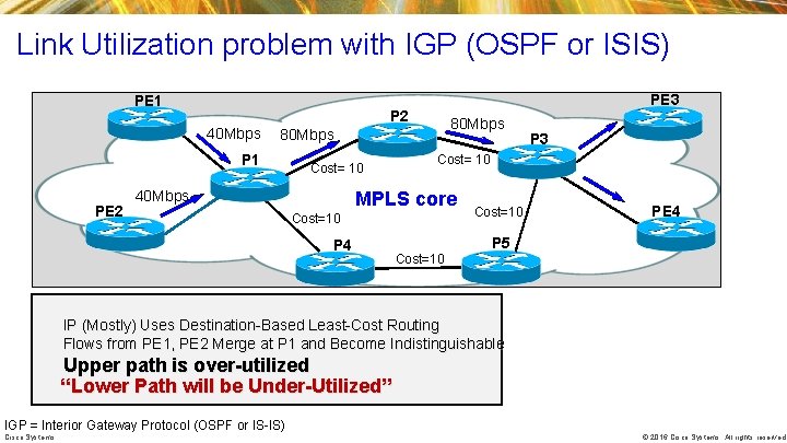
Link Utilization problem with IGP (OSPF or ISIS) PE 1 40 Mbps 80 Mbps P 1 PE 2 PE 3 P 2 Cost= 10 40 Mbps Cost= 10 MPLS core Cost=10 P 4 P 3 Cost=10 PE 4 P 5 Cost=10 IP (Mostly) Uses Destination-Based Least-Cost Routing Flows from PE 1, PE 2 Merge at P 1 and Become Indistinguishable Upper path is over-utilized “Lower Path will be Under-Utilized” IGP = Interior Gateway Protocol (OSPF or IS-IS) Cisco Systems © 2016 Cisco Systems. All rights reserved.
What MPLS-TE Technology solves? • MPLS TE solves link utilization problem, i. e. no oversubscription • P 1 is the HEADEND & sees all the links • P 1 computes paths on properties other than just least cost Next-Hop • Tunnel 1, Tunnel 2 are manually configured & path is explicitly enabled from P 1 to P 3 PE 3 Tunnel 1 • Tunnel 1 will take path P 1 -P 2 -P 3 PE 4 Tunnel 2 • Tunnel 2 will take different path P 1 -P 4 -P 5 -P 3 Node P 2 40 Mb P 1 Tunnel 2 Tunnel 2 P 4 Cisco Systems MPLS core PE 3 P 3 40 Mb PE 4 40 Mb P 5 © 2016 Cisco Systems. All rights reserved.
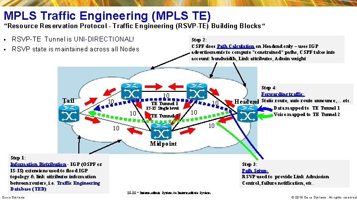
MPLS Traffic Engineering (MPLS TE) “Resource Reservation Protocol - Traffic Engineering (RSVP-TE) Building Blocks” RSVP-TE Tunnel is UNI-DIRECTIONAL! § RSVP state is maintained across all Nodes § Tail Step 2: CSPF does Path Calculation on Headend only – uses IGP advertisements to compute “constrained” paths, CSPF takes into account: bandwidth, Link attributes, Admin weight 10 10 10 TE Tunnel 1 10 IS-IS Single level TE Tunnel 2 10 Step 4: Forwarding traffic: Headend Static route, auto route announce, …. etc. Data mapped to TE Tunnel 1 Voice mapped to TE Tunnel 2 10 10 Midpoint Step 1: Information Distribution - IGP (OSPF or IS-IS) extensions used to flood IGP topology & link attributes information between routers, i. e. Traffic Engineering Database (TED) Cisco Systems Step 3: Path Setup. RSVP used to provide Link Admission Control, failure notification, etc. IS-IS = Intermediate System to Intermediate System © 2016 Cisco Systems. All rights reserved.
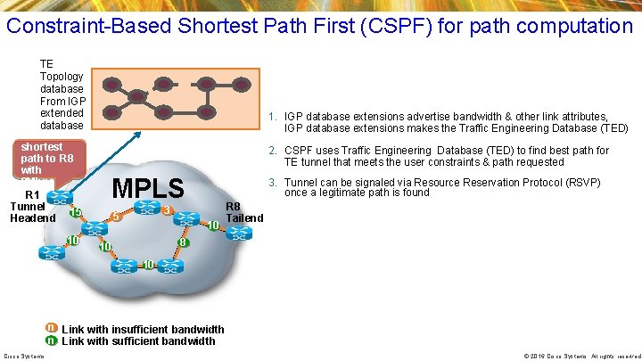
Constraint-Based Shortest Path First (CSPF) for path computation TE Topology database From IGP extended database Find shortest path to R 8 with 8 Mbps R 1 Tunnel 15 Headend 10 1. IGP database extensions advertise bandwidth & other link attributes, IGP database extensions makes the Traffic Engineering Database (TED) 2. CSPF uses Traffic Engineering Database (TED) to find best path for TE tunnel that meets the user constraints & path requested MPLS 3. Tunnel can be signaled via Resource Reservation Protocol (RSVP) once a legitimate path is found 3 5 10 R 8 Tailend 8 10 10 n Link with insufficient bandwidth n Link with sufficient bandwidth Cisco Systems © 2016 Cisco Systems. All rights reserved.
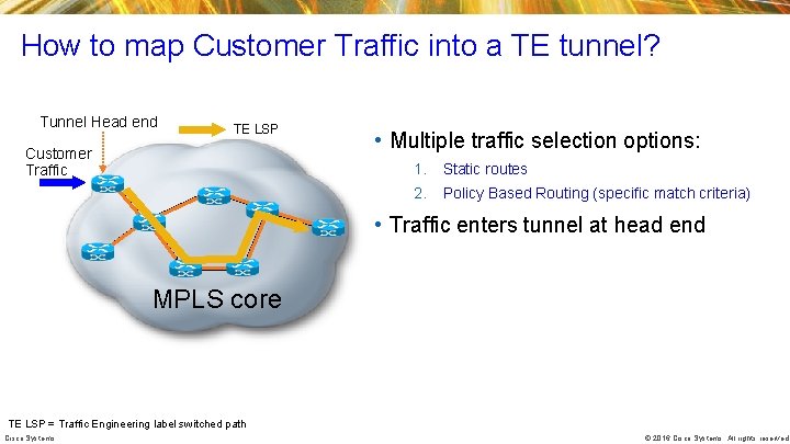
How to map Customer Traffic into a TE tunnel? Tunnel Head end TE LSP Customer Traffic • Multiple traffic selection options: 1. Static routes 2. Policy Based Routing (specific match criteria) • Traffic enters tunnel at head end MPLS core TE LSP = Traffic Engineering label switched path Cisco Systems © 2016 Cisco Systems. All rights reserved.
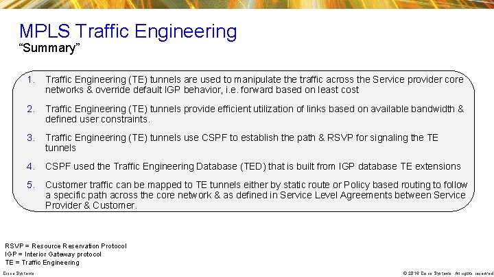
MPLS Traffic Engineering “Summary” 1. Traffic Engineering (TE) tunnels are used to manipulate the traffic across the Service provider core networks & override default IGP behavior, i. e. forward based on least cost 2. Traffic Engineering (TE) tunnels provide efficient utilization of links based on available bandwidth & defined user constraints. 3. Traffic Engineering (TE) tunnels use CSPF to establish the path & RSVP for signaling the TE tunnels 4. CSPF used the Traffic Engineering Database (TED) that is built from IGP database TE extensions 5. Customer traffic can be mapped to TE tunnels either by static route or Policy based routing to follow a specific path across the core network & as defined in Service Level Agreements between Service Provider & Customer. RSVP = Resource Reservation Protocol IGP = Interior Gateway protocol TE = Traffic Engineering Cisco Systems © 2016 Cisco Systems. All rights reserved.
MPLS Next Generation Technologies Cisco Confidential 23
Agenda • Motivation for Next Generation MPLS technologies • Application Engineered routing Summary Cisco Systems © 2016 Cisco Systems. All rights reserved.
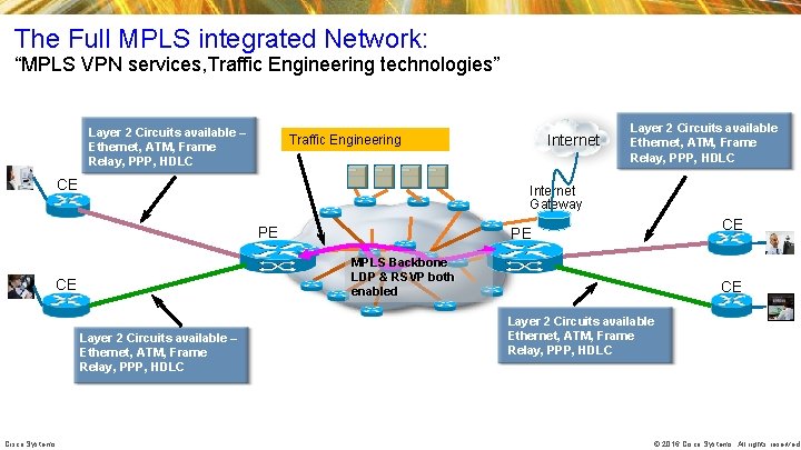
The Full MPLS integrated Network: “MPLS VPN services, Traffic Engineering technologies” Layer 2 Circuits available – Ethernet, ATM, Frame Relay, PPP, HDLC CE Layer 2 Circuits available Ethernet, ATM, Frame Relay, PPP, HDLC Internet Gateway PE CE PE MPLS Backbone LDP & RSVP both enabled CE Layer 2 Circuits available – Ethernet, ATM, Frame Relay, PPP, HDLC Cisco Systems Internet Traffic Engineering CE Layer 2 Circuits available Ethernet, ATM, Frame Relay, PPP, HDLC © 2016 Cisco Systems. All rights reserved.
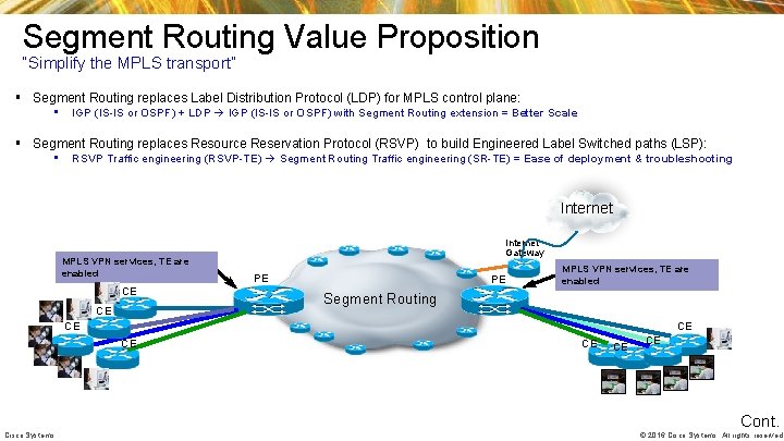
Segment Routing Value Proposition “Simplify the MPLS transport” § Segment Routing replaces Label Distribution Protocol (LDP) for MPLS control plane: • IGP (IS-IS or OSPF) + LDP IGP (IS-IS or OSPF) with Segment Routing extension = Better Scale § Segment Routing replaces Resource Reservation Protocol (RSVP) to build Engineered Label Switched paths (LSP): • RSVP Traffic engineering (RSVP-TE) Segment Routing Traffic engineering (SR-TE) = Ease of deployment & troubleshooting Internet MPLS VPN services, TE are enabled CE CE Internet Gateway PE PE MPLS VPN services, TE are enabled Segment Routing CE CE CE Cisco Systems CE CE CE Cont. © 2016 Cisco Systems. All rights reserved.
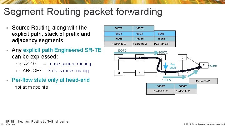
Segment Routing packet forwarding § § Source Routing along with the explicit path, stack of prefix and adjacency segments Any explicit path Engineered SR-TE can be expressed: e. g. ACOZ – Loose source routing or ABCOPZ– Strict source routing § Per-flow state only at head-end not at midpoints SR-TE = Segment Routing traffic Engineering Cisco Systems 16072 9003 16065 Packet to Z 16072 A 16072 B C D Pop 9003 M N O Z 16065 Packet to Z © 2016 Cisco Systems. All rights reserved.
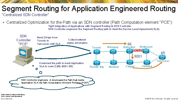
Segment Routing for Application Engineered Routing “Centralized SDN Controller” § Centralized Optimization for the Path via an SDN controller (Path Computation element “PCE”): ü Tight Integration of Applications with Segment Routing & SDN Controller ü SDN Controller engineers the Segment Routing path to meet the Service Level Agreement (SLA) SDN Controller “PCE” Need 2 Gbps from Toronto to Vancouver with SLA Collect network status information Toronto Winnipeg 66 Edmonton Whitecourt Congested 65 9001 Download the path to meet Application SLA to node Z {66, 9001, 65} Vancouver Thunder Bay Montreal Calgary Kelowna SDN Controller engineers & downloads the Path that meets Application SLA via Path Computation Element Protocol (PCEP) SDN= Software Defined Networking SLA = Service Level Agreement Cisco Systems © 2016 Cisco Systems. All rights reserved.
MPLS session Key Takeaways 1. MPLS networks consist of PE routers at ingress/egress and P routers in the core 2. MPLS forwarding operations is based on MPLS labels, hence it speeds up the performance 3. Label Distribution Protocol (LDP) is used for MPLS signaling & assigning MPLS labels to IP addresses (prefixes) 4. Routing protocols (OSPF or IS-IS ) enabled in the core network has to be working properly for proper MPLS forwarding operation 5. Traffic Engineering manipulates that path of traffic to better utilize bandwidth & meet Service Level agreements between Service Provider & Customer 6. Resource Reservation Protocol (RSVP) is used for Traffic Engineering signaling & setup 7. MPLS & its associated technologies are widely deployed across both Service Provider & Enterprise networks Cisco Systems OSPF = Open Shortest Path First IS-IS = Intermediate System to Intermediate System 29 © 2016 Cisco Systems. All rights reserved.
Thank you.
Acronyms Acronym Description MPLS Multi Protocol label switching IS-IS Intermediate system to intermediate system TE Traffic Engineering VPN Virtual Private Network LSR Label switch router ATM Asynchronous transfer mode LER Label edge router FR Frame relay CSPF Constraint-based shortest path first IP Internet protocol PBR Policy based routing FEC Forwarding equivalence class PW Pseudo wire LDP Label distribution protocol VPLS Virtual private LAN service LSP Label switched path VPWS Virtual private wire service TOS Type of service EVPN Ethernet Virtual Private Network RSVP Resource reservation protocol OAM Operation, administration, maintenance PBB-EVPN Provider backbone bridging Ethernet Virtual Private Network BGP Border gateway protocol PSN Packet Switched network VLAN Virtual local area network TTL Time to live HDLC High-level data link control Qo. S Quality of service PPP Point-to-point protocol IGP Interior gateway protocol OSPF Open shortest path first RIPv 2 Routing information protocol version 2 MAC Media Access Control EIGRP Enhanced Interior Gateway Routing Protocol LAC Link Admission Control OAM Operation, Administration & Maintenance Cisco Systems 31 © 2016 Cisco Systems. All rights reserved.