MPCSampleSystem Software Simplifies Design and Layout of Reallife


 on the Layout Grid B. Select this icon in the")


- Slides: 19
MPC-Sample-System Software Simplifies Design and Layout of Real-life Ne. SSI Systems John J. Wawrowski and David M. Simko Swagelok Company IFPAC SM 2005 Nineteenth International Forum Process Analytical Technology IFPAC January 10 -13, 2005 MPC Sample System Arlington, Virginia (Washington, D. C. ) U. S. A. 6/17/04 1 MPC-Sample-System 10
MPC-Sample-System Agenda • Review of configurator features and functionality • Live configuration of an actual system IFPAC MPC Sample System 2 6/17/04 MPC-Sample-System 10
MPC-Sample-System P&ID for Sample System To Analyzer Particle Filter, 2 Micron Pressure Gauge, 0 -30 psig PG Rotameter, Brooks, 0 -10 cc/min Pressure Regulator, 0 -15 psig Needle Valve, DK Series Pneumatic Valve, NC Check Valve, crack 0 -3 psi Needle Valve, DK Series Check Valve, crack 0 -3 psi QC Supply Sample In from Process MPC Sample System 3 6/17/04 MPC-Sample-System 10
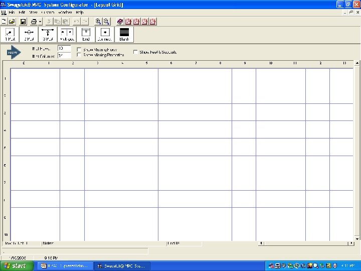
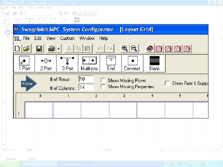
Step 1: Create Configurator Layout Grid A. File -> New PG IFPAC
Step 2: Place inlet(s) on the Layout Grid B. Select this icon in the Toolbox… PG C. Then Drag it onto the Grid IFPAC A. To add these inlets…
Step 3: Add Surface Mount Positions C. Then Drag it onto the Grid PG A. To Add this part… IFPAC B. Select this icon in the Toolbox…
Step 4 – Place outlets on Grid A. To add this outlet… C. Then Drag it onto the Grid PG IFPAC B. Select this icon in the Toolbox…
Current View after Step 4 IFPAC
Step 5: Define Surface Mount Properties B. Right click here and select Properties. A. To Select this part. . . PG C. To select a check valve… D. Left click to select category here. IFPAC
Current View after Step 5 IFPAC
Step 6: Connect Flow Paths PG A. Left click starting node… IFPAC B. Valid flow path targets are displayed as green circles.
Current View after Step 6 IFPAC
Step 7: Final Layout, BOM, and Assembly Diagram IFPAC
Step 8 – Save the File A. File -> Save PG IFPAC
Configurator Demonstration IFPAC
Conclusion • Please visit us at Booths 315/317 – Complimentary copy of the software – Opportunity to use it – Opportunity to build a Ne. SSI system IFPAC