MPAR Multifunction Phased Array Radar MultiPurpose Airport Radar


 Maximum Range for Detection")
 Methodology")
 Registration Errors")
 Registration Errors Range")


 The radiated")

. In addition to the information pulses provided, a special")


- Slides: 23
MPAR Multifunction Phased Array Radar Multi-Purpose Airport Radar
ATC History 1970 1980 1990 Discrete Address Beacon System Mode S Surveillance and Communications Microwave Landing System Beacon Collision Avoidance System TCAS Moving Target Detector Communication, Navigation and Surveillance ASR-9 Mode S Surface Comms Automation Weather 2000 UAS Airport Surface Detection Equipment SLEP Proc. Augmentation Card Parallel Runway Monitor GPS Applications Runway Status Lights ADS-B Airport Surface GCNSS/SWIM Traffic Automation Terminal ATC Automation NASA ATM Research Storm Turbulence Terminal Doppler Weather Radar SLEP ASR-9 Wind Shear Processor NEXRAD Enhancements Multi Function Phased Array Radar Integrated Terminal Weather System Aviation Weather Research Wake Vortex Corridor Integrated Weather System
ATC Real-Time Database Collision avoidance Flight plans update Radar Conflict resolution GPS Radar Track data Restriction avoidance Controller displays Real time database Autovoice advisory Terrain avoidance Weather status Terminal conditions Aircraft data Pilot 3
National Air Surveillance Infrastructure Future Today ASR-9 ASR-8 ARSR-1/2 ARSR-3 NEXRAD ASR-11 ADS-B ARSR-4 TDWR FAA transition to Automatic Dependent Surveillance Broadcast (ADS-B) dictates that the nation re-think its overall surveillance architecture. Needs: Weather (national scale and at airports) ADS-B integrity verification and backup Airspace situational awareness for homeland security MPAR
Today’s Operational Radar Capabilities Function Terminal Area Aircraft Surveillance (ASR-9/11) Maximum Range for Detection of 1 m 2 Target 60 nmi En Route Aircraft Surveillance (ARSR-4) 205 nmi Airport Weather (TDWR) 212 nmi Nationwide Weather (NEXRAD) 225 nmi Required Coverage Range 60 nm 250 nm 60 nmi 250 nmi Altitude Angular Resol. Az El 20, 000' 5 o >18 pulses PRI ~ 0. 001 sec 5 sec 2. 0 >10 pulses PRI ~ 0. 001 sec 12 sec 0. 5 ~50 pulses PRI ~ 0. 001 sec 180 sec 1 ~50 pulses PRI ~ 0. 001 sec >240 sec 60, 000' 20, 000' 50, 000' 1. 4 1 1 Scan Period Waveform* Weather surveillance drives requirements for radar power and aperture size Aircraft surveillance functions can be provided “for free” if necessary airspace coverage and update rates can be achieved Active array radar an obvious approach, but only if less expensive and/or more capable than “conventional” alternatives
Required Surveillance Performance (RSP) Methodology
RSP Derived from En Route Radar Capabilities* Currently Acceptable (sliding window SSR) Registration Errors Range Errors Latest Technology (monopulse SSR) Location Bias 200’ uniform any direction Azimuth Bias 0. 3 uniform Radar Bias 30’ uniform Radar Jitter = 25’ Gaussian = 0. 230 = 0. 068 Azimuth Error Azimuth Jitter Data Quant. (CD 2 format) Range 760’ (1/8 NM) Azimuth 0. 088 (1 ACP) Uncorrelated* Sensor Scan Time Error 10 -12 sec Transponder Error Range Error (ATCRBS) 250’ uniform = 144’ Location Error RSP Analysis *Only applies for multiple sensors Separation Errors (at 200 NM @ 600 kts) = 1. 0 NM 0. 30 NM = 0. 8 NM = 0. 25 NM 90% < 1. 4 NM 99% < 2. 4 NM 99. 9% < 3. 3 NM 90% < 0. 43 NM 99% < 0. 76 NM 99. 9% < 1. 02 NM *Supports 5 nmi separation
RSP Derived from Terminal Radar Capabilities* Currently Acceptable (sliding window SSR) Registration Errors Range Errors Intermediate (primary radar) Location Bias 200’ uniform any direction Azimuth Bias 0. 3 uniform Radar Bias 30’ uniform Latest Technology (monopulse SSR) Radar Jitter = 25’ Gaussian = 275’ Gaussian = 25’ Gaussian Azimuth Error Azimuth Jitter = 0. 230 = 0. 160 = 0. 068 Data Quant. (CD 2 format) Range 95’ (1/64 NM) Azimuth 0. 088 (1 ACP) Uncorrelated* Sensor Scan Time Error 4 -5 sec Transponder Error Range Error (ATCRBS) 250’ uniform = 144’ N/A 250’ uniform = 144’ Location Error = 0. 20 NM 0. 15 NM 0. 10 NM = 0. 16 NM at 40 nm = 0. 12 NM at 40 nm = 0. 08 NM at 60 nm 90% < 0. 28 NM 99% < 0. 49 NM 99. 9% < 0. 65 NM 90% < 0. 20 NM 99% < 0. 35 NM 99. 9% < 0. 46 NM 90% < 0. 13 NM 99% < 0. 23 NM 99. 9% < 0. 32 NM RSP Analysis *Only applies for multiple sensors Separation Errors (at specified range @ 250 kts) *Supports 3 nmi separation
MPAR RSP Analysis 20: 1 Monopulse 4. 4 antenna beamwidth meets Terminal RSP Separation Error 4. 6 antenna beamwidth meets En Route RSP Separation Error
Concept MPAR Parameters Aircraft Surveillance • Diameter: 8 m TR elements/face: 20, 000 Dual polarization Beamwidth: 0. 7 (broadside) 1. 0 (@ 45 ) Gain: > 46 d. B • Weather Surveillance Transmit/Receive Modules Wavelength: Bandwidth/channel: Frequency channels: Pulse length: Peak power/element: Non cooperative target tracking and characterization 334 MPARS required to duplicate today’s airspace coverage. Half of these are scaled “Terminal MPARS” Active Array (planar, 4 faces) • 10 cm (2. 7– 2. 9 GHz) 1 MHz 3 30 s 2 W Architecture Overlapped subarray Number of subarrays: 300– 400 Maximum concurrent beams: ~160
Concept MPAR Capability Summary • Airspace coverage equal to today’s operational radar networks. • Angular resolution, minimum detectible reflectivity and volume scan update rate equal or exceed today’s operational weather radars – Ancillary benefits from improved data integrity and cross-beam wind measurement • Can easily support 3 -5 nmi separation standards required for ADS-B backup • Can provide non-cooperative aircraft surveillance data of significantly higher quality that today’s surveillance radars – Altitude information – Substantially lower minimum RCS threshold
SLS
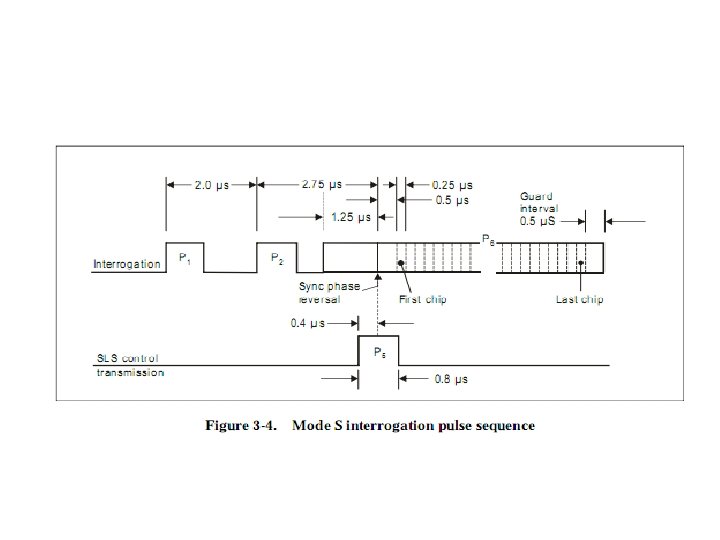
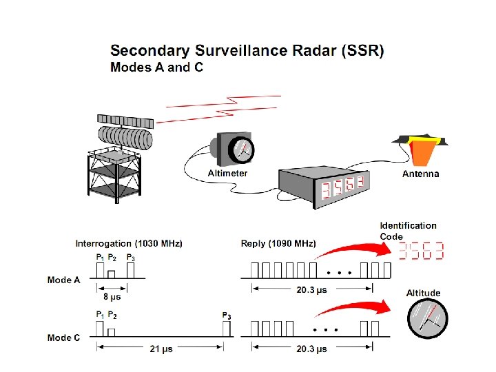
3. 1. 1. 5 INTERROGATOR AND CONTROL TRANSMISSION CHARACTERISTICS (INTERROGATION SIDE-LOBE SUPPRESSION) The radiated amplitude of P 2 at the antenna of the transponder shall be: a) equal to or greater than the radiated amplitude of P 1 from the side-lobe transmissions of the antenna radiating P 1; and b) at a level lower than 9 d. B below the radiated amplitude of P 1, within the desired arc of interrogation. Within the desired beam width of the directional interrogation (main lobe), the radiated amplitude of P 3 shall be within 1 d. B of the radiated amplitude of P 1.
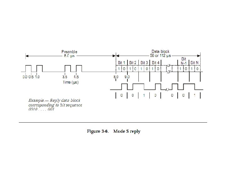
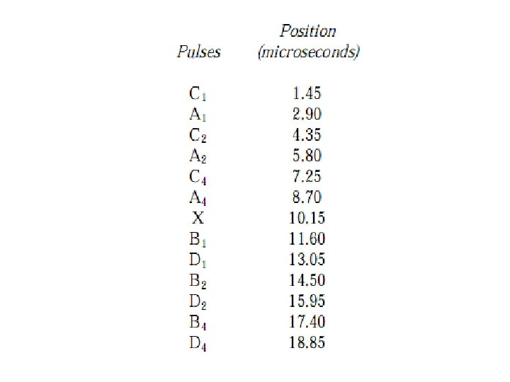
3. 1. 1. 6 REPLY TRANSMISSION CHARACTERISTICS Framing pulses. The reply function shall employ a signal comprising two framing pulses spaced 20. 3 microseconds as the most elementary code. Information pulses shall be spaced in increments of 1. 45 microseconds from the first framing pulse. The designation and position of these information pulses shall be as follows:
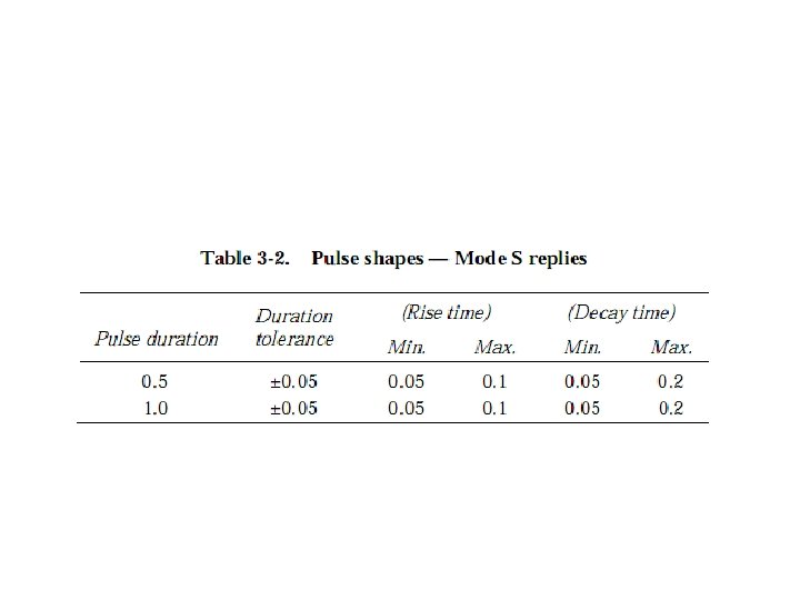
Special position identification pulse (SPI). In addition to the information pulses provided, a special position identification pulse shall be transmitted but only as a result of manual (pilot) selection. When transmitted, it shall be spaced at an interval of 4. 35 microseconds following the last framing pulse of Mode A replies only. Reply pulse shape. All reply pulses shall have a pulse duration of 0. 45 plus or minus 0. 1 microsecond, a pulse rise time between 0. 05 and 0. 1 microsecond a pulse decay time between 0. 05 and 0. 2 microsecond. The pulse amplitude variation of one pulse with respect to any other pulse in a reply train shall not exceed 1 d. B.
Code nomenclature. The code designation shall consist of digits between 0 and 7 inclusive, and shall consist of the sum of the subscripts of the pulse numbers employed as follows:
END.