Motor Control of an Oscillating Pendulum Nick Myers


 N-Channel Power Transistors The H-bridge operates")


- Slides: 23
Motor Control of an Oscillating Pendulum Nick Myers and Chirag Patel March 9, 2004 Advised by: Dr. James Irwin and Mr. Jose Sanchez Bradley University Department of Electrical Engineering and Technology
Presentation Overview • Project Objectives • System Block Diagrams • Original Schedule of Tasks to be completed • Work Completed (Nick) • Work to be Completed (Nick) • Work Completed (Chirag) • Work to be Completed (Chirag) • Revised Schedule of Tasks to be completed • Summary of Progress • Questions
Objectives To initialize the oscillation of a weighted pendulum using microprocessor controlled motor bursts. To oscillate the pendulum to a predefined angle and, using optical sensor outputs, maintain the angle of oscillation.
System Level Block Diagram
Subsystem Level Block Diagram
Schedule of Tasks
Goals Accomplished to Date n n Motor control switch to allow user to switch motor on/off H-bridge hardware to allow motor to turn in both directions H-bridge microprocessor code to switch Hbridge automatically based on pendulum location and direction Construction of our pendulum unit
H-bridge Hardware
H-bridge Hardware n n The H-bridge uses (4) N-Channel Power Transistors The H-bridge operates on a supply voltage of +15 V DC The H-bridge ideally accepts input voltages of 0 V or +15 V DC Finding the appropriate transistors to power our motor was difficult
H-bridge Microprocessor Code n n n The H-bridge will switch motor burst direction every time the pendulum passes equilibrium. Once the direction is switched, a burst will immediately be sent. The H-bridge code will be called by the sensor input interrupt.
H-bridge Microprocessor Code
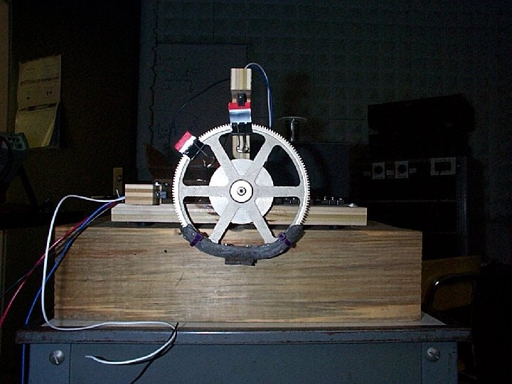
Constructed Pendulum
Goals to be Accomplished n n Complete hardware interface for EMAC to Hbridge Calculate timing for motor burst lengths to be called by H-bridge code Create timing code that will burst the motor with increasing lengths as pendulum period increases Compile H-bridge code with all other project codes
Goals Accomplished to Date n Optical Sensor with desired switching times and code to read the sensors through EMAC. n PWM Signal Code to initiate oscillation. n Pulse Width Measurement Code to control speed of oscillation n Design of Pendulum Structure
Optical Sensor n Two sensors to be used – One at equilibrium – Another at desired swing of oscillation n RF = 200 to limit current to 20 m. A – Enough current to transmit infrared signal – Not enough current to damage Optical Sensor n R 1 = 4700 to account for desired on/off switching times – ON Switching Time • 8 us * 1. 7 = 14. 4 us – OFF Switching Time • 50 us * 1. 6 = 80 us
PWM Signal n Current PWM signal = 1 khz @ 33% Duty cycle. – Actual frequency will be much smaller. n PWM signal will be used to initiate the oscillation of the pendulum. – Once pendulum is beyond the equilibrium sensor, timed pulse signals will be used to oscillate the pendulum.
Pulse Width Measurement n Pulse Width Measurement code used to measure length of time sensor is obstructed by pendulum. – This time will be used to control the length of the pulse sent to motor to control oscillation of pendulum. • Faster oscillation = Smaller pulses • Slower oscillation = Larger pulses
Goals to be Accomplished n Construct code for the timed pulses of constant length in order to sustain oscillation beyond the equilibrium sensor. n Construct code to adjust the length of the timed pulses which will be dependent upon the pulse width measurement. n Construct code to maintain oscillation once the predefined height sensor is reached.
Software Flowchart PWM SIGNAL TO INIT. OSCILLATION OUT OF EQ. ? SENSO R NO PULSE WIDTH MEASUREMENT TIMED PULSES OF LENGTH TO BE DETERMINED UPON PULSE WIDTH PRESE T SENSO R? ? MAINTAIN OSCILLATION NO
Revised Schedule of Tasks
Progress to Date n Completed motor on/off switch n Completed Optical sensor timing values and code n Completed H-bridge hardware n Completed PWM signal code n Completed pulse width measurement code n Completed pendulum construction n Completed H-bridge software n Partially completed EMAC to H-bridge interfacing
Questions?