
MOSFET VI Characteristics Vijaylakshmi B Lecturer Dept of
MOSFET V-I Characteristics Vijaylakshmi. B Lecturer, Dept of Instrumentation Tech Basaveswar Engg. College Bagalkot, Karnataka IUCEE-VLSI Design, Infosys, Mysore
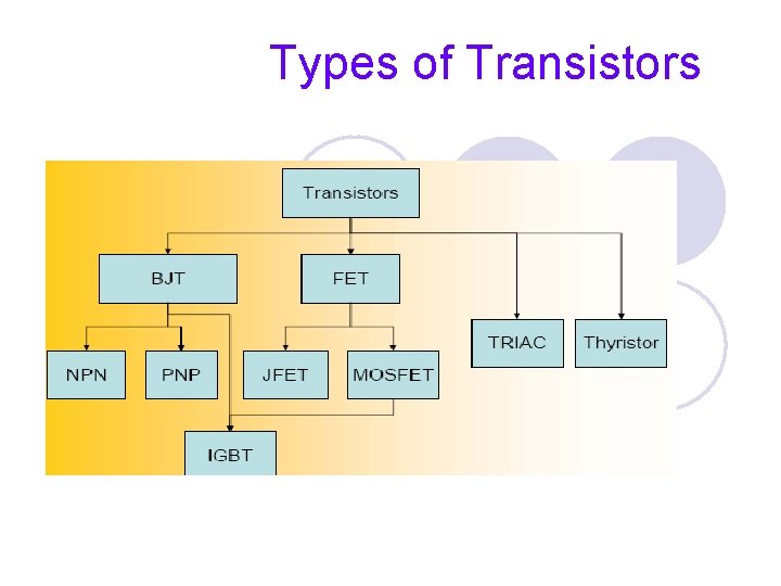
Types of Transistors
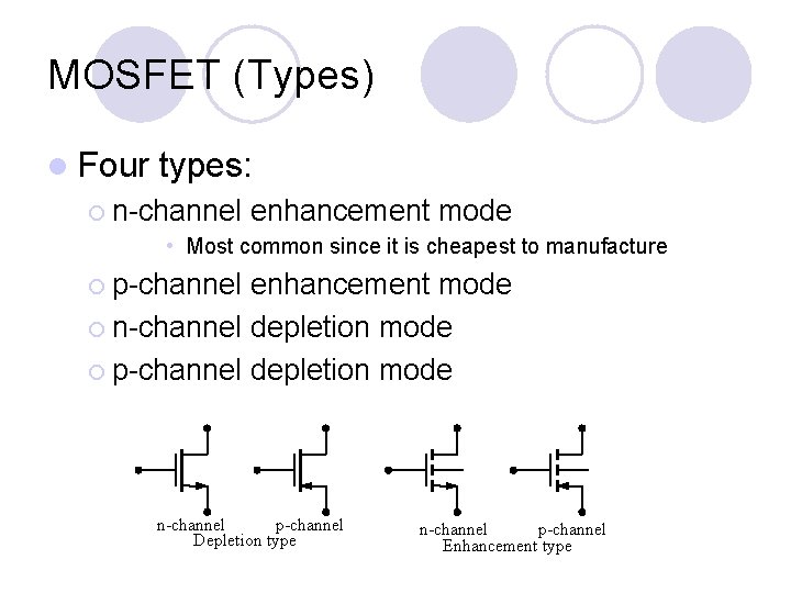
MOSFET (Types) l Four types: ¡ n-channel enhancement mode • Most common since it is cheapest to manufacture ¡ p-channel enhancement mode ¡ n-channel depletion mode ¡ p-channel depletion mode n-channel p-channel Depletion type n-channel p-channel Enhancement type
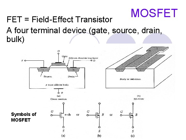
MOSFET = Field-Effect Transistor A four terminal device (gate, source, drain, bulk) Symbols of MOSFET
MOSFET characteristics Basically low voltage device. High voltage device are available up to 600 V but with limited current. Can be paralleled quite easily for higher current capability. l Internal (dynamic) resistance between drain and source during on state, RDS(ON), , limits the power handling capability of MOSFET. High losses especially for high voltage device due to RDS(ON). l Dominant in high frequency application (>100 k. Hz). Biggest application is in switchedmode power supplies. l
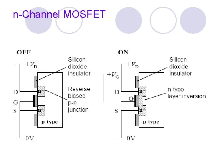
The transistor consists of three regions, labeled the ``source'', the ``gate'' and the ``drain''. l The area labeled as the gate region is actually a ``sandwich'' consisting of the underlying substrate material, which is a single crystal of semiconductor material (usually silicon); a thin insulating layer (usually silicon dioxide); and an upper metal layer. l Electrical charge, or current, can flow from the source to the drain depending on the charge applied to the gate region. l The semiconductor material in the source and drain region are ``doped'' with a different type of material than in the region under the gate, so an NPN or PNP type structure exists between the source and drain region of a MOSFET. l
• Most important device in digital design • Very good as a switch • Relatively few parasitics • Rather low power consumption • High integration density • Simple manufacturing • Economical for large complex circuits
n-Channel MOSFET
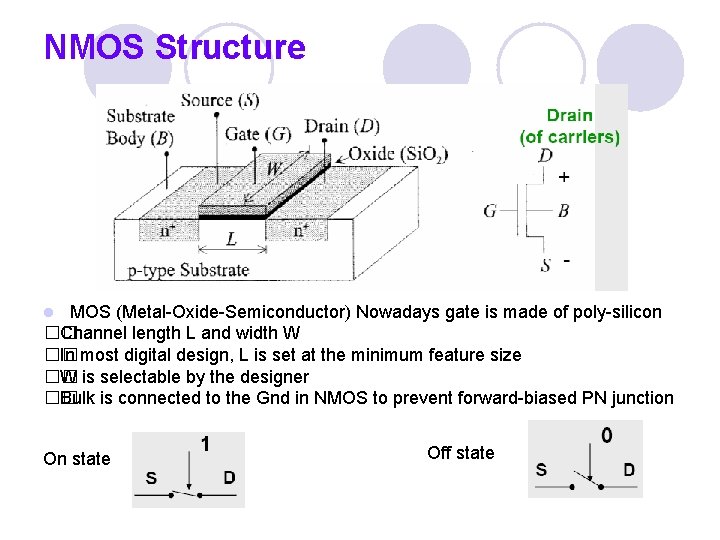
NMOS Structure MOS (Metal-Oxide-Semiconductor) Nowadays gate is made of poly-silicon �� Channel length L and width W �� In most digital design, L is set at the minimum feature size �� W is selectable by the designer �� Bulk is connected to the Gnd in NMOS to prevent forward-biased PN junction l On state Off state
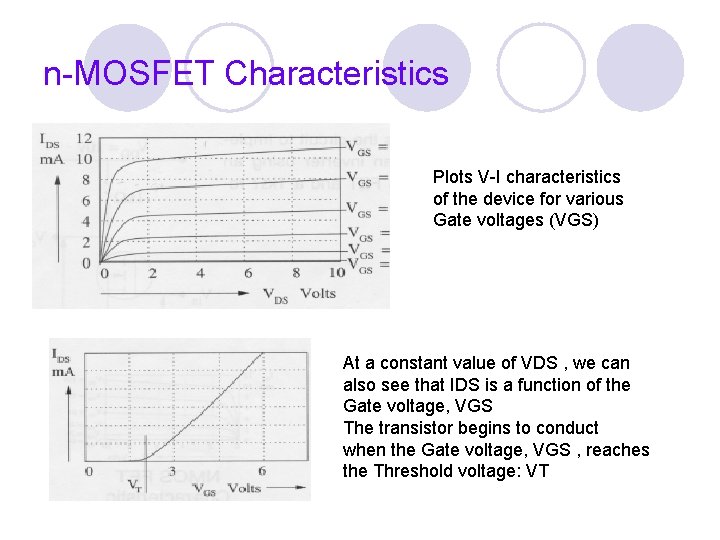
n-MOSFET Characteristics Plots V-I characteristics of the device for various Gate voltages (VGS) At a constant value of VDS , we can also see that IDS is a function of the Gate voltage, VGS The transistor begins to conduct when the Gate voltage, VGS , reaches the Threshold voltage: VT
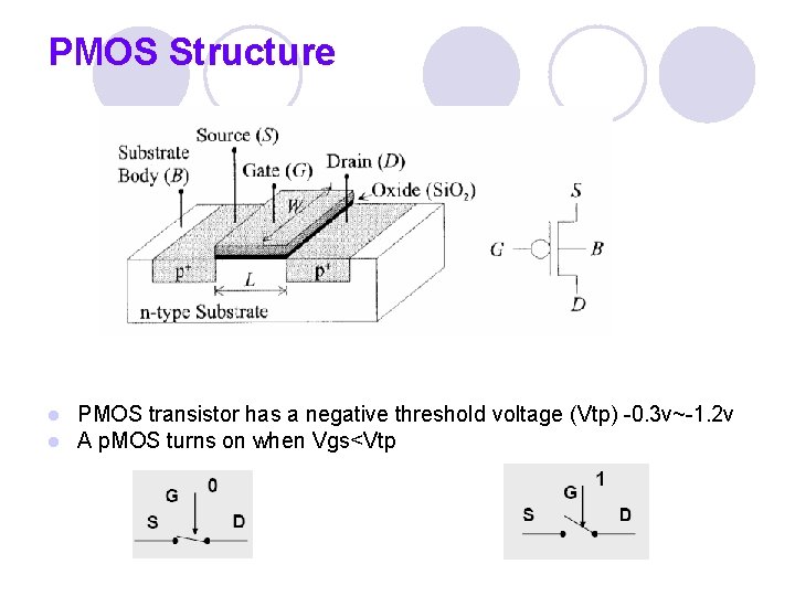
PMOS Structure l l PMOS transistor has a negative threshold voltage (Vtp) -0. 3 v~-1. 2 v A p. MOS turns on when Vgs<Vtp
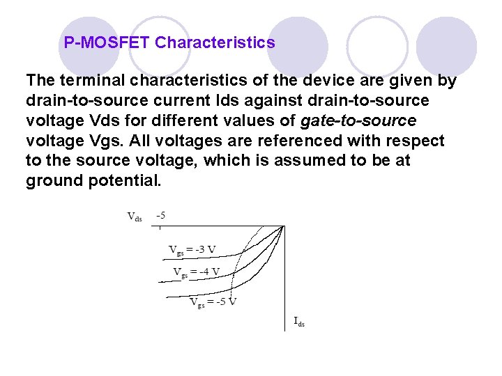
P-MOSFET Characteristics The terminal characteristics of the device are given by drain-to-source current Ids against drain-to-source voltage Vds for different values of gate-to-source voltage Vgs. All voltages are referenced with respect to the source voltage, which is assumed to be at ground potential.
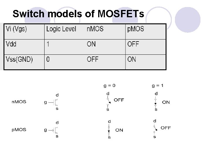
Switch models of MOSFETs

Thank You
- Slides: 14