
MOSFET Module Series 1 Comparison between Trench IGBT

MOSFET Module Series 1

Comparison between Trench IGBT and Trench MOSFET Trench IGBT G E Trench MOSFET G S P base n+ emitter n- layer n+ substrate n+ buffer layer p+ substrate C G D E S Body diode G C D 2
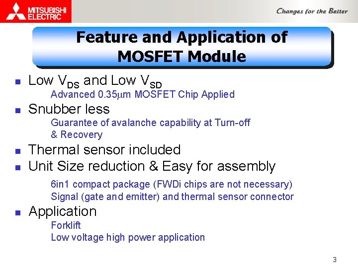
Feature and Application of MOSFET Module n Low VDS and Low VSD Advanced 0. 35 mm MOSFET Chip Applied n Snubber less Guarantee of avalanche capability at Turn-off & Recovery n n Thermal sensor included Unit Size reduction & Easy for assembly 6 in 1 compact package (FWDi chips are not necessary) Signal (gate and emitter) and thermal sensor connector n Application Forklift Low voltage high power application 3
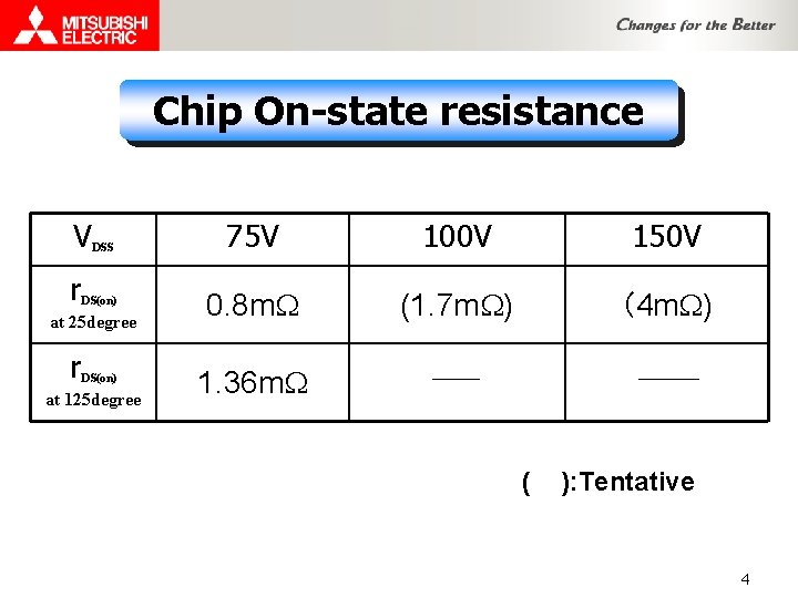
Chip On-state resistance V r DSS DS(on) at 25 degree r DS(on) at 125 degree 75 V 100 V 150 V 0. 8 m. W (1. 7 m. W) (4 m. W) 1. 36 m. W ( ): Tentative 4
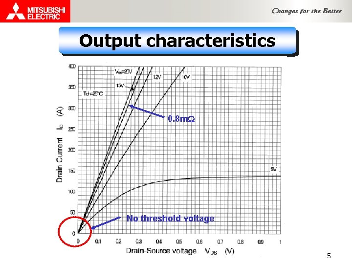
Output characteristics 0. 8 m. W No threshold voltage 5
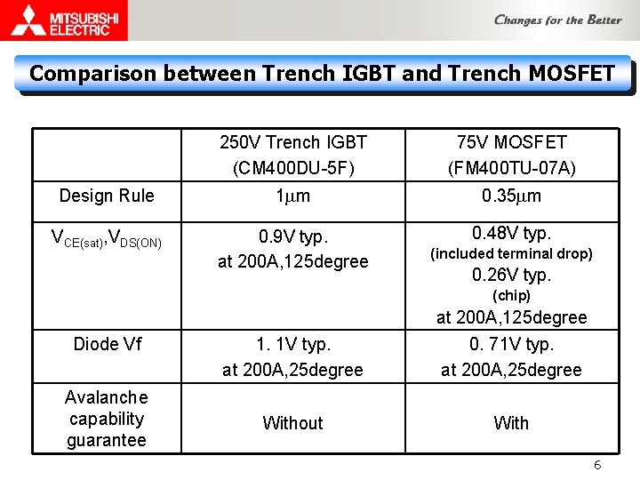
Comparison between Trench IGBT and Trench MOSFET 250 V Trench IGBT (CM 400 DU-5 F) 75 V MOSFET (FM 400 TU-07 A) Design Rule 1 mm 0. 35 mm VCE(sat), VDS(ON) 0. 9 V typ. at 200 A, 125 degree 0. 48 V typ. (included terminal drop) 0. 26 V typ. (chip) at 200 A, 125 degree Diode Vf Avalanche capability guarantee 1. 1 V typ. at 200 A, 25 degree 0. 71 V typ. at 200 A, 25 degree Without With 6

Avalanche turn-off switching waveform (FM 400 TU-07 A) Cond. VDD=48 V VGS=± 15 V Tch=125℃ Turn-off Avalanche period 175 ms ID Turn-on VDS 48 V 110 V Avalanche Energy 2. 3 J ID: 50 A/div, VDS: 50 V/div, t: 50 ms/div 7
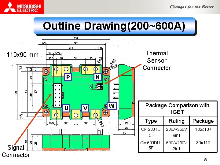
Outline Drawing(200~600 A) Thermal Sensor Connector 110 x 90 mm P U Signal Connector N V W Package Comparison with IGBT Type Rating Package CM 200 TU -5 F 200 A/250 V 6 in 1 102 x 107 CM 600 DU 5 F 600 A/250 V 2 in 1 80 x 110 8
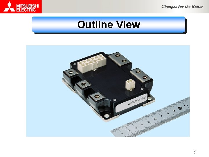
Outline View 9

Comparison with Discrete MOSFET 6 in 1 Discrete MOSFET Several 10 ~ several 100 pcs Heat sink ・・・・・ 10

Avalanche capability comparison Discrete ×(Not OK) Many paralleled MOSFET Avalanche capability not guarantee →with snubber circuit Module ◎(OK) Single MOSFET Chip Avalanche capability guarantee →without snubber Avalanche energy 11
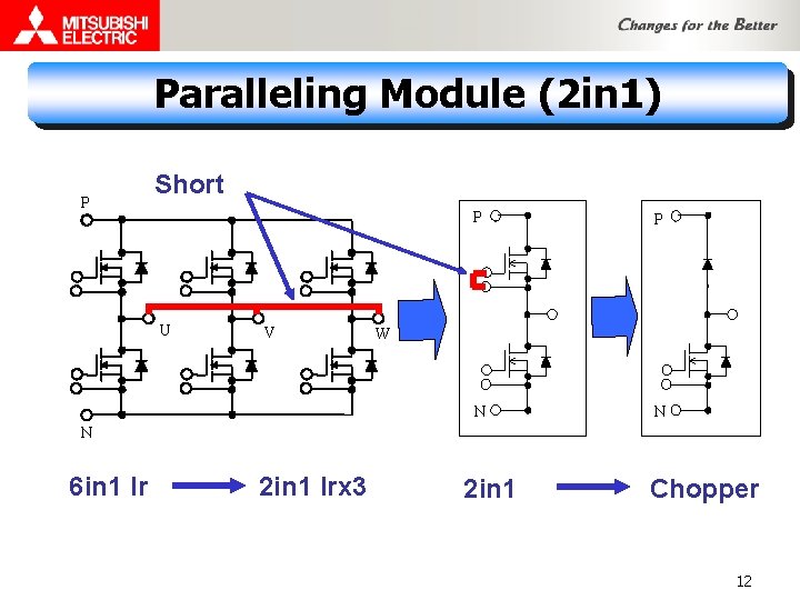
Paralleling Module (2 in 1) P Short U V P P N N W N 6 in 1 Ir 2 in 1 Irx 3 2 in 1 Chopper 12

Paralleling Circuit DC N P U V AC W 13
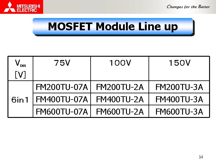
MOSFET Module Line up V [V] DSS 75 V 100 V FM 200 TU-07 A FM 200 TU-2 A 6in1 FM 400 TU-07 A FM 400 TU-2 A FM 600 TU-07 A FM 600 TU-2 A 150 V FM 200 TU-3 A FM 400 TU-3 A FM 600 TU-3 A 14

MOSFET Module Development Schedule 6 in 1 Tentative Type TS ES CS PKG FM 200 TU-07 A OK ’ 04/10 ’ 04/12 110 x 90 FM 400 TU-07 A OK OK ’ 04/11 110 x 90 FM 600 TU-07 A OK ’ 04/10 ’ 04/12 110 x 90 FM 200 TU-2 A ’ 04/11 ’ 05/3 ’ 05/6 110 x 90 FM 400 TU-2 A OK OK ’ 04/11 110 x 90 FM 600 TU-2 A ’ 04/11 ’ 05/3 ’ 05/6 110 x 90 FM 200 TU-3 A ’ 04/11 ’ 05/2 ’ 05/5 110 x 90 FM 400 TU-3 A OK ’ 04/12 ’ 05/2 110 x 90 FM 600 TU-3 A ’ 04/11 ’ 05/2 ’ 05/5 110 x 90 15
- Slides: 15