More demanding workload Design Goals More demanding workload


")
 e. g. DPDK, mtcp, libvma,")
 e. g. DPDK, mtcp, libvma,")


")
 FPGA PCIe Gen 3")
 FPGA PCIe Gen 3")
 FPGA PCIe Gen 3")


 FPGA PCIe")


 (GET / PUT) Power (Kops/W) Comment Latency (us) (GET / PUT) Memcached")
 (GET / PUT) Power (Kops/W) Comment Latency (us) (GET / PUT) Memcached")
 (GET / PUT) Power (Kops/W) Comment Latency (us) (GET / PUT) Memcached")


- Slides: 51
More demanding workload
Design Goals ____ More demanding workload
Bottleneck: Network stack in OS (~300 Kops per core)
Bottleneck: Network stack in OS (~300 Kops per core) e. g. DPDK, mtcp, libvma, two-sided RDMA Bottlenecks: CPU random memory access and KV operation computation (~5 Mops per core)
Bottleneck: Network stack in OS (~300 Kops per core) e. g. DPDK, mtcp, libvma, two-sided RDMA Bottlenecks: CPU random memory access and KV operation computation (~5 Mops per core) Communication overhead: multiple roundtrips per KV operation (fetch index, data) Synchronization overhead: write operations
Offload KV processing on CPU to Programmable NIC
QPI CPU FPGA QSFP 40 Gb/s To. R
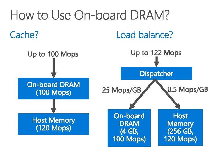
NIC On-board DRAM PCIe (host mem)
40 Gb. E To. R switch On-board DRAM (4 GB) FPGA PCIe Gen 3 x 16 DMA Host DRAM (256 GB)
40 Gb. E To. R switch On-board DRAM (4 GB) FPGA PCIe Gen 3 x 16 DMA Header overhead and limited parallelism: 13 GB/s Be frugal on 120 Mops memory accesses Host DRAM (256 GB)
40 Gb. E To. R switch On-board DRAM (4 GB) FPGA PCIe Gen 3 x 16 DMA Atomic operations have dependency: 1 us delay 120 Mops PCIe latency hiding Host DRAM (256 GB)
40 Gb. E To. R switch 0. 2 us delay 100 Mops On-board DRAM (4 GB) Load dispatch FPGA PCIe Gen 3 x 16 DMA 1 us delay 120 Mops Host DRAM (256 GB)
60 Mpps 40 Gb. E To. R switch 0. 2 us delay 100 Mops On-board DRAM (4 GB) Client-side batching Vector-type operations FPGA PCIe Gen 3 x 16 DMA 1 us delay 120 Mops Host DRAM (256 GB)
Hide memory access latency Leverage throughput of both on-board and host memory 4. Offload simple client computation to server 2. 3.
New free slab Adjacent slab to check
32 B stack Host Daemon Merger Hashtable 512 B stack NIC side Sync 512 B stack Splitter Host side
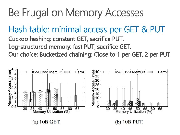
Be frugal on memory accesses for both GET and PUT 2. Hide memory access latency 3. Leverage throughput of both on-board and host memory 4. Offload simple client computation to server 1.
K 1 += a K 1 += b K 1 unlocked
K 1 += a K 1 += b K 1 cached Execute in cache
K 1 += a K 1 += b K 2 += c Stalled due to K 1
K 1 += a K 1 += b K 2 += c OOO execution Reordered response
We hope future RDMA NICs could adopt out-of-order execution for atomic operations!
Be frugal on memory accesses for both GET and PUT 2. Hide memory access latency 3. Leverage throughput of both on-board and host memory 4. Offload simple client computation to server 1.
40 Gb. E To. R switch 100 Mops On-board DRAM (4 GB) FPGA PCIe Gen 3 x 16 DMA 120 Mops Host DRAM (256 GB)
184 Mops 92 Mops 64 Mops 28 Mops 92 Mops 120 Mops Make full use of both on-board and host DRAM by adjusting the cache-able portion
Be frugal on memory accesses for both GET and PUT 2. Hide memory access latency 3. Leverage throughput of both on-board and host memory 4. Offload simple client computation to server 1.
Approach 1: Each element as a key Approach 2: Compute at client
Approach 1: Each element as a key Approach 2: Compute at client Our approach: Vector operations
10 9 8 7 6 5 4 3 2 1 0 Min latency Avg latency Batching Max latency Non-batching
CPU Random performance memory access KV-Direct NIC 14. 4 GB/s idle On-board FPGA DRAM (4 GB) NIC 14. 4 GB/s KV-Direct busy PCIe Gen 3 x 16 DMA Sequential 40 Gb. E memory To. R switch access 60. 3 GB/s 55. 8 GB/s 13 GB/s 120 Mops Run other tasks on CPU Host DRAM (64 GB KVS, 192 GB other) 100 GB/s 600 Mops
1. 22 billion KV op/s 357 watts power
Tput (Mops) (GET / PUT) Power (Kops/W) Comment Latency (us) (GET / PUT) Memcached 1. 5 / 1. 5 5/5 TCP/IP 50 / 50 Mem. C 3 4. 3 / 4. 3 14 / 14 TCP/IP 50 / 50 RAMCloud 6/1 20 / 3. 3 Kernel bypass 5 / 14 MICA (12 NICs) 137 / 135 342 / 337 Kernel bypass 81 / 81 FARM 6/3 30 (261) / 15 One-side RDMA 4. 5 / 10 Dr. TM-KV 115 / 14 500 (3972) / 60 One-side RDMA 3. 4 / 6. 3 HERD 35 / 25 490 / 300 Two-side RDMA 4 / 4 FPGA-Xilinx 14 / 14 106 / 106 FPGA 3. 5 / 4. 5 Mega-KV 166 / 80 330 / 160 GPU 280 / 280 KV-Direct (1 NIC) 180 / 114 1487 (5454) / 942 (3454) Programmable NIC 4. 3 / 5. 4 KV-Direct (10 NICs) 1220 / 610 3417 (4518) / 1708 (2259) Programmable NIC 4. 3 / 5. 4 * Number in parenthesis indicates power efficiency based on power consumption of NIC only, for server-bypass systems.
Tput (Mops) (GET / PUT) Power (Kops/W) Comment Latency (us) (GET / PUT) Memcached 1. 5 / 1. 5 5/5 TCP/IP 50 / 50 Mem. C 3 4. 3 / 4. 3 14 / 14 TCP/IP 50 / 50 RAMCloud 6/1 20 / 3. 3 Kernel bypass 5 / 14 MICA (12 NICs) 137 / 135 342 / 337 Kernel bypass 81 / 81 FARM 6/3 30 (261) / 15 One-side RDMA 4. 5 / 10 Dr. TM-KV 115 / 14 500 (3972) / 60 One-side RDMA 3. 4 / 6. 3 HERD 35 / 25 490 / 300 Two-side RDMA 4 / 4 FPGA-Xilinx 14 / 14 106 / 106 FPGA 3. 5 / 4. 5 Mega-KV 166 / 80 330 / 160 GPU 280 / 280 KV-Direct (1 NIC) 180 / 114 1487 (5454) / 942 (3454) Programmable NIC 4. 3 / 5. 4 KV-Direct (10 NICs) 1220 / 610 3417 (4518) / 1708 (2259) Programmable NIC 4. 3 / 5. 4 * Number in parenthesis indicates power efficiency based on power consumption of NIC only, for server-bypass systems.
Tput (Mops) (GET / PUT) Power (Kops/W) Comment Latency (us) (GET / PUT) Memcached 1. 5 / 1. 5 5/5 TCP/IP 50 / 50 Mem. C 3 4. 3 / 4. 3 14 / 14 TCP/IP 50 / 50 RAMCloud 6/1 20 / 3. 3 Kernel bypass 5 / 14 MICA (12 NICs) 137 / 135 342 / 337 Kernel bypass 81 / 81 FARM 6/3 30 (261) / 15 One-side RDMA 4. 5 / 10 Dr. TM-KV 115 / 14 500 (3972) / 60 One-side RDMA 3. 4 / 6. 3 HERD 35 / 25 490 / 300 Two-side RDMA 4 / 4 FPGA-Xilinx 14 / 14 106 / 106 FPGA 3. 5 / 4. 5 Mega-KV 166 / 80 330 / 160 GPU 280 / 280 KV-Direct (1 NIC) 180 / 114 1487 (5454) / 942 (3454) Programmable NIC 4. 3 / 5. 4 KV-Direct (10 NICs) 1220 / 610 3417 (4518) / 1708 (2259) Programmable NIC 4. 3 / 5. 4 * Number in parenthesis indicates power efficiency based on power consumption of NIC only, for server-bypass systems.
QPI CPU FPGA QSFP 40 Gb/s To. R
Go beyond the memory wall & reach a fully programmable world
Back-of-envelope calculations show potential performance gains when KV-Direct is applied in end-toend applications. In Page. Rank, because each edge traversal can be implemented with one KV operation, KV -Direct supports 1. 2 billion TEPS on a server with 10 programmable NICs. In comparison, GRAM (Ming Wu on So. CC’ 15) supports 250 M TEPS per server, bounded by interleaved computation and random memory access.
The discussion section of the paper discusses NIC hardware with different capacity. First, the goal of KVDirect is to leverage existing hardware in data centers instead of designing a specialized hardware to achieve maximal KVS performance. Even if future NICs have faster or larger on-board memory, under long-tail workload, our load dispatch design still shows performance gain. The hash table and slab allocator design is generally applicable to cases where we need to be frugal on memory accesses. The out-of-order execution engine can be applied to all kinds of applications in need of latency hiding.
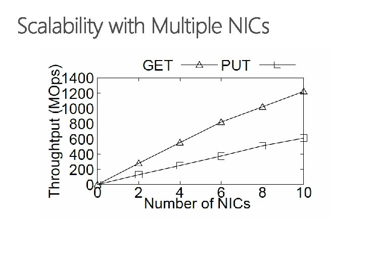
With a single KV-Direct NIC, the throughput is equivalent to 20 to 30 CPU cores. These CPU cores can run other CPU intensive or memory intensive workload, because the host memory bandwidth is much larger than the PCIe bandwidth of a single KV-Direct NIC. So we basically save tens of CPU cores per programmable NIC. With ten programmable NICs, the throughput can grow almost linearly.
Each NIC behaves as if it is an independent KV-Direct server. Each NIC serves a disjoint partition of key space and reserves a disjoint region of host memory. The clients distribute load to each NIC according to the hash of keys, similar to the design of other distributed keyvalue stores. Surely, the multiple NICs suffer load imbalance problem in long-tail workload, but the load imbalance is not significant with a small number of partitions. The Net. Cache system in this session can also mitigate the load imbalance problem.
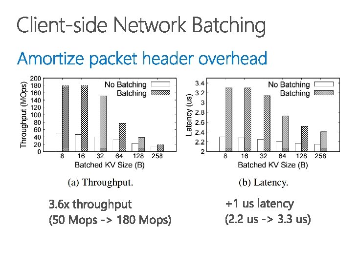
We use client-side batching because our programmable NIC has limited network bandwidth. The network bandwidth is only 5 GB/s, while the DRAM and PCIe bandwidth are both above 10 GB/s. So we batch multiple KV operations in a single network packet to amortize the packet header overhead. If we have a higher bandwidth network, we will no longer need network batching.