Modulus Randomization Basic Noise Shaping HigherOrder Noise Shaping

ﻧﻤﺎی کﻠی ﻓﺼﻞ ﺗﺼﺎﺩﻓی ﺳﺎﺯی ﻭ ﺷکﻞ ﺩﻫی ﻧﻮیﺰ ü ü ü Modulus Randomization Basic Noise Shaping Higher-Order Noise Shaping Out-of-Band Noise Charge Pump Mismatch Chapter 11 Fractional -N Synthesizers کﺎﻫﺶ ﻧﻮیﺰ کﻮﺍﻧﺘﺶ ü ü DAC Feedforward Fractional Divider Reference Doubling Multi-Phase Division 2
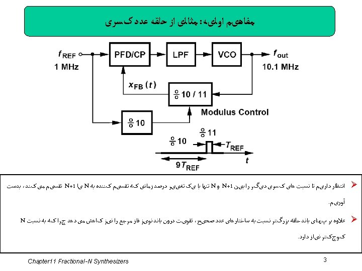
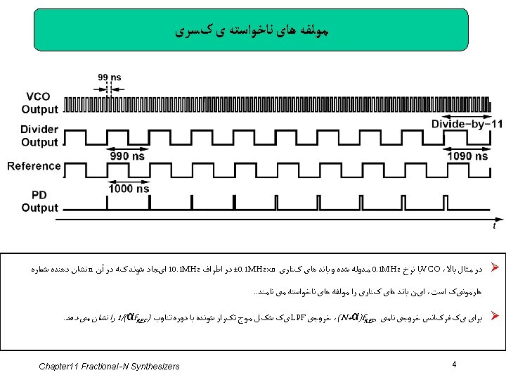
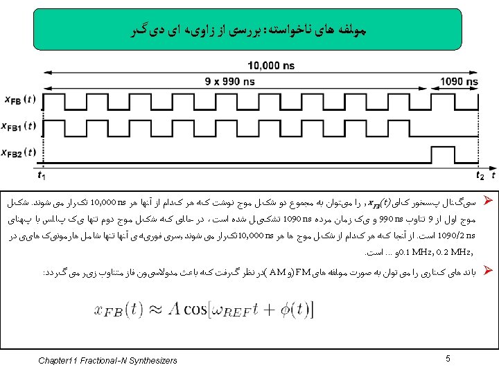

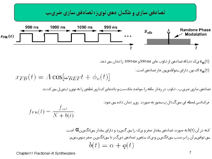
ﻃیﻒ ﻣﻮﻟﻔﻪ ﻫﺎی ﻧﺎﺧﻮﺍﺳﺘﻪ کﺴﺮی : ﻣﺜﺎﻝ Determine the spectrum of x. FB 1(t) in figure below. Solution: Let us first find the Fourier transform of one period of the waveform (from t 1 to t 2). This waveform consists of nine 990 -ns cycles. If we had an infinite number of such cycles, the Fourier transform would contain only harmonics of 1. 01 MHz. With nine cycles, the energy is spread out of the impulses. If this waveform is repeated every 10 μs, its Fourier transform is multiplied by a train of impulses located at integer multiples of 0. 1 MHz. The spectrum thus appears as shown in figure below. Chapter 11 Fractional -N Synthesizers 6
 and q(t) as a function of time.")
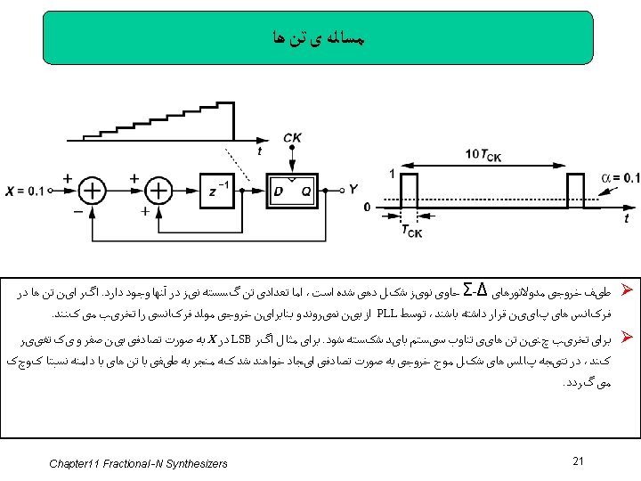
ﺗﺼﺎﺩﻓی ﺳﺎﺯی : ﻣﺜﺎﻝ Plot b(t) and q(t) as a function of time. The sequence b(t) contains an occasional square pulse so that the average is α. Subtracting α from b(t) yields the noise waveform, q(t). If q(t) << N + α, we have The feedback waveform arriving at the PFD Phase noise given by: Chapter 11 Fractional -N Synthesizers 8

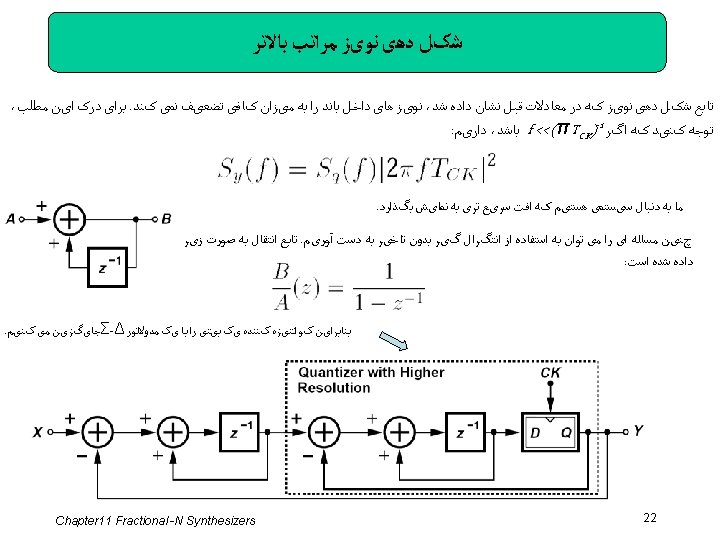
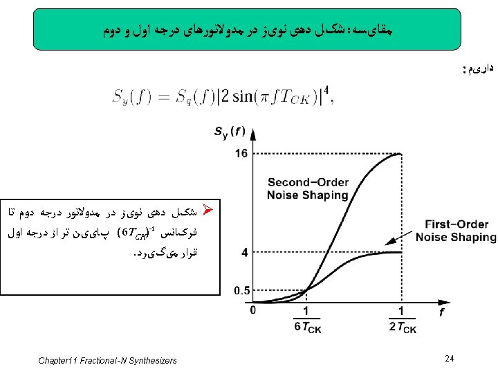
ﻣﺜﺎﻟی ﺍﺯ ﻧﻮیﺰ ﻓﺎﺯ Plot the previous formulated phase noise a function of time. With the aid of the wave form obtained last Example for q(t), we arrive at the random triangular waveform shown below: Determine the spectrum of ϕn, div(t). The time integral of a function leads to a factor of 1/s in the frequency domain. Thus, the power spectral density of q(t) must be multiplied by [2 π fout / (N + α)2 / ω] 2, where Sq(f) is the spectrum of the quantization noise, q(t). Note that this noise can be “referred” to the other PFD input—as if it existed in the reference waveform rather than the divider output. Chapter 11 Fractional -N Synthesizers 9

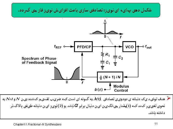
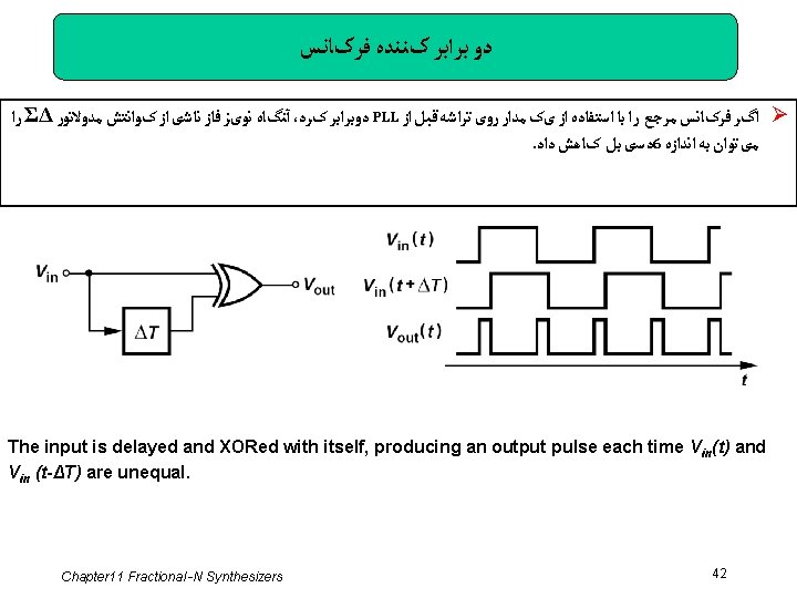
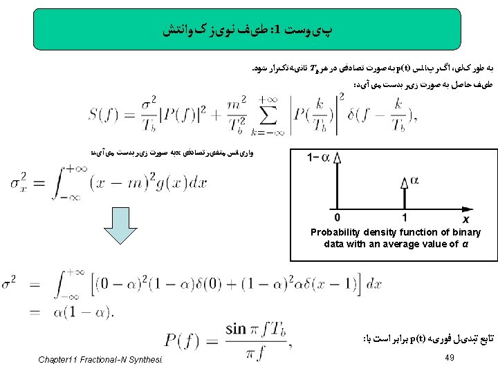
ﻧﻮیﺰ ﻓﺎﺯ ﺧﺮﻭﺟی ﻣﻮﻟﺪ ﻓﺮکﺎﻧﺴی ﺩﺭ پﻬﻨﺎی ﺑﺎﻧﺪ ﺣﻠﻘﻪ : ﺩﺍﺭیﻢ fout = (N+α)f. REF : ﺑﻪ ﺻﻮﺭﺗی ﺩیگﺮ ﺍﺯ آﻨﺠﺎ کﻪ Compute Sq(f) if b(t) consists of square pulses of width Tb that randomly repeat at a rate of 1/Tb We first determine the spectrum of b(t), Sb(f). As shown in Appendix I, Sb(f) is given by: where the second term signifies the dc content. Thus, revealing a main “lobe” between f = 0 and f = 1/Tb Chapter 11 Fractional -N Synthesizers 10
 ﺯﻣﺎﻥ ﺳیﺴﺘﻢ ﻗﺒﻠی - ﻣﺜﺎﻟی ﺍﺯ ﻧﺴﺨﻪ گﺴﺴﺘﻪ Construct a discrete-time version of")
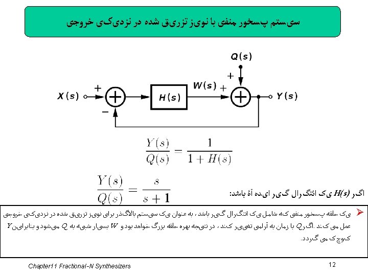
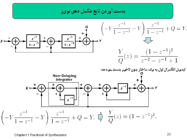
(Ⅰ) ﺯﻣﺎﻥ ﺳیﺴﺘﻢ ﻗﺒﻠی - ﻣﺜﺎﻟی ﺍﺯ ﻧﺴﺨﻪ گﺴﺴﺘﻪ Construct a discrete-time version of the system shown in the previous slide if H must operate as an integrator Solution: Discrete-time integration can be realized by delaying the signal and adding the result to itself. We observe that if, for example, A = 1, then the output continues to rise in unity increments in each clock cycle. Since the z-transform of a single-clock delay is equal to z-1, we draw the integrator as shown below and express the integrator transfer function as Chapter 11 Fractional -N Synthesizers 13
 ﺯﻣﺎﻥ ﺳیﺴﺘﻢ ﻗﺒﻠی - ﻣﺜﺎﻟی ﺍﺯ ﻧﺴﺨﻪ گﺴﺴﺘﻪ Construct a discrete-time version of")
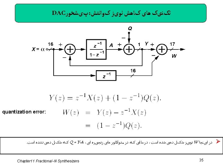
(Ⅱ) ﺯﻣﺎﻥ ﺳیﺴﺘﻢ ﻗﺒﻠی - ﻣﺜﺎﻟی ﺍﺯ ﻧﺴﺨﻪ گﺴﺴﺘﻪ Construct a discrete-time version of the system shown in the previous slide if H must operate as an integrator Thus, the discrete-time version of the system appears as shown above. Here, if Q = 0, then i. e. , the output simply tracks the input with a delay. Also, if X = 0, then This is a high-pass response (that of a differentiator) because subtracting the delayed version of a signal from the signal yields a small output if the signal does not change significantly during the delay. Chapter 11 Fractional -N Synthesizers 14

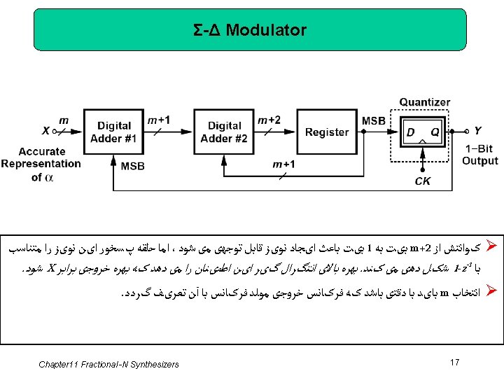
ﺑیﺘی m ﻣﺜﺎﻟی ﺍﺯ ﺳیﺴﺘﻢ ﻓیﺪﺑک ﺑﺎ یک ﻭﺭﻭﺩی Construct the system in the previous example in the digital domain with a precision (word length) of m bits. Shown here, the system incorporates an input adder (#1) (in fact a subtractor) and an integrator (“accumulator”) consisting of a digital adder (#2) and a register (delay element). The first adder receives two m-bit inputs, producing an (m + 1)-bit output. Similarly, the integrator produces an (m + 2)-bit output. Since the feedback path from Y drops the two least significant bits of the integrator output, we say it introduces quantization noise, which is modeled by an additive term, Q. In analogy with the continuous-time version, we note that the high integrator gain forces Y to be equal to X at low frequencies, i. e. , the average of Y is equal to the average of X. Chapter 11 Fractional -N Synthesizers 16

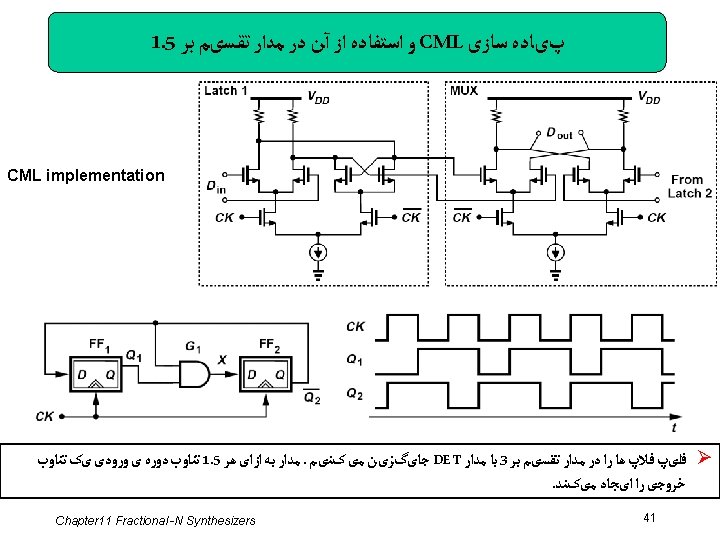
ﻣﺜﺎﻟی ﺍﺯ ﻋﻤﻞ ﺗﺮکیﺐ ﺳیگﻨﺎﻝ Construct a circuit that performs the combining operation shown previously. Solution: For 1 -bit streams, multiplication by z -1 is realized by a flipflop. The circuit thus appears as shown below: Chapter 11 Fractional -N Synthesizers 27
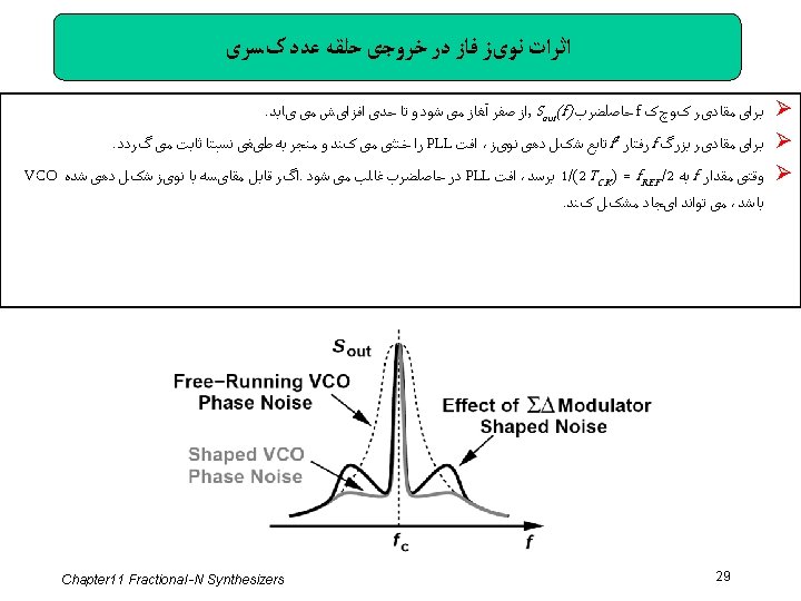
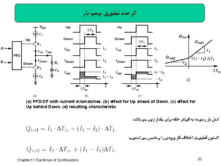

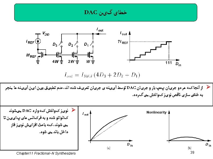
ﻣﺜﺎﻟی ﺍﺯ ﺍﺛﺮ ﻏیﺮ ﺧﻄﺴﺎﻧی ﺑﺎﻻ ﺩﺭ ﻣﻮﻟﺪ ﻓﺮکﺎﻧﺴی ﻋﺪﺩ ﺻیﺤیﺢ Does the above nonlinearity manifest itself in integer-N synthesizers? No, it does not. Recall from Chapter 9 that, in the presence of a mismatch between I 1 and I 2, an integer-N PLL locks with a static phase offset, ΔT 0, such that the net charge injected into the loop filter is zero. Now suppose the divider output phase experiences a small positive instantaneous jump (e. g. , due to the VCO phase noise). The net charge therefore becomes proportionally positive. Similarly, for a small negative instantaneous phase jump, the net charge becomes proportionally negative. The key point is that, in both cases, the charge is proportional to I 1, leading to the characteristic shown in (d). Chapter 11 Fractional -N Synthesizers 31

 as")
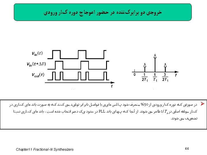
ﻣﺜﺎﻟی ﺍﺯ ﺳﺮی ﻓﻮﺭیﻪ ی ﺧﺮﻭﺟی ﺩﻭ ﺑﺮﺍﺑﺮکﻨﻨﺪﻩ If we consider Vout(t) as the sum of the two half-rate waveforms, determine the Fourier series of Vout(t). The Fourier series of V 1(t) can be written as where ω0 = 2π/(2 T 1). The second waveform, V 2(t), is obtained by shifting V 1 by T 1. Thus, the first harmonic is shifted by ω0 T 1 = π, the second by 2ω0 T 1 = 2π, etc. It follows that Adding V 1(t) and V 2(t), we note that all odd harmonics of ω0 vanish, yielding a waveform with a fundamental frequency of 2ω0 Chapter 11 Fractional -N Synthesizers 43

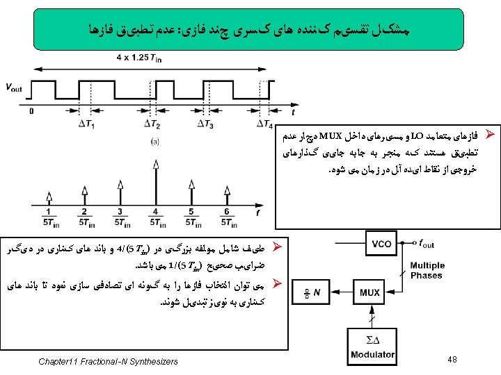
ﺗﻘﺴیﻢ ﻓﺮکﺎﻧﺴی چﻨﺪ ﻓﺎﺯی It is possible to create a fractional divide ratio by means of a multi-phase VCO and a multiplexer. Suppose a VCO generates M output phases with a minimum spacing of 2π/M, and the MUX selects one phase each time, producing an output given by where k is an integer. Now, let us assume that k varies linearly with time, sequencing through 0, 1, · · ·, M -1, M, M + 1, · · ·. Thus, k = βt, where β denotes the rate of change of k, and hence The divide ratio is therefore equal to 1 - (β/ωc)(2π/M) Chapter 11 Fractional -N Synthesizers 45

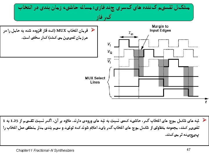
یک ﻣﺜﺎﻝ ﺍﺯ ﺗﻘﺴیﻢ ﻓﺮکﺎﻧﺴی ﻓﺎﺯﻫﺎی ﻣﺎﻟﺘی پﻠکﺲ ﺷﺪﻩ Ø This technique affords a frequency divider having a modulus of 1 and modulus of 1. 25. Since the divide ratio can be adjusted in a step of 0. 25, the quantization noise falls by 20 log 4 = 12 d. B Chapter 11 Fractional -N Synthesizers 46
 Chapter 11 Fractional -N Synthesizers 50")
References (Ⅰ) Chapter 11 Fractional -N Synthesizers 50
 Chapter 11 Fractional -N Synthesizers 51")
References (Ⅱ) Chapter 11 Fractional -N Synthesizers 51
- Slides: 51