Module4 Single phase Induction motor By Prof Arjun

Module-4 • Single phase Induction motor • By • Prof. Arjun Kumar • Asst. professor • Electrical Engineering • B. C. E. Bhagalpur

Introduction of 1 -ph. Induction Motor • A single-phase induction motor comprises a single-phase distributed winding on the stator and normal squirrel-cage rotor. • Availability of a wide variety of small-size motors of fractional kilowatt ratings. • Motors are employed in fans, refrigerators, mixers, vacuum cleaners; washing machines, other kitchen equipment, tools, small farming appliances, etc. • Behaviour of single-phase induction motor can be explained on the basis of double-field revolving theory and cross magnetic field theory. • Single phase induction motors are simple, robust, reliable and cheaper for small ratings. They are available up to 1 KW rating

CUT SECTION VIEW

Types of single phase induction motor 1. 2. 3. 4. 5. Split phase induction motor Capacitor start capacitor run induction motor Shaded pole induction motor Permanent split capacitor motor

Constructional features Fig. 4. 1 single phase I. M

Main parts of Single ph. I. M. • Single ph. I. M. having two main parts: ØStator ØRotor Stator: stator is a stationary part of induction motor. A single phase AC supply is given to the stator of single phase induction motor. In this machine stator having two windings one is main winding and other is auxiliary windings. Rotor: rotor is a rotating part of an induction motor. The rotor connects the mechanical load through the shaft. The rotor in the single-phase induction motor is of squirrel cage rotor type.

Constructional View Fig. 4. 2 constructional view of 1 -ph. I. M.

Double revolving field theory Fig. 4. 3 single phase I. M


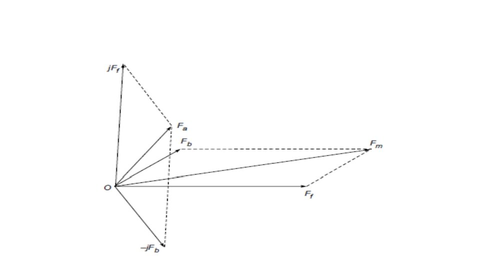
Two rotating fields rotating equivalent of a pulsating field Fig. 4. 4

Rotor slip with respect to two rotating field Fig. 4. 5


Torque slip characteristic of single winding 1 ph I. M

Equivalent circuit of single ph I. M

Split phase 1 -ph I. M.


Split phase 1 -ph I. M. •

Resistance split 1 ph I. M. •

Resistance split 1 ph I. M.

Application of Resistance split 1 ph I. M. • It has a low starting current and moderate starting torque. • It is used for easily started loads and typical applications. • fans, saws, grinders, blowers, centrifugal pumps, office equipment, washing machines etc. • available in the range of 1/20 to 1/2 k. W.

Capacitor-start Motor

Capacitor-start Motor • It uses the capacitor only for the purpose of starting. • The capacitor value isusually so chosen as to give a = 90° elect. • The starting torque is high. • capacitor need only be short-time rated

Capacitor-start Motor

Application of Capacitor-start Motor • Motor has a high starting torque and therefore is used for hard starting loads. • Typical application in compressors, conveyors, pumps, certain machine tools, refrigeration and air-conditioning equipment. • Available up to sizes as large as 6 k. W.

Two value capacitor motor

Two value capacitor motor •

Two value capacitor motor

Application of two value capacitor motor • It combines the advantages of capacitor-start and permanent-capacitor motors and is used for hard to start loads. • It gives a high power factor and efficiency under running conditions. • applications in refrigerators, compressors and stockers.

Equivalent circuit parameter •

Transformer eq. ckt of Single phase I. M • Rotor is stationary • Not showing forward and backward field rotor circuit

Rotating field equivalent ckt. of 1 -ph I. M with rotor stationary • Rotor stationary • Showing effect on equivalent ckt. by forward and backward field.

Rotating field equivalent ckt. of 1 -ph I. M with rotor running • Rotor is running • Showing effect on equivalent ckt. by forward and backward field.

No-load and blocked rotor test of 1 ph. I. M. • Aim to determine the equivalent circuit parameters of a single phase induction motor by performing the No-load and blocked rotor test. • Circuit diagram as:

No load Test •

No load test •

No load Test experimental procedure • Circuit connections are made as per the circuit diagram. • Variac (auto transformer) is set to zero output voltage position before starting the test. • Gradually increasing the voltage across the 1 - ph I. M. • Motor is freely running at no load. • Variac is varied slowly, until rated voltage is applied to motor. • Reading of ammeter , voltmeter and wattmeter is taken when reaching rated voltage across 1 - ph I. M. • Variac is brought to zero output voltage position after test. • Switch off the supply.

Blocked rotor test. •

Blocked rotor test •
- Slides: 43