
Module3 Transmission Lecture3 27400 Marc Moonen Dept E






- Slides: 50
Module-3 : Transmission Lecture-3 (27/4/00) Marc Moonen Dept. E. E. /ESAT, K. U. Leuven marc. moonen@esat. kuleuven. ac. be www. esat. kuleuven. ac. be/sista/~moonen/ Postacademic Course on Telecommunications Module-3 Transmission Lecture-3 Transmitter Design Marc Moonen K. U. Leuven/ESAT-SISTA 27/4/00 p. 1
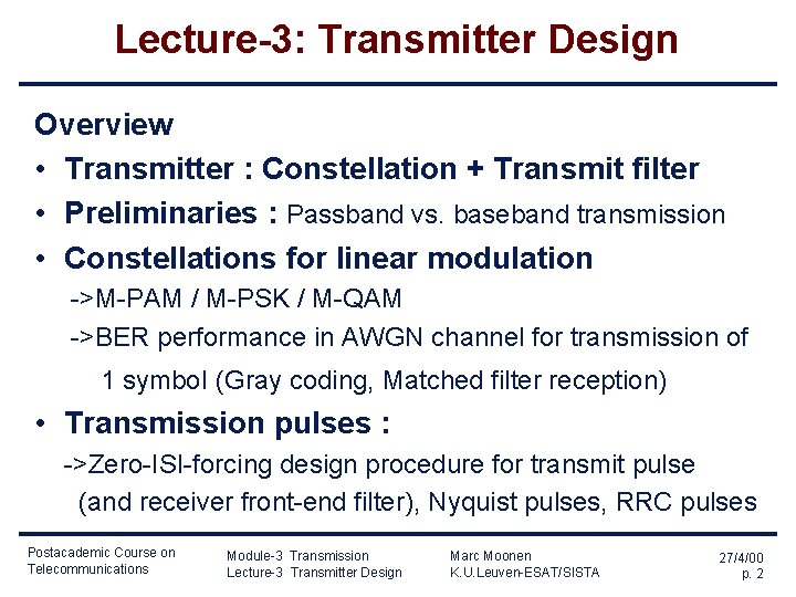
Lecture-3: Transmitter Design Overview • Transmitter : Constellation + Transmit filter • Preliminaries : Passband vs. baseband transmission • Constellations for linear modulation ->M-PAM / M-PSK / M-QAM ->BER performance in AWGN channel for transmission of 1 symbol (Gray coding, Matched filter reception) • Transmission pulses : ->Zero-ISI-forcing design procedure for transmit pulse (and receiver front-end filter), Nyquist pulses, RRC pulses Postacademic Course on Telecommunications Module-3 Transmission Lecture-3 Transmitter Design Marc Moonen K. U. Leuven-ESAT/SISTA 27/4/00 p. 2
Lecture-3: Transmitter Design Lecture partly adopted from Module T 2 `Digital Communication Principles’ M. Engels, M. Moeneclaey, G. Van Der Plas 1998 Postgraduate Course on Telecommunications Special thanks to Prof. Marc Moeneclaey Postacademic Course on Telecommunications Module-3 Transmission Lecture-3 Transmitter Design Marc Moonen K. U. Leuven-ESAT/SISTA 27/4/00 p. 3
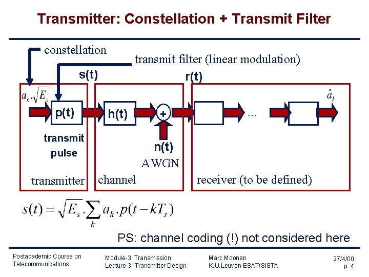
Transmitter: Constellation + Transmit Filter constellation transmit filter (linear modulation) r(t) s(t) p(t) h(t) transmit pulse transmitter + . . . n(t) AWGN channel receiver (to be defined) PS: channel coding (!) not considered here Postacademic Course on Telecommunications Module-3 Transmission Lecture-3 Transmitter Design Marc Moonen K. U. Leuven-ESAT/SISTA 27/4/00 p. 4
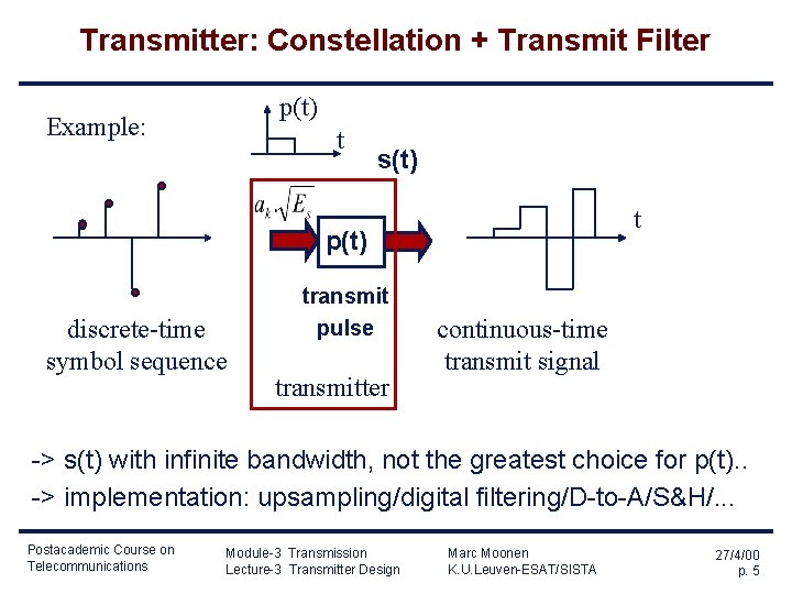
Transmitter: Constellation + Transmit Filter p(t) Example: t s(t) t p(t) discrete-time symbol sequence transmit pulse transmitter continuous-time transmit signal -> s(t) with infinite bandwidth, not the greatest choice for p(t). . -> implementation: upsampling/digital filtering/D-to-A/S&H/. . . Postacademic Course on Telecommunications Module-3 Transmission Lecture-3 Transmitter Design Marc Moonen K. U. Leuven-ESAT/SISTA 27/4/00 p. 5
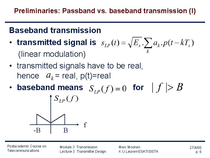
Preliminaries: Passband vs. baseband transmission (I) Baseband transmission • transmitted signal is (linear modulation) • transmitted signals have to be real, hence = real, p(t)=real • baseband means for -B Postacademic Course on Telecommunications B f Module-3 Transmission Lecture-3 Transmitter Design Marc Moonen K. U. Leuven-ESAT/SISTA 27/4/00 p. 6
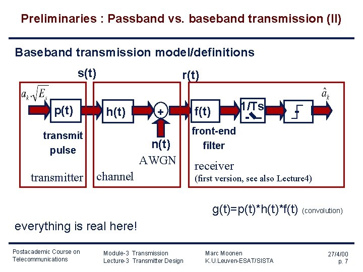
Preliminaries : Passband vs. baseband transmission (II) Baseband transmission model/definitions s(t) p(t) r(t) h(t) transmit pulse transmitter + n(t) AWGN channel 1/Ts f(t) front-end filter receiver (first version, see also Lecture 4) g(t)=p(t)*h(t)*f(t) (convolution) everything is real here! Postacademic Course on Telecommunications Module-3 Transmission Lecture-3 Transmitter Design Marc Moonen K. U. Leuven-ESAT/SISTA 27/4/00 p. 7
Preliminaries : Passband vs. baseband transmission (III) Bandpass transmission transmitted signal is modulated baseband signal `envelope’ -B B Postacademic Course on Telecommunications f Module-3 Transmission Lecture-3 Transmitter Design -fo Marc Moonen K. U. Leuven-ESAT/SISTA fo fo+B f 27/4/00 p. 8
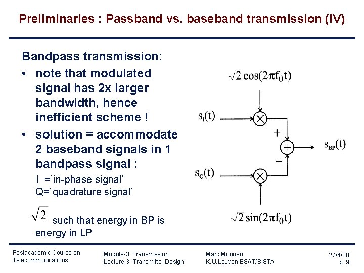
Preliminaries : Passband vs. baseband transmission (IV) Bandpass transmission: • note that modulated signal has 2 x larger bandwidth, hence inefficient scheme ! • solution = accommodate 2 baseband signals in 1 bandpass signal : I =`in-phase signal’ Q=`quadrature signal’ such that energy in BP is energy in LP Postacademic Course on Telecommunications Module-3 Transmission Lecture-3 Transmitter Design Marc Moonen K. U. Leuven-ESAT/SISTA 27/4/00 p. 9
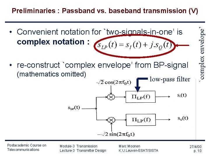
• Convenient notation for `two-signals-in-one’ is complex notation : • re-construct `complex envelope’ from BP-signal (mathematics omitted) Postacademic Course on Telecommunications Module-3 Transmission Lecture-3 Transmitter Design low-pass filter Marc Moonen K. U. Leuven-ESAT/SISTA `complex envelope’ Preliminaries : Passband vs. baseband transmission (V) 27/4/00 p. 10
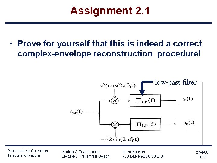
Assignment 2. 1 • Prove for yourself that this is indeed a correct complex-envelope reconstruction procedure! low-pass filter Postacademic Course on Telecommunications Module-3 Transmission Lecture-3 Transmitter Design Marc Moonen K. U. Leuven-ESAT/SISTA 27/4/00 p. 11
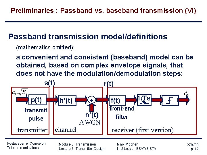
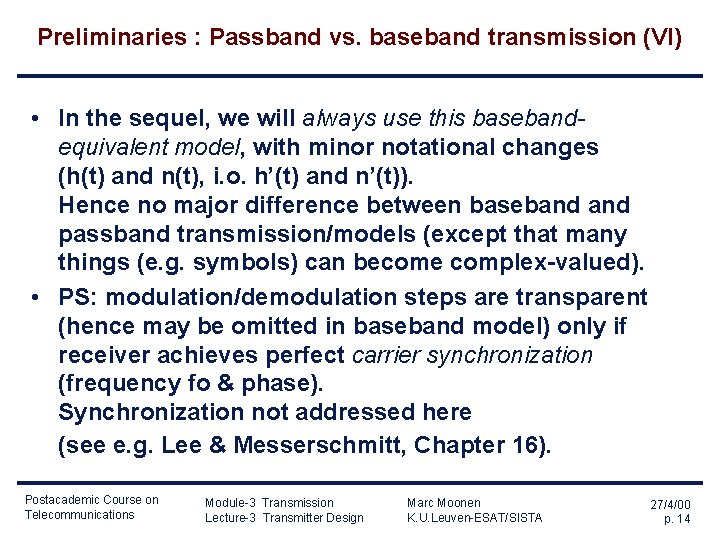
Preliminaries : Passband vs. baseband transmission (VI) Passband transmission model/definitions (mathematics omitted): a convenient and consistent (baseband) model can be obtained, based on complex envelope signals, that does not have the modulation/demodulation steps: s(t) r(t) p(t) h’(t) transmit pulse transmitter Postacademic Course on Telecommunications channel + n’(t) AWGN Module-3 Transmission Lecture-3 Transmitter Design f(t) 1/Ts front-end filter receiver (first version) Marc Moonen K. U. Leuven-ESAT/SISTA 27/4/00 p. 12
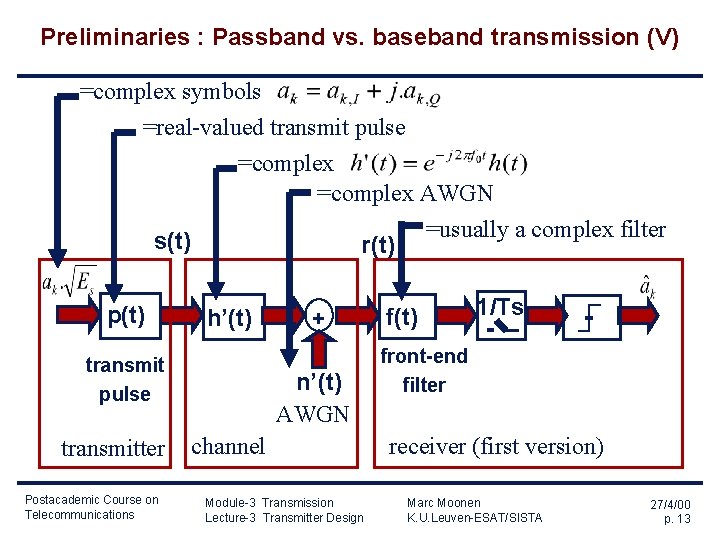
Preliminaries : Passband vs. baseband transmission (V) =complex symbols =real-valued transmit pulse s(t) p(t) =complex AWGN =usually a complex filter r(t) h’(t) transmit pulse transmitter Postacademic Course on Telecommunications + n’(t) AWGN channel Module-3 Transmission Lecture-3 Transmitter Design f(t) 1/Ts front-end filter receiver (first version) Marc Moonen K. U. Leuven-ESAT/SISTA 27/4/00 p. 13
Preliminaries : Passband vs. baseband transmission (VI) • In the sequel, we will always use this basebandequivalent model, with minor notational changes (h(t) and n(t), i. o. h’(t) and n’(t)). Hence no major difference between baseband passband transmission/models (except that many things (e. g. symbols) can become complex-valued). • PS: modulation/demodulation steps are transparent (hence may be omitted in baseband model) only if receiver achieves perfect carrier synchronization (frequency fo & phase). Synchronization not addressed here (see e. g. Lee & Messerschmitt, Chapter 16). Postacademic Course on Telecommunications Module-3 Transmission Lecture-3 Transmitter Design Marc Moonen K. U. Leuven-ESAT/SISTA 27/4/00 p. 14
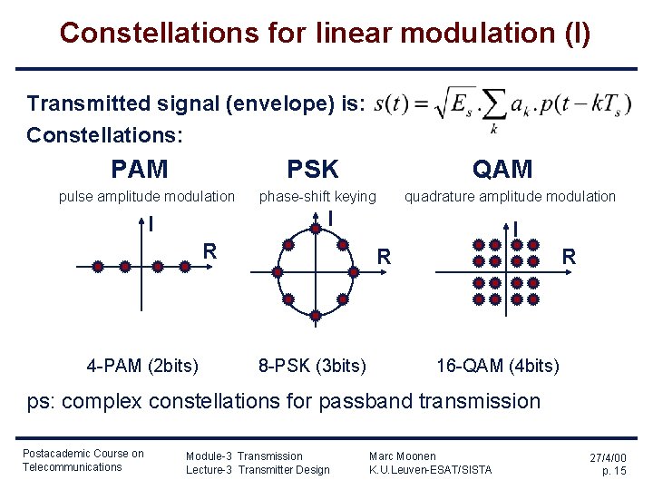
Constellations for linear modulation (I) Transmitted signal (envelope) is: Constellations: PAM PSK pulse amplitude modulation QAM phase-shift keying quadrature amplitude modulation I I R 4 -PAM (2 bits) I R 8 -PSK (3 bits) R 16 -QAM (4 bits) ps: complex constellations for passband transmission Postacademic Course on Telecommunications Module-3 Transmission Lecture-3 Transmitter Design Marc Moonen K. U. Leuven-ESAT/SISTA 27/4/00 p. 15
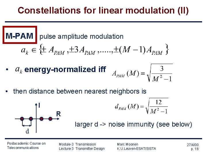
Constellations for linear modulation (II) M-PAM pulse amplitude modulation • energy-normalized iff • then distance between nearest neighbors is I R d Postacademic Course on Telecommunications larger d -> noise immunity (see below) Module-3 Transmission Lecture-3 Transmitter Design Marc Moonen K. U. Leuven-ESAT/SISTA 27/4/00 p. 16
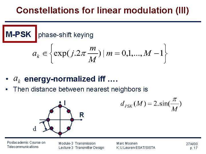
Constellations for linear modulation (III) M-PSK phase-shift keying • energy-normalized iff …. • Then distance between nearest neighbors is I R d Postacademic Course on Telecommunications Module-3 Transmission Lecture-3 Transmitter Design Marc Moonen K. U. Leuven-ESAT/SISTA 27/4/00 p. 17
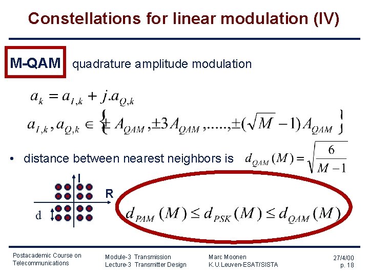
Constellations for linear modulation (IV) M-QAM quadrature amplitude modulation • distance between nearest neighbors is I R d Postacademic Course on Telecommunications Module-3 Transmission Lecture-3 Transmitter Design Marc Moonen K. U. Leuven-ESAT/SISTA 27/4/00 p. 18
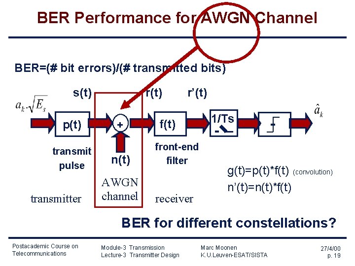
BER Performance for AWGN Channel BER=(# bit errors)/(# transmitted bits) s(t) p(t) transmit pulse transmitter r(t) + r’(t) f(t) n(t) front-end filter AWGN channel receiver 1/Ts g(t)=p(t)*f(t) (convolution) n’(t)=n(t)*f(t) BER for different constellations? Postacademic Course on Telecommunications Module-3 Transmission Lecture-3 Transmitter Design Marc Moonen K. U. Leuven-ESAT/SISTA 27/4/00 p. 19
BER Performance for AWGN Channel definitions: - transmitted signal - received signal (at front-end filter) - received signal (at sampler) g(t) =p(t)*f(t) = transmitted pulse p(t) filtered by front-end filter n’(t) =n(t)*f(t) = AWGN filtered by front-end filter Postacademic Course on Telecommunications Module-3 Transmission Lecture-3 Transmitter Design Marc Moonen K. U. Leuven-ESAT/SISTA 27/4/00 p. 20
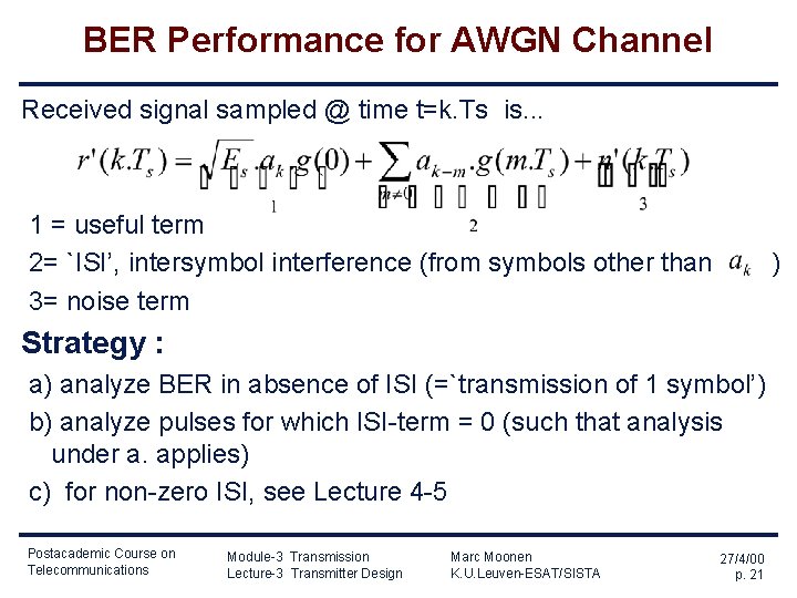
BER Performance for AWGN Channel Received signal sampled @ time t=k. Ts is. . . 1 = useful term 2= `ISI’, intersymbol interference (from symbols other than 3= noise term ) Strategy : a) analyze BER in absence of ISI (=`transmission of 1 symbol’) b) analyze pulses for which ISI-term = 0 (such that analysis under a. applies) c) for non-zero ISI, see Lecture 4 -5 Postacademic Course on Telecommunications Module-3 Transmission Lecture-3 Transmitter Design Marc Moonen K. U. Leuven-ESAT/SISTA 27/4/00 p. 21
Transmission of 1 symbol over AWGN channel (I) transmit 1 symbol at time 0. Ts. . . p(t) transmit pulse f(t) + n(t) . . . take 1 sample at time 0. Ts 1/Ts front-end filter AWGN channel BER for different constellations? Postacademic Course on Telecommunications Module-3 Transmission Lecture-3 Transmitter Design Marc Moonen K. U. Leuven-ESAT/SISTA 27/4/00 p. 22
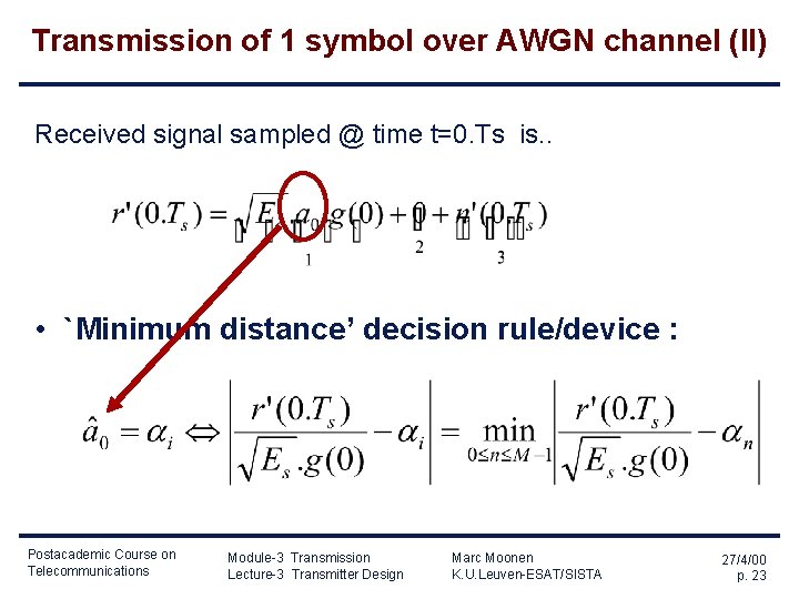
Transmission of 1 symbol over AWGN channel (II) Received signal sampled @ time t=0. Ts is. . • `Minimum distance’ decision rule/device : Postacademic Course on Telecommunications Module-3 Transmission Lecture-3 Transmitter Design Marc Moonen K. U. Leuven-ESAT/SISTA 27/4/00 p. 23
Transmission of 1 symbol over AWGN channel (III) `Minimum distance’ decision rule : Example : decision regions for 16 -QAM I R Postacademic Course on Telecommunications Module-3 Transmission Lecture-3 Transmitter Design Marc Moonen K. U. Leuven-ESAT/SISTA 27/4/00 p. 24
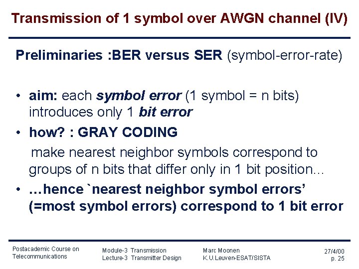
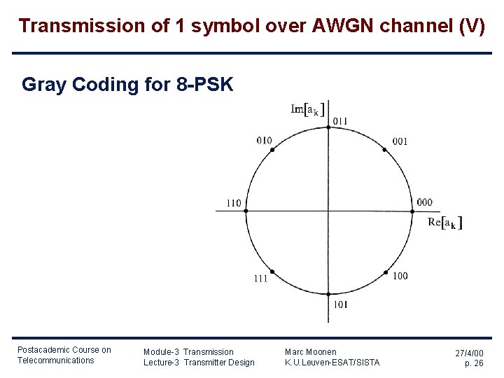
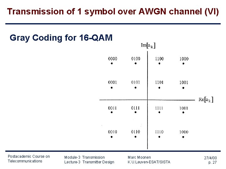
Transmission of 1 symbol over AWGN channel (IV) Preliminaries : BER versus SER (symbol-error-rate) • aim: each symbol error (1 symbol = n bits) introduces only 1 bit error • how? : GRAY CODING make nearest neighbor symbols correspond to groups of n bits that differ only in 1 bit position… • …hence `nearest neighbor symbol errors’ (=most symbol errors) correspond to 1 bit error Postacademic Course on Telecommunications Module-3 Transmission Lecture-3 Transmitter Design Marc Moonen K. U. Leuven-ESAT/SISTA 27/4/00 p. 25
Transmission of 1 symbol over AWGN channel (V) Gray Coding for 8 -PSK Postacademic Course on Telecommunications Module-3 Transmission Lecture-3 Transmitter Design Marc Moonen K. U. Leuven-ESAT/SISTA 27/4/00 p. 26
Transmission of 1 symbol over AWGN channel (VI) Gray Coding for 16 -QAM Postacademic Course on Telecommunications Module-3 Transmission Lecture-3 Transmitter Design Marc Moonen K. U. Leuven-ESAT/SISTA 27/4/00 p. 27
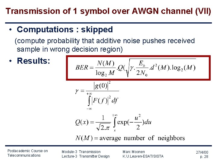
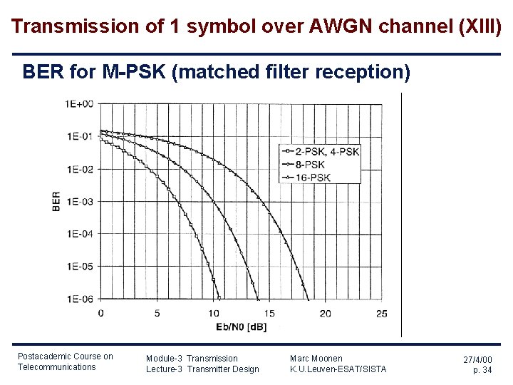
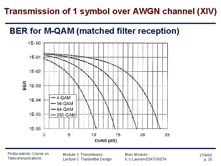
Transmission of 1 symbol over AWGN channel (VII) • Computations : skipped (compute probability that additive noise pushes received sample in wrong decision region) • Results: Postacademic Course on Telecommunications Module-3 Transmission Lecture-3 Transmitter Design Marc Moonen K. U. Leuven-ESAT/SISTA 27/4/00 p. 28
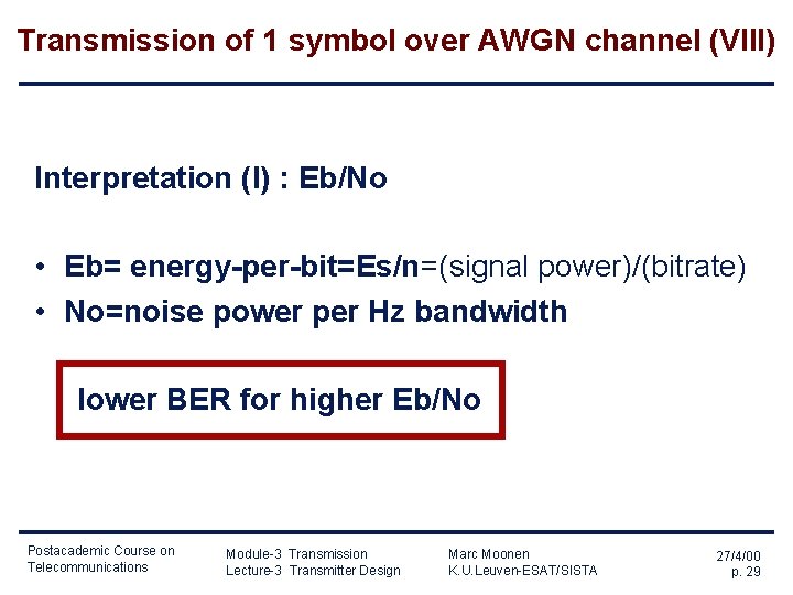
Transmission of 1 symbol over AWGN channel (VIII) Interpretation (I) : Eb/No • Eb= energy-per-bit=Es/n=(signal power)/(bitrate) • No=noise power per Hz bandwidth lower BER for higher Eb/No Postacademic Course on Telecommunications Module-3 Transmission Lecture-3 Transmitter Design Marc Moonen K. U. Leuven-ESAT/SISTA 27/4/00 p. 29
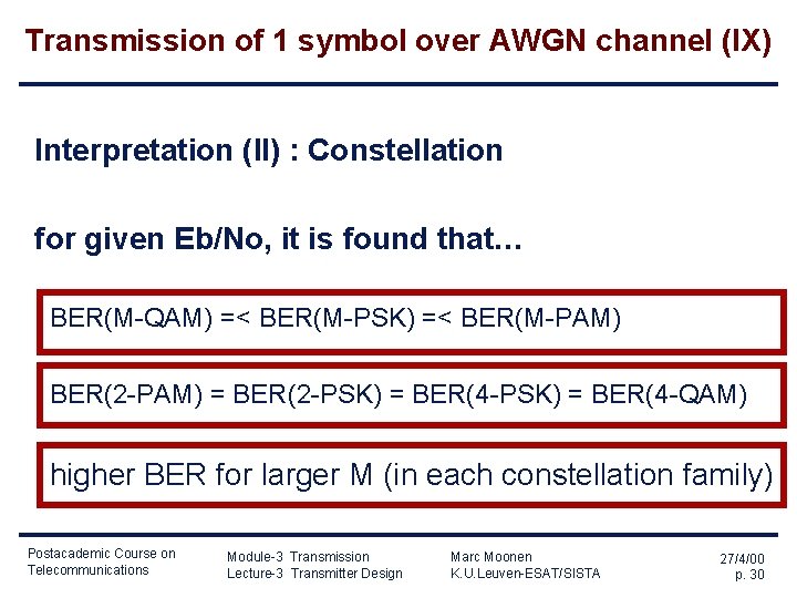
Transmission of 1 symbol over AWGN channel (IX) Interpretation (II) : Constellation for given Eb/No, it is found that… BER(M-QAM) =< BER(M-PSK) =< BER(M-PAM) BER(2 -PAM) = BER(2 -PSK) = BER(4 -QAM) higher BER for larger M (in each constellation family) Postacademic Course on Telecommunications Module-3 Transmission Lecture-3 Transmitter Design Marc Moonen K. U. Leuven-ESAT/SISTA 27/4/00 p. 30
Transmission of 1 symbol over AWGN channel (X) Interpretation (III): front-end filter f(t) It is proven that and that is obtained only when this is known as the `matched filter receiver’ (see also Lecture-4) Postacademic Course on Telecommunications Module-3 Transmission Lecture-3 Transmitter Design Marc Moonen K. U. Leuven-ESAT/SISTA 27/4/00 p. 31
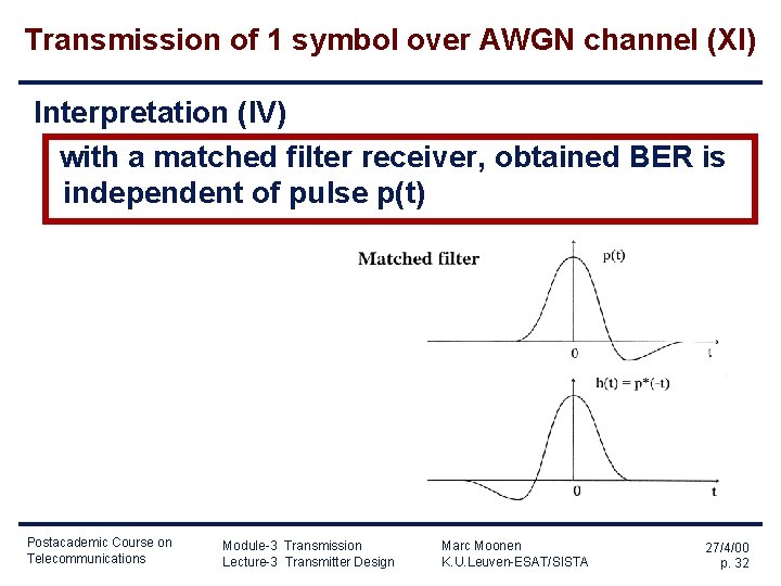
Transmission of 1 symbol over AWGN channel (XI) Interpretation (IV) with a matched filter receiver, obtained BER is independent of pulse p(t) Postacademic Course on Telecommunications Module-3 Transmission Lecture-3 Transmitter Design Marc Moonen K. U. Leuven-ESAT/SISTA 27/4/00 p. 32
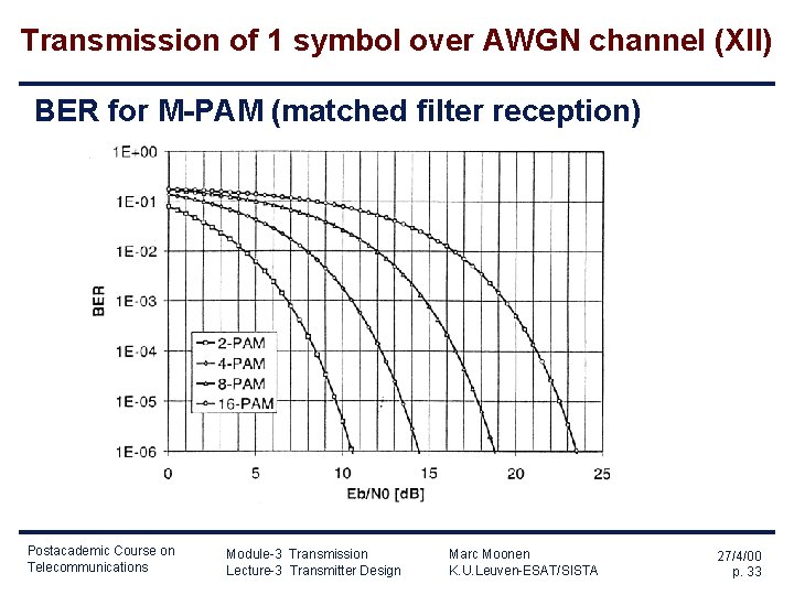
Transmission of 1 symbol over AWGN channel (XII) BER for M-PAM (matched filter reception) Postacademic Course on Telecommunications Module-3 Transmission Lecture-3 Transmitter Design Marc Moonen K. U. Leuven-ESAT/SISTA 27/4/00 p. 33
Transmission of 1 symbol over AWGN channel (XIII) BER for M-PSK (matched filter reception) Postacademic Course on Telecommunications Module-3 Transmission Lecture-3 Transmitter Design Marc Moonen K. U. Leuven-ESAT/SISTA 27/4/00 p. 34
Transmission of 1 symbol over AWGN channel (XIV) BER for M-QAM (matched filter reception) Postacademic Course on Telecommunications Module-3 Transmission Lecture-3 Transmitter Design Marc Moonen K. U. Leuven-ESAT/SISTA 27/4/00 p. 35
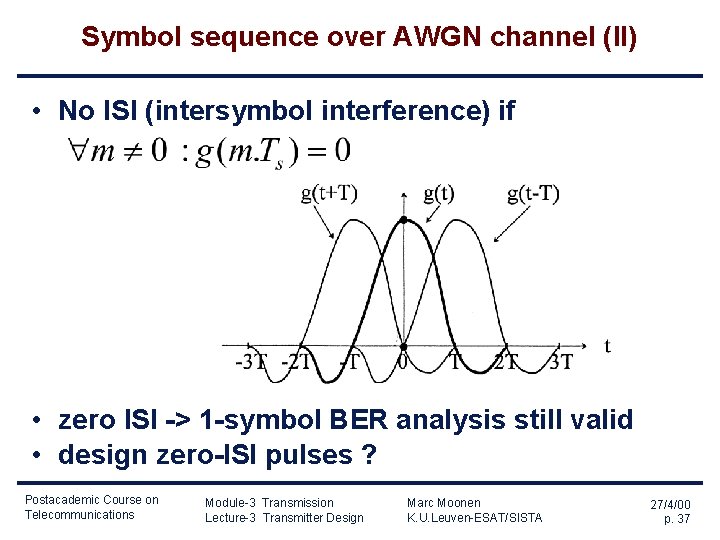
Symbol sequence over AWGN channel (I) • ISI (intersymbol interference) results if g(t)=p(t)*f(t) • ISI results in increased BER Postacademic Course on Telecommunications Module-3 Transmission Lecture-3 Transmitter Design Marc Moonen K. U. Leuven-ESAT/SISTA 27/4/00 p. 36
Symbol sequence over AWGN channel (II) • No ISI (intersymbol interference) if • zero ISI -> 1 -symbol BER analysis still valid • design zero-ISI pulses ? Postacademic Course on Telecommunications Module-3 Transmission Lecture-3 Transmitter Design Marc Moonen K. U. Leuven-ESAT/SISTA 27/4/00 p. 37
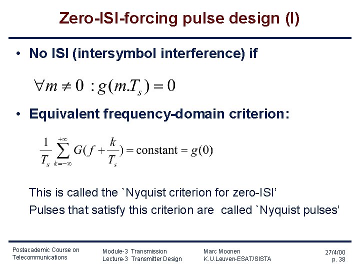
Zero-ISI-forcing pulse design (I) • No ISI (intersymbol interference) if • Equivalent frequency-domain criterion: This is called the `Nyquist criterion for zero-ISI’ Pulses that satisfy this criterion are called `Nyquist pulses’ Postacademic Course on Telecommunications Module-3 Transmission Lecture-3 Transmitter Design Marc Moonen K. U. Leuven-ESAT/SISTA 27/4/00 p. 38
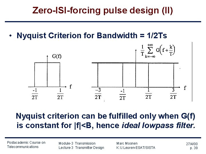
Zero-ISI-forcing pulse design (II) • Nyquist Criterion for Bandwidth = 1/2 Ts Nyquist criterion can be fulfilled only when G(f) is constant for |f|<B, hence ideal lowpass filter. Postacademic Course on Telecommunications Module-3 Transmission Lecture-3 Transmitter Design Marc Moonen K. U. Leuven-ESAT/SISTA 27/4/00 p. 39
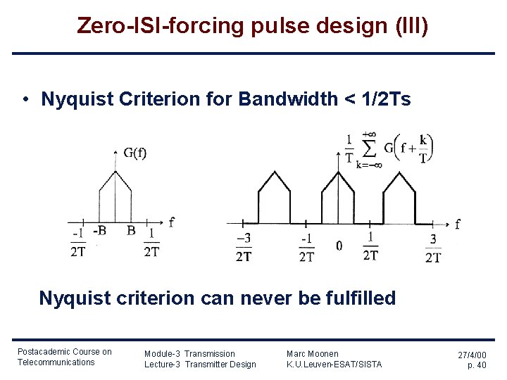
Zero-ISI-forcing pulse design (III) • Nyquist Criterion for Bandwidth < 1/2 Ts Nyquist criterion can never be fulfilled Postacademic Course on Telecommunications Module-3 Transmission Lecture-3 Transmitter Design Marc Moonen K. U. Leuven-ESAT/SISTA 27/4/00 p. 40
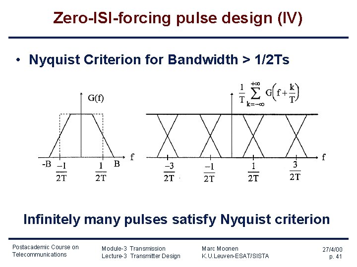
Zero-ISI-forcing pulse design (IV) • Nyquist Criterion for Bandwidth > 1/2 Ts Infinitely many pulses satisfy Nyquist criterion Postacademic Course on Telecommunications Module-3 Transmission Lecture-3 Transmitter Design Marc Moonen K. U. Leuven-ESAT/SISTA 27/4/00 p. 41
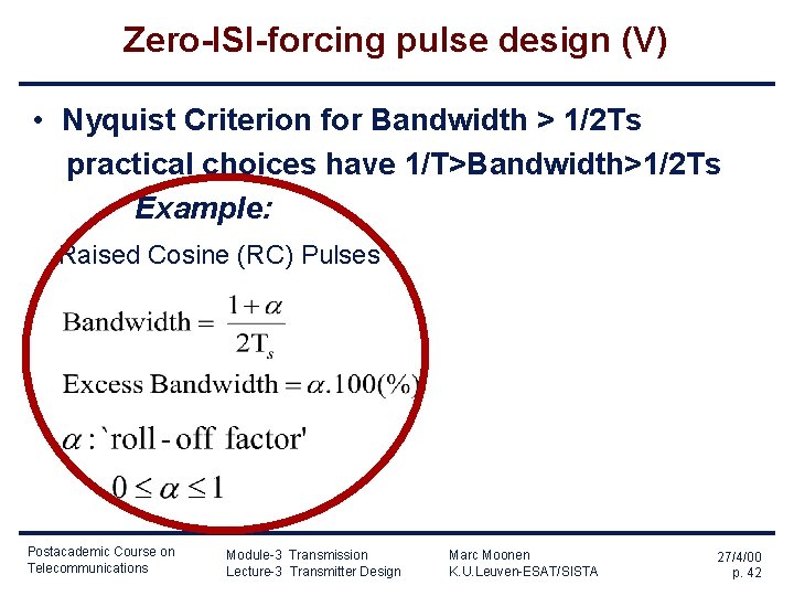
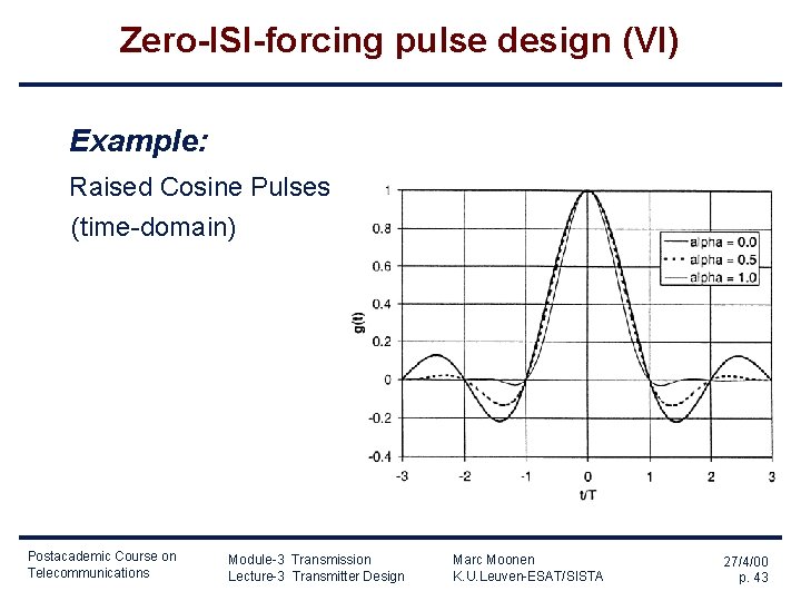
Zero-ISI-forcing pulse design (V) • Nyquist Criterion for Bandwidth > 1/2 Ts practical choices have 1/T>Bandwidth>1/2 Ts Example: Raised Cosine (RC) Pulses Postacademic Course on Telecommunications Module-3 Transmission Lecture-3 Transmitter Design Marc Moonen K. U. Leuven-ESAT/SISTA 27/4/00 p. 42
Zero-ISI-forcing pulse design (VI) Example: Raised Cosine Pulses (time-domain) Postacademic Course on Telecommunications Module-3 Transmission Lecture-3 Transmitter Design Marc Moonen K. U. Leuven-ESAT/SISTA 27/4/00 p. 43
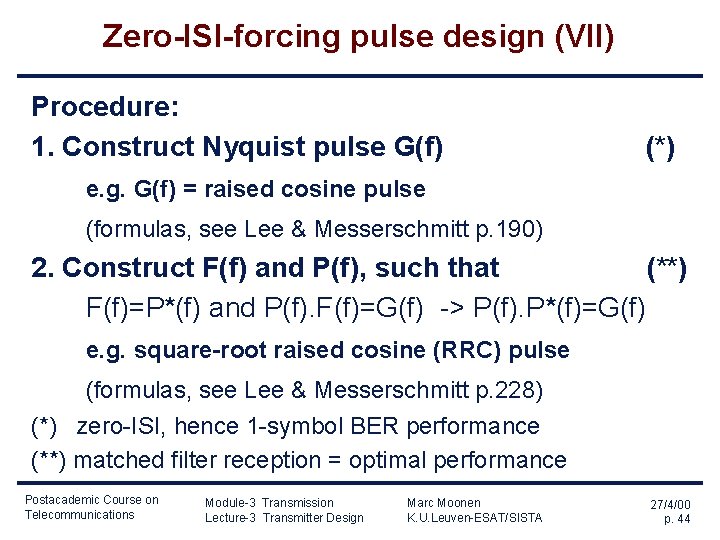
Zero-ISI-forcing pulse design (VII) Procedure: 1. Construct Nyquist pulse G(f) (*) e. g. G(f) = raised cosine pulse (formulas, see Lee & Messerschmitt p. 190) 2. Construct F(f) and P(f), such that (**) F(f)=P*(f) and P(f). F(f)=G(f) -> P(f). P*(f)=G(f) e. g. square-root raised cosine (RRC) pulse (formulas, see Lee & Messerschmitt p. 228) (*) zero-ISI, hence 1 -symbol BER performance (**) matched filter reception = optimal performance Postacademic Course on Telecommunications Module-3 Transmission Lecture-3 Transmitter Design Marc Moonen K. U. Leuven-ESAT/SISTA 27/4/00 p. 44
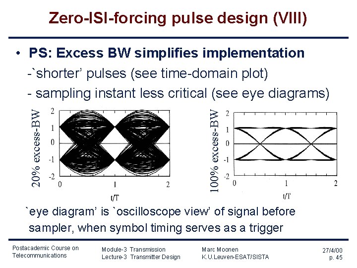
Zero-ISI-forcing pulse design (VIII) 100% excess-BW 20% excess-BW • PS: Excess BW simplifies implementation -`shorter’ pulses (see time-domain plot) - sampling instant less critical (see eye diagrams) `eye diagram’ is `oscilloscope view’ of signal before sampler, when symbol timing serves as a trigger Postacademic Course on Telecommunications Module-3 Transmission Lecture-3 Transmitter Design Marc Moonen K. U. Leuven-ESAT/SISTA 27/4/00 p. 45
Zero-ISI-forcing pulse design (IX) • PPS: From the eye diagrams, it is seen that selecting a proper sampling instant is crucial (for having zero-ISI) ->requires accurate clock synchronization, a. k. a. `timing recovery’, at the receiver (clock rate & phase) ->`timing recovery’ not addressed here see e. g. Lee & Messerschmitt, Chapter 17 Postacademic Course on Telecommunications Module-3 Transmission Lecture-3 Transmitter Design Marc Moonen K. U. Leuven-ESAT/SISTA 27/4/00 p. 46
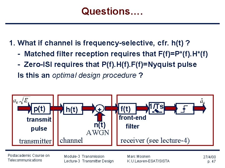
Questions…. 1. What if channel is frequency-selective, cfr. h(t) ? - Matched filter reception requires that F(f)=P*(f). H*(f) - Zero-ISI requires that P(f). H(f). F(f)=Nyquist pulse Is this an optimal design procedure ? p(t) h(t) transmit pulse transmitter Postacademic Course on Telecommunications channel + n(t) AWGN Module-3 Transmission Lecture-3 Transmitter Design f(t) 1/Ts front-end filter receiver (see lecture-4) Marc Moonen K. U. Leuven-ESAT/SISTA 27/4/00 p. 47
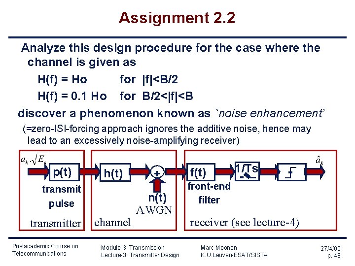
Assignment 2. 2 Analyze this design procedure for the case where the channel is given as H(f) = Ho for |f|<B/2 H(f) = 0. 1 Ho for B/2<|f|<B discover a phenomenon known as `noise enhancement’ (=zero-ISI-forcing approach ignores the additive noise, hence may lead to an excessively noise-amplifying receiver) p(t) h(t) transmit pulse transmitter Postacademic Course on Telecommunications channel + n(t) AWGN Module-3 Transmission Lecture-3 Transmitter Design f(t) 1/Ts front-end filter receiver (see lecture-4) Marc Moonen K. U. Leuven-ESAT/SISTA 27/4/00 p. 48
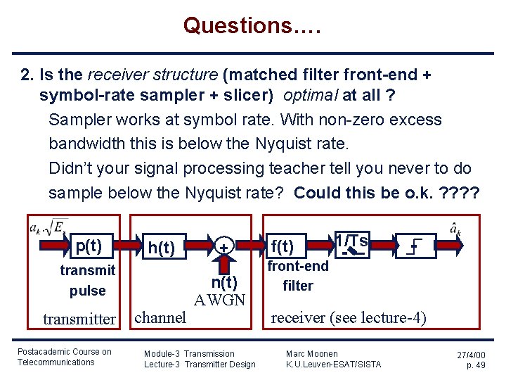
Questions…. 2. Is the receiver structure (matched filter front-end + symbol-rate sampler + slicer) optimal at all ? Sampler works at symbol rate. With non-zero excess bandwidth this is below the Nyquist rate. Didn’t your signal processing teacher tell you never to do sample below the Nyquist rate? Could this be o. k. ? ? p(t) h(t) transmit pulse transmitter Postacademic Course on Telecommunications channel + n(t) AWGN Module-3 Transmission Lecture-3 Transmitter Design f(t) 1/Ts front-end filter receiver (see lecture-4) Marc Moonen K. U. Leuven-ESAT/SISTA 27/4/00 p. 49
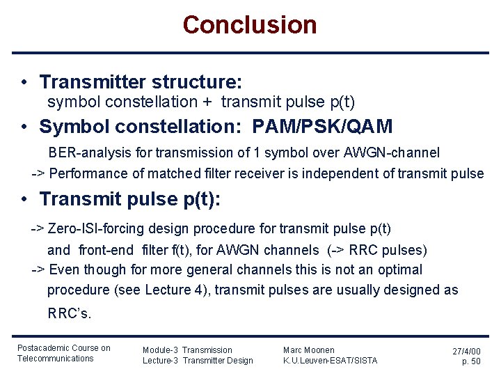
Conclusion • Transmitter structure: symbol constellation + transmit pulse p(t) • Symbol constellation: PAM/PSK/QAM BER-analysis for transmission of 1 symbol over AWGN-channel -> Performance of matched filter receiver is independent of transmit pulse • Transmit pulse p(t): -> Zero-ISI-forcing design procedure for transmit pulse p(t) and front-end filter f(t), for AWGN channels (-> RRC pulses) -> Even though for more general channels this is not an optimal procedure (see Lecture 4), transmit pulses are usually designed as RRC’s. Postacademic Course on Telecommunications Module-3 Transmission Lecture-3 Transmitter Design Marc Moonen K. U. Leuven-ESAT/SISTA 27/4/00 p. 50