Module III Processor Organization and Architecture Microprogrammed Control


- Slides: 27
Module III Processor Organization and Architecture
Micro-programmed Control Unit
Wilkes Control • 1951 • To store microprogram, it should contain rapid access storage device and hence a diode matrix is used.
Wilkes Control
Wilkes Control • For any microoperation, we need to configure the diodes in the matrix. • During a machine cycle, one row of matrix is activated with a pulse. This generates signals at those points where diode is present
Wilkes Control • First part generates control signals • Second part generates the next address of the row to be pulsed • Each row is one microinstruction • Layout of matrix is control memory
Wilkes Control • At the beginning of cycle, Register 1 contains the address of the row to be pulsed • Register 1 is fed to decoder which when activated by clock pulse, activates one row • The first part generate control signals & second part generate next address which is fed into Register. II
Wilkes Control • Register II is gated to Register I by a clock pulse • Application of pulses alternatively to decoder and gate connecting Register I and II causes a predetermined sequence of microinstrucitons to be executed
Wilkes Control • It is similar to Horizontal, the major differences are – CAR could be incremented by 1 in HM, but next address is contained in Wilkes Scheme – To permit branching , a row must contain two parts controlled by a conditional signal in Wilkes.
Adv. Of Micro-programmed CU Simpler to design Cheaper Less Prone to Error Less logic required for sequencing and decoding • Easy to implement • •
Disadv. Of Micro-programmed CU • Slower in performance Application • Hardwired : mainly RISC processors • Microprogrammed : CISC processors
Microinstruction Sequencing • Based on current microinstruction, conditional flags and contents of IR, next control memory address must be generated. • Based on the format of address information in the microinstruction, it is classified into 3 categories: – Two Address Fields – Single Address Field – Variable Format
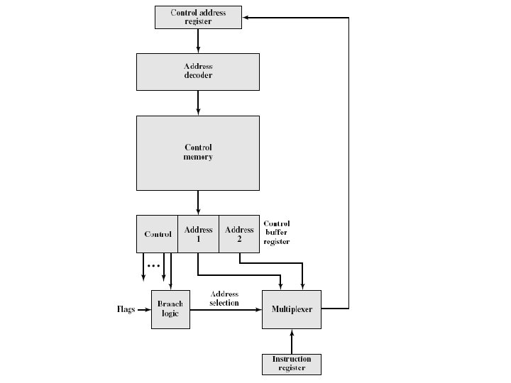
Two Address Fields
Two Address Fields • It is the simplest approach • It provides two address fields in microinstruction
Two Address Fields • Address-selection signals are provided by branch logic module (It has inputs of control unit flags and control bits from microinstruction)
Two Address Fields • Multiplexer has inputs of both address fields and instruction register. • Based on addressselection input, multiplexer transmits either opcode or one of two addresses to CAR. • CAR produce the next microinstruction address
Two Address Fields • ADV: Simple • DISADV: more bits required in microinstruction
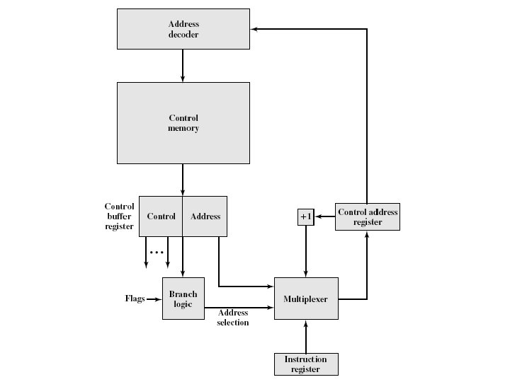
Single Address Field
Single Address Field • With this approach, the options for next address are as follows: • Address field • Instruction Register code • Next sequential address
Single Address Field • Address-selection input determine which option is selected. • Adv: reduces the number of address fields to one. • Disadv: Address field is not used often which cause inefficiency in the microinstruction coding scheme.
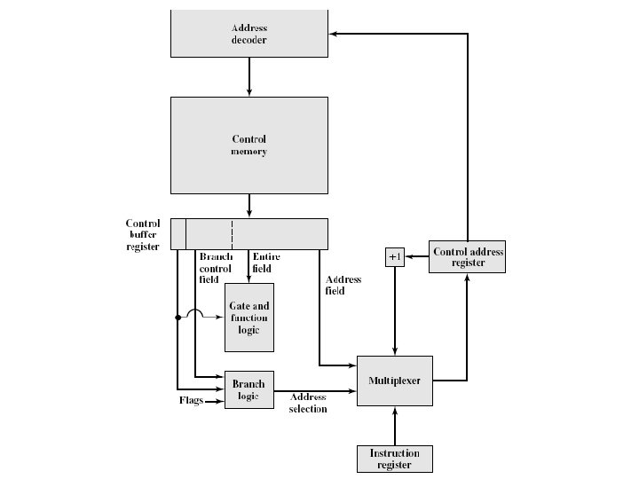
Variable Format
Variable Format • Provide for two entirely different microinstruction formats and one bit designates which format is being used. • In one format, the remaining bits activate control signals. • In other format, some bits drive branch logic module and remaining bits provide the address.
Variable Format • With first format, the next address is either sequential address or address derived from IR. • With second format, either a conditional or unconditional branch is specified.
Variable Format • Disadvantage: one entire cycle is consumed with each branch microinstruction. • With other approaches, address generation occurs as part of the same cycle.