Module 5 Functions and protocols of surveillance systems


 Coding A communications net is a group")


, pulse code")
 voice information is")
 and limiting are employed in processing the received signals to")
 coding was devised for use")


. When")

- Slides: 35
Module 5. Functions and protocols of surveillance systems Topic 5. 4. Basics of discrete address systems Lecture 5. 4. 1. Discrete address systems
RANDOM ACCESS DISCRETE ADDRESS COMMUNICATIONS SYSTEMS
Description of RADA (Random Access Discrete Address) Coding A communications net is a group of fixed or mobile individuals, within line of sight range, equipped with radio transceivers. Each net member can communicate directly to each other net member, without using intervening switching apparatus, by transmitting a radio signal which is properly addressed or coded. A common frequency band, or channel, is utilized for these transmissions.
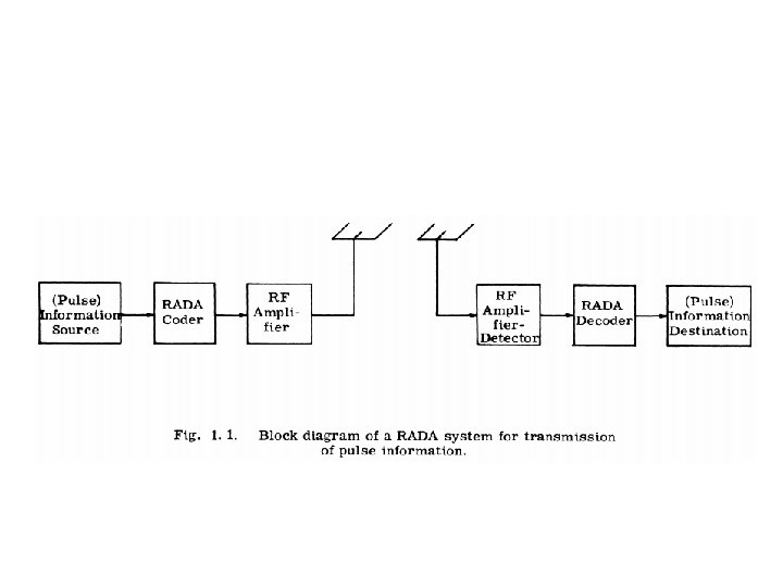
This lecture is concerned with the performance characteristics of a communications net in which a particular type of (transmission) coding, referred to as RADA coding, is used throughout. The block diagram of a typical system for use with pulse information is shown in Fig. 1 1.
When analog information is transmitted, it must first be source encoded by using some form of pulse modulation. Source encoding will be referred to herein as "modulating", permitting its clear distinction from the subsequent (RADA) transmission "coding. “ In Fig. 1. 1 RADA encoding of a signal for multiplex transmission over a wireless channel is illustrated. The same techniques may be used in a wire channel.
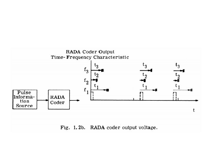
When applying the RADA principle, all information signals are first converted to a pulse signal form. Each "information pulse" is then coded into a group of pulses (a "time frequency code frame, " or "frame") which is "matched" to the receiver addressed. The coding scheme is chosen so that the RADA decoder in a particular receiver produces an output "message" pulse when a properly addressed frame is received, and (ideally) produces no output pulse when an improperly addressed frame is received.
Mutual interference among transceivers produces "error pulses" at the output of the RADA decoder because the frames from several transmitters can combine randomly to produce frames which are coded for a particular receiver, even though the frames of the individual trans mitters are not so coded.
RADA coding can be used with delta modulation, pulse position modulation (PPM), pulse code modulation (PCM) (in which case the re ceiver must be time synchronized with the transmitter), and with other types of pulse modulation.
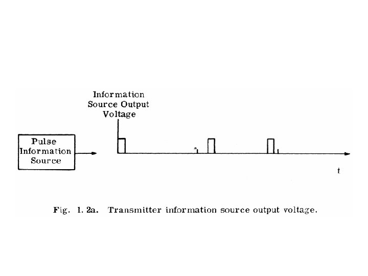
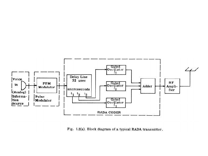
A representative implementation of a RADA system for trans mitting (analog) voice information is shown in Fig. 1. 3. A voice signal produces the information train of position modulated pulses shown in Fig. 1. 2(a) at the transmitter modulator output. Each information pulse is addressed in the RADA coder in the manner described above.
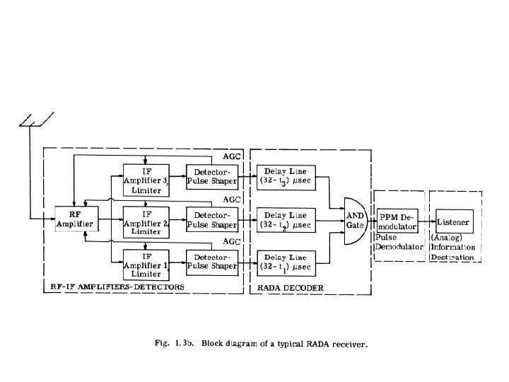
Automatic gain control (AGC) and limiting are employed in processing the received signals to accommodate the wide range of the amplitude levels of these signals (Section 1. 4. 5). Thus, the RADA coder encodes an information bearing pulse train for multiplex transmission over the channel; the RADA decoder recovers the information bearing pulse train. The use of a common frequency band by the RADA transmitters means that there is mutual interference among net users. The interference results in spurious, or error, pulses at the output of the AND gate of the receiver decoder. As discussed in Section 1. 4 3, the effect of these error pulses on the receiver output depends upon the type of demodulation employed.
Applications of RADA Coding RADA (random access discrete address) coding was devised for use in a radio pulse communication system to provide net communications characterized by a large number of net user addresses, immediate, non synchronous user access to the channel (random access), and relatively efficient use of bandwidth when the net communications system use factor is small. RADA coding principles are applicable to various modes of communication including: multiplexed signals in wire communications systems, multiplexed signals through active and passive earth satellite repeaters, multiplexed transmissions from air to air and ground to ground, as well as multiplexed communications between air and ground.
It is worthwhile to compare multiplexing using RADA and using alternative principles. Previously, addressing within the net was usually accomplished by assignment of fixed frequency slots to net users in a frequency division multiplex (FDM) scheme. An alternative method of addressing is by assignment of fixed time slots in a time division multiplex (TDM) system, although this method is not normally employed in net applications because the transmitter synchronization which is necessary is not always feasible.
For FDM and TDM systems, which employ a fixed assignment of addresses to frequency and time slots, respectively, the total number of addresses determines the system bandwidth requirement, even though the system use factor is small. Thus, a low use factor of the frequency or time slot addresses results in inefficient utilization of system bandwidth.
In contrast to FDM and TDM signals, RADA signals are transmitted over a common frequency channel, i. e. , RADA systems are "co channel" systems. RADA techniques permit specification of addresses for a large number of subscribers, or potential users. However, the bandwidth of a RADA system is determined by the average quality specified for the received signal and, in contradistinction to FDM and TDM systems, by the number of active system users.
However, with a specified quality and system bandwidth, a greater number of active users can be accommodated by using a channel assignment scheme in conjunction with FDM or TDM than by using RADA. (These factors suggest the use of RADA techniques for addressing and channel assignment in conjunction with FDM to achieve efficiency in certain information transmission systems. However, this approach has merit only when the bandwidth needed for addressing and assignment operations is a small fraction of the overall bandwidth requirement ).
In RADA systems, transmissions are not synchronized. Such systems are frequently called "asynchronous, " or "nonsynchronous" systems. Performance of a target RADA receiver can usually be improved by time synchronization with the transmitter addressing it, and this technique has been exploited in extant systems.
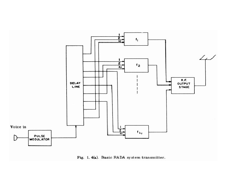
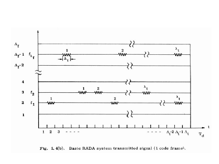
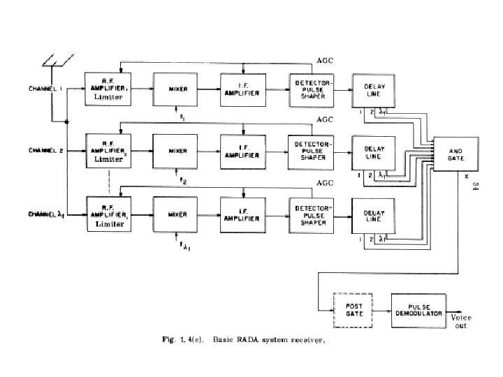
The Basic RADA System The transmitter, transmitted waveform, and receiver of this "basic RADA system" are shown in Figs. 1. 4(a), 1. 4(b), and 1. 4(c). In the transmitter of Fig. 1. 4(a), the information is subject to some type of pulse modulation (source encoding). Subsequently, each modulator output pulse causes the transmission, through RADA encoding, of a group of pulses (termed a "frame") coded within a "matrix of time frequency cells" (or simply matrix) which occupy a time interval Td seconds long and a frequency band W cycles per second wide centered at the nominal RADA system center frequency. Further, the matrix contains Λt equal "time slots" within the time interval of length Td and Λf equal "frequency channels" within the frequency band (of width W ).
In each frame, pulses are transmitted in λt out of the Λt "time slots" within λf out of the Λf "frequency channels. " Addressing to particular receivers is accomplished by the choice of time frequency cells in which pulses are transmitted. A representative frame has the form indicated in Fig. 1. 4(b).
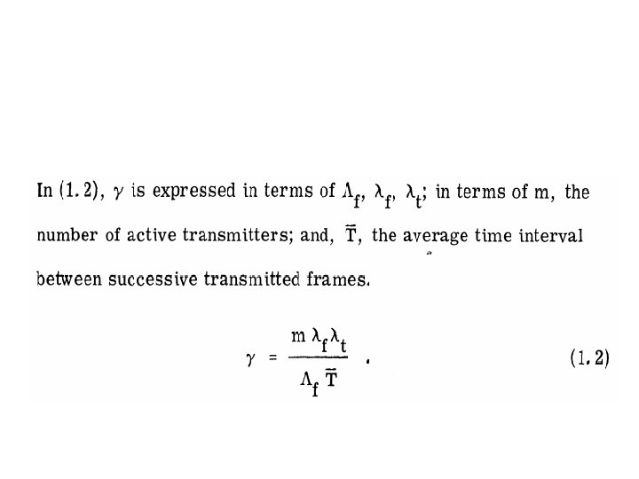
To prevent overlapping of successive frames, a frame dura tion Td is chosen which is less than or equal to the minimum interval between modulator output pulses. To minimize system bandwidth, the frame duration is usually chosen to equal the minimum interval between modulator output pulses. The average number γ of interfering pulses which occur per second on each frequency channel is an im portant parameter for the description of RADA system performance.
Whenever a group of pulses with the proper timing occurs at a receiver input, the receiver AND gate produces an output pulse. The major effect of mutual interference in this type of system is the production of error pulses at the output of the receiver AND gate.
This gate output has been indicated by an x in Fig. 1. 4(c). When the times at which the AND gate might be triggered by a message pulse can be predicted from the reception of previous message pulses, a receiver "post gate" may be used to gate some of the interference from the AND gate output. The post gate is characterized by the time interval Tp (the "gate interval") that it remains open. The use of a post gate implies receiver time synchronization, since the gate inter val must be synchronized with the times at which there are AND gate output message pulses.
END