Module 3 Lecture 4 Phased Array Radars Conventional


 were demonstrated")


 arrays used for")

 phased array, (b) time-delay array, (c)")


 s 2(k) w*2, 0 s 1(k) w*1 s")
 s 1(k) F F T w*N . . . … . .")


- Slides: 42
Module 3. Lecture 4. Phased Array Radars
Conventional and phased-array radar in comparison.
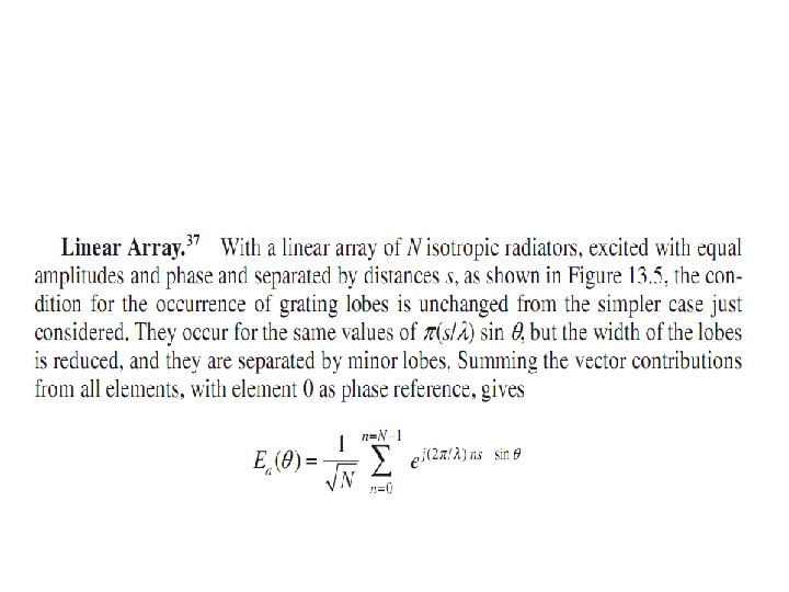
Phased Array Radars. Early radar systems used antenna arrays formed by the combination of individual radiators. Antenna characteristics are determined by the geometric position of the radiators and the amplitude and phase of their excitation.
As radars progressed to shorter wavelengths, arrays were displaced by simpler antennas such as parabolic reflectors. For modern radar applications, the advent of electronically controlled phase shifters, switches, and transmit/ receive modules has once more directed attention to array antennas.
The aperture excitation may now be modulated by controlling the phase of the individual elements to give beams that are scanned electronically.
The dramatic advantage of electronically steered phased arrays as compared to reflectors is provided by the time required to steer beams and the flexibility in steering.
While prior radars took seconds to steer to a new location, phased arrays take microseconds. In addition, the new location can be anywhere in a hemisphere. This lecture will be devoted to arrays of this type.
Phased array theory was studied intensively in the 1960 s. Technology advanced and led to a series of operational systems in the 1980 s; many publications became available.
In terms of performance improvement, ultralow sidelobes (less than -40 d. B) were demonstrated first in the 1970 s by Westinghouse Electric Corporation's AWACS (Airborne Warning and Control System) and brought about tight tolerances in construction and phase settings.
The advent of more and better computer modeling and sophisticated test equipment such as network analyzers has led to improved methods of designing well-matched apertures.
Better components such as radiating elements, phase shifters, and power dividers are now available. More economical solidstate devices and memory chips have led to precision aperture phase control with corrections for frequency and temperature variations.
Solid-state microwave devices hold great promise for future systems where a solid-state module is associated with each radiating element; improvements in terms of aperture control, reliability, and efficiency continue.
Phased arrays can be controlled adaptively, particularly for sidelobe cancellation. This is an area where theory and understanding have advanced much.
Also great progress has been made with indoor near-field antenna ranges, where computer-controlled precision two-dimensional radiation patterns are derived at multiple frequencies and with scanning.
Phased arrays are very expensive. As technology advances, costs are expected to be reduced. At the same time, the quest for better performance with lower sidelobes and wider bandwidth keeps the costs high.
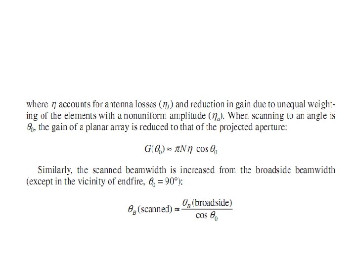
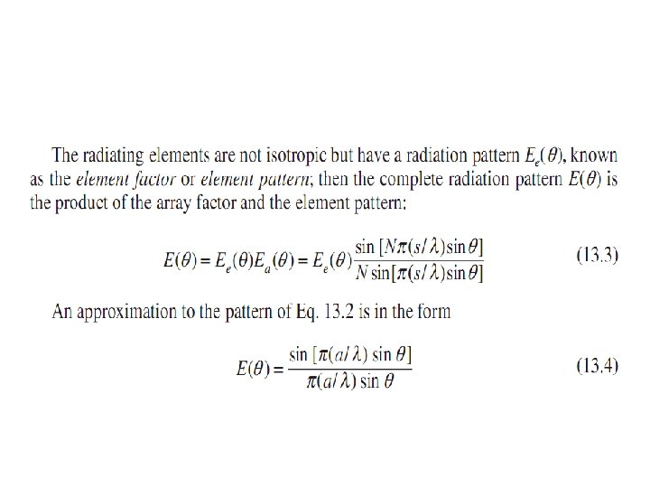
Phased Array Antennas. The phased array antenna has an aperture that is assembled from a great many similar radiating elements, such as slots, dipoles, or patches, each element being individually controlled in phase and amplitude. Accurately predictable radiation patterns and beam-pointing directions can be achieved.
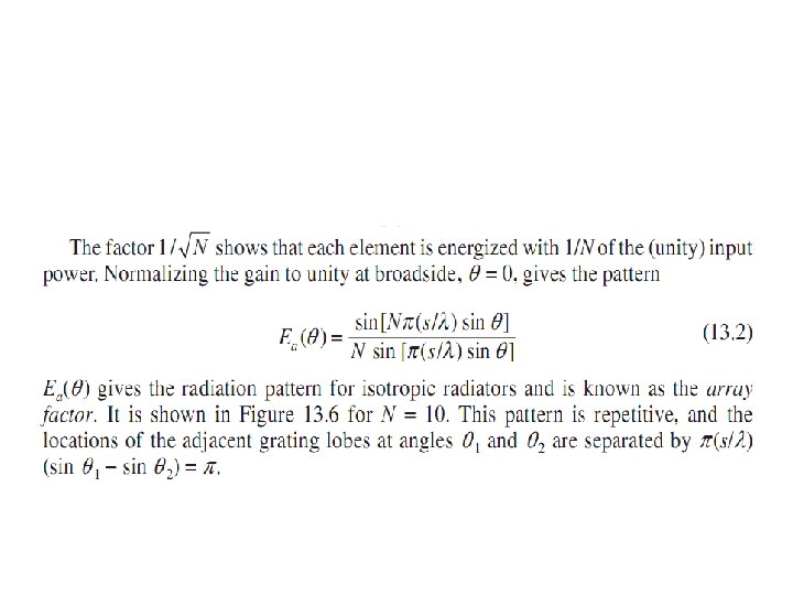
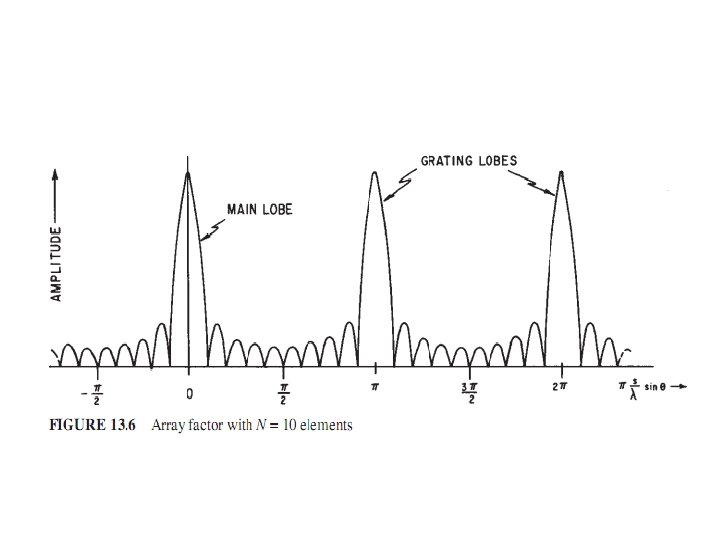
The general planar array characteristics are readily obtained from a few simple equations. With the elements spaced by λ/2 (λ - wavelength) to avoid the generation of multiple beams (grating lobes),
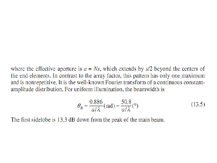
the number of radiating elements N for a pencil beam is approximately related to the beamwidth by
Conformal Arrays. Phased arrays may conform to curved surfaces as required, for example, for flush-mounting on aircraft or missiles.
If the surface has a large radius of curvature so that all the radiating elements point in substantially the same direction, then the characteristics are similar to those of a planar array (even though the exact 3 D position of the element has to be taken into account to calculate the required phase).
A small radius of curvature is found with cylindrical (or spherical) arrays used for 360° coverage. Elements are switched to avoid sections of the antenna where they point away from the desired beam direction.
Difficulties may be encountered in matching the radiating elements and in maintaining polarization purity. The discussion in this chapter will concentrate on planar phased arrays, rather than conformal arrays.
Scanning of Arrays Generation of scanned beams: (a) phased array, (b) time-delay array, (c) frequency-scanned array, and (d) Blass-type array
Direction Of Arrival estimation Plane wave …… 1 2 3 4 5 6 7 …… N-3 N-2 N-1 N d phase delay
Beamforming …… 1 2 3 1, , k 2, , k 3, , k 4 4, , k 5 6 5, , k 6, , k 7 …… N-3 N-2 N-1 N N-3, , k N-2, , k N-1, , k N, , k 7, , k …… phase shifters
Basic phased array configurations s. N(k) s 2(k) w*2, 0 s 1(k) w*1 s 1(k) w*2, 1 Z-1 w*1, 0 Narrowband . . . Z-1 w*N, k-1 . . . w*N, 1 Z-1 . . . w*N, 0 Z-1 w*2, k-1 Z-1 w*1, 1 . . . w*N s. N(k) Z-1 w*1, k-1 broadband phased array (fixed/adaptive) configurations-time domain
s 2(k) s 1(k) F F T w*N . . . … . . . I F F T + - MSE w*2 F F T … s. N(k) F F T … Basic phased array configurations w*1 broadband phased array (fixed/adaptive) configuration-frequency domain
ARRAY THEORY Array with Two Elements. Figure shows two isotropic radiators that are spaced by a distance s and excited with equal amplitude and phase.
Radiation pattern of two isotropic radiators
With unity input
Linear array with N radiators uniformly spaced by a distance s
END.