MODULE 1 DESIGN OF DEWATERING SYSTEMS DESIGN OF


- distance to the source of seepage-determined from field pumping")
√k R = radius of influence (m) C’")


 The head reduction (H-h 0) at a")


 Determinaion of wellpoint spacing (s) Assuming that h 0=h. D and head difference")


- Slides: 57
MODULE 1 DESIGN OF DEWATERING SYSTEMS
DESIGN OF DEWATERING SYSTEMS Dewatering system should be capable of: 1. Lowering the GWT upto a required depth 2. Intercepting seepage into the excavation 3. Remove the surface water which would otherwise affect the operation of dewatering system or construction
DESIGN OF DEWATERING SYSTEMS Selection of suitable dewatering system depends on 1. Geological, soil and water table conditions at the site 2. Magnitude of the excavation 3. Surface water runoff 4. Construction requirements
1. Subsoil investigation Grain size distribution and permeability are two important factors to be determined Depth and spacing of the borings have to be properly planned to ascertain the thickness of stratified soils Samples should be taken at frequent intervals to identify soil type, permeability of soil and layers of clay or other impervious material Position of WT and overburden pressure should be carefully recorded
Permeability of soil- by HAZEN’S EMPIRICAL RELATION K= C 1 D 210 D 10 = diameter of particle (cm) the size of the sieve through which only 10% of the soil grains pass k C 1 = = coefficient of permeability (cm/sec) constant varying between 100 & 150 Applicable in uniform soils (Cu<2) Laboratory tests for k - Not applicable in well graded or stratified or gravelly sands For large dewatering projects, field pumping test is suitable
2. Source and water table details Source of seepage depends on 1. Geological features of the area 2. Nearby streams or other water bodies 3. Degree of perviousness of the stratum 4. Amount of draw down Source of seepage
Radius of influence (R)- distance to the source of seepage-determined from field pumping test
By SICHORDT’S equation, R= C’ (H-hw)√k R = radius of influence (m) C’ = constant (0. 9 for gravity flows) H = hw = head at the well (m) k = depth of natural WT (m) coefficient of permeability
If the well is close to river, distance from well to river, L<R/2 : -source of seepage is the river Seasonal variation of WT should be considered WT is kept at 1 to 2 m below the bottom of excavation, inorder to ensure dry working conditions
Chemical properties of ground water should be considered GW should be checked for Iron or dissolved salts because 1. Partially or fully clog the screen, filters or surrounding soil 2. Corrode the screen or metallic parts 3. Thus reduces the efficiency of dewatering systems
3. Distance of well from source of seepage Based on field condition, R or L is determined 1. If R>>>rw , an appropriate estimation of R may be sufficient, since the discharge is not much sensitive to R 2. An accurate estimation of L should be made for particular dewatering systems, since Qα 1/L
4. Effective well radius, rw Based on the installation of wells with or with out sand or gravel filter 1. Without filter- one half the outside diameter of the well screen 2. With filter-one half the outside diameter of the filter 3. Without filter but a natural filter formed around the screen due to surging- exceed one half the outside diameter of well screen -outside dia. of the well screen
5. Discharge computations Rate at which water must be removed from pervious strata should be known before designing (for the required GW lowering or pressure relief)
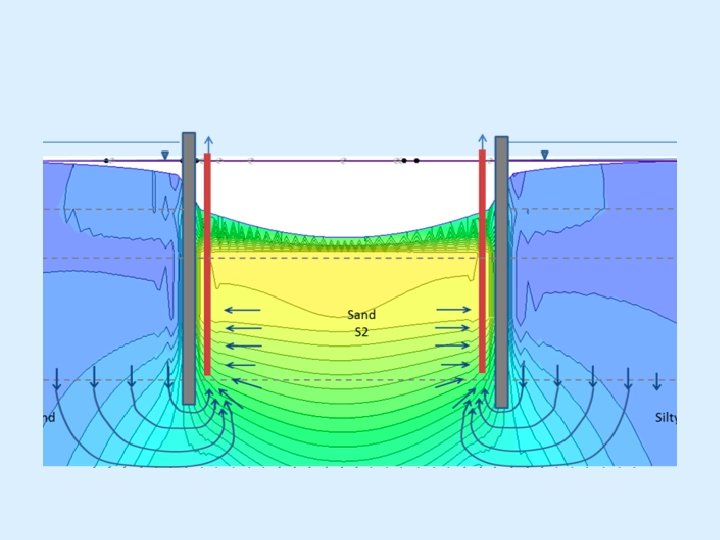
Design should decide 1. Number, size, spacing and penetration of wellpoints/wells 2. Size and capacity of collectors and pumps Fundamental relation between discharge and drawdown is required Appropriate solution for drawdown can be obtained by considering the line of closely spaced wellpoints as a drainage slot
As per IS: 9759 -1981 a) The head reduction (H-h 0) at a slot required to produce the desired residual head, h. D should be computed Where, H = head corresponding to natural WT h 0 = head at slot he = ground water level at the use Fully penetrating slot 1. Artesian flow 2. Gravity flow
Partially penetrating slot 1. Artesian flow 2. Gravity flow Where, EA = extra-length factor which depends upon the ratio W/t and L/t
Drainage from both sides Partially penetrating slot 1. Artesian flow 2. Gravity flow Fully penetrating slot Flow is twice that of drainage from one side
b) Determinaion of wellpoint spacing (s) Assuming that h 0=h. D and head difference (h 0 -hw) is small (assumed as 0. 001 H) 1. Artesian flow 2. Gravity flow c) After the wellpoint spacing (s) and head hw at wellpoint have been computed, flow Qw per wellpoint can be computed
Fully penetrating slot 1. Artesian flow 1. Gravity flow Partially penetrating slot 1. Artesian flow 1. Gravity flow same as fully penetrating slot d) The value of hw obtained should be equal to or greater than the value of hw computed from the equation for spacing calculation
6. Design of filters Character of filter materials R 50 R 15 Uniform grain size distribution (Cu= 5 -10 3 to 4) Well graded to poorly graded (nonuniform) subrounded grains 12 -58 12 -40 Well graded to poorly graded (nonuniform) angular grains 9 -30 6 -18
7. Design and selection of well screens Design of wellpoints must ensure 1. Little resistance to water flowing through screen and riser pipe 2. Prevent infiltration of sand during pumping 3. Resist corrosion by soil and water Commercially available wellpoints- brass or stainless steel screens mounted over suction pipe(galvanised, tin dipped or stainless steel)
To avoid infiltration- Mesh or slot size of screen should be smaller than D 80 or D 70 respectively Draining in silty soils- graded filter is used As per IS: 9759 -1981 - criteria for design and selection of wellpoints 1. Slot width ≤ D 70 (filter or aquifer sand) 2. Hole diameter or width < D 80 (filter or aquifer sand)
8. Selection of pumps and accessories Pumps, headers, discharge lines and power unit must be sufficient capacity to remove the required flow from the wellpoints and carry it away from the dewatered area Selection of pump and power unit depends on 1. Required discharge 2. Suction lift plus hydraulic head losses 3. Air handling capacity 4. Power available 5. Fuel economy 6. Durability of units
Centrifugal pumps are used a. To pump water in collector pipes connected to well or wellpoints b. To remove surface water from sumps If the depth of WT lowering is large (>4. 5 m)- Jet eductor pump can be used instead of multi stage wellpoint systemused upto 30 m Otherwise self-priming centrifugal pump with attached vacuum pump is used that develops 6 to 7. 5 m of vacuum.
Selection Of Power Unit Depends On 1. Initial cost of unit 2. Cost of operation including maintanance and fuel Capacity of pump from Horse power where, Total dynamic load= operating vacuum at pump intake + discharge friction losses
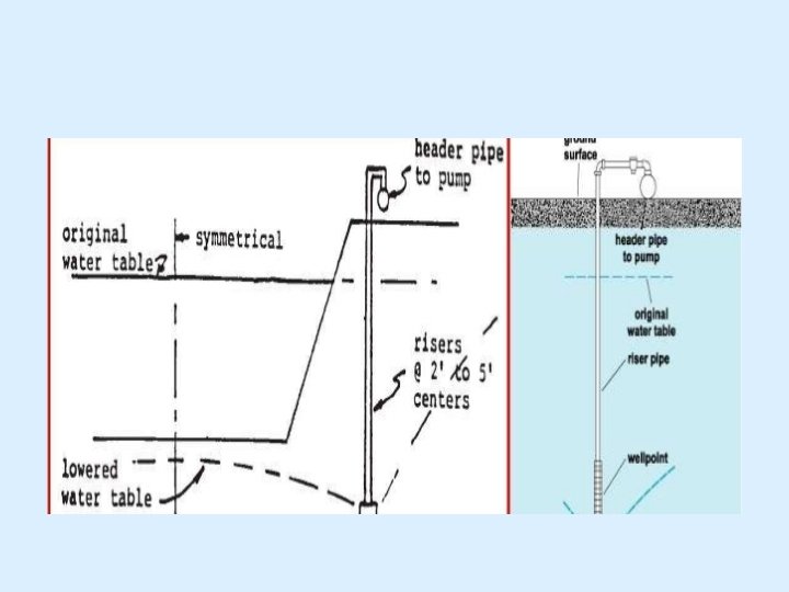
Header pipes 1. 15 to 30 cm diameter 2. Light weight steel or plastic Inlets for connection of wellpoints are provided in the header Connection is made through non-return valves Discharge line may be of steel, aluminum or plastic pipes- conduct flow with small head loss
9. Wellpointing In Deep Excavation Advantageous to use multistage wellpoints Lowest header in multistage system should be placed above the subgrade at a height not more than 4. 5 m- to ensure proper drawdown Observations should be made at every stage of operation for discharge and ground water lowering
10. Deep bored wells Design procedure is similar to that of wellpoints 15 to 45 cm diameter with 6 to 22. 5 m length Pumping is done using surface pumps with their suction pipes installed in bored wells Used efficiently upto 7. 5 m depth Pumps-centrifugal and submersible Centrifugal pumps- located on excavation slopes and connected to header pipe Submersible pumps- rising main to the surface is attached to the pump
11. Control Of Surface Water Need 1. To prevent flooding of pump resulting in failure of system 2. To prevent erosion of slopes due to uncontrolled runoff Factors to be considered 1. Duration of construction 2. Frequency of rainfall occurrence 3. Intensity of rainfall and the resulting runoff 4. Size of area to be protected 5. Available sump storage
Required measures providing Dikes: constructed at top of excavation and should be large enough to prevent overtopping of water-top of dike should be atleast 30 cm above the level of surface water to be impounded width-40 to 150 cm side slope-1 in 2 or 1 in 2. 5 Ditches-constructed with adequate allowance for silting, freeboard and storage Sumps Pumps Mulching and seeding
Drains Consists of : Conduit: - water is collected and carried away Commercial pipes have perforations 8 mm to 9 mm Filter: - it should allow only water to enter the drains Usually gravel filter with , ax 12 to 15 mm It should be designed such that seepage erosion should be prevented for continous efficiency of drains Disposal system: - gravity: pumps
Types of Drains • • • Open Drains Closed Drains Horizontal Drains Foundation Drains Blanket Drains Interceptor Drains Open Drains - form of a ditch/sump - Unskilled labor
Closed Drains • Permanent Drain • Perforated pipes laidin ditches of required depth and backfilled with filter • Pipes laid in straight lines as practically possible • Openings at 30 m to 50 m to flush out water • Manholes provided at changes in direction and at 100 m to 150 m
Horizontal Drains Ranny Drainage system is used Reinforced shafts/wells from which horizontal perforated pipes- along required length and direction Water collected in well is then pumped out Not used in stratified soil
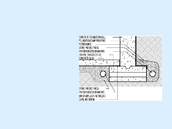
Foundation Drains It consists of perforated pipes with open joints Suitable filter should be provided Collected water disposed off by gravity flow through storm drain system If that not possible water is directed to sump pit and pumped out
Blanket Drains Beneath dams or basement slab floor, continuous blanket drains are provided It provides a highly permeable drainage path for removal of GW acting against slab Uplift pressure is reduced Seepage is prevented It consists of coarse filter cum collector in contact with the underside of the dam/floor slab, then a fine filter layer which is in contact with soil. It is connected to drainage pipe where disposal is by gravity It can also be provided below pavements to prevent capillary flow upward
Interceptor Drains To lower GWT below pavements Permit easy lateral drainage Theses drains keep the base and subgrade soils dry so as to maintain adequate strength and stability It keeps away the surface and near surface water It prevents the underground flow of water into pavements Excess pore pressure development is prevented
Interceptor Drains Applications : Highways constructed in a side hills Highways in flat terrains Airport runways
Stabilization by Thermal Methods 1. Heating 2. Freezing Heating or Cooling Soil can cause changes in the properties of soil Comparatively Expensive
Stabilization by Heating Higher the input of heat per mass of soil, greater will be the stabilization Combustion is most effective if conducted within the stratum of the soil to be stabilized. Liquid or gas fuels are burned in boreholes or by injecting hot airs into it Boreholes of dia. 15 to. 2 m can produce 1. 3 to 2. 5 m dia of stabilized zones after continuous treatment for 10 days
Small increase in temperature increase the strength due to : - Reduction in electric repulsion between particles Flow of pore water due to thermal gradient Reduction of moisture content due to increased evaporation
Temp. Range Changes in soil Properties Abt. 100 o. C Causes drying of soil Significant increase in strength Decrease in compressibility Abt. 500 o. C Causes permanent changes in clay structure Decrease in plasticity and moisture adsorption capacity Abt. 1000 o. C Causes fusion of clay particles into a solid substance like brick
For stabilizing 1 m 3 of soil -50 to 100 l of fuel oil is required Used to strengthen loessial soils (economical than pile foundation). It is only applicable to unsaturated soils Expansive soil– non expansive soil This method is favorably used when site is located near a large and inexpensive heat source Application Immobilization of radioactive or contaminated soil Densification and stabilization
Ground freezing Where soil needs to be stabilized so it will not collapse next to excavations, or to prevent contaminates spilled into soil from being leached away. Ground freezing has been used for at least one hundred years. Frozen soil can be as hard as concrete. It is far stronger and less previous than the unfrozen ground
On reduction of heat initially the strength of soil is reduced But when the soil starts freezing below 0 o. C, the soil strength rapidly increases with the decrease in temp. Bearing soils can be achieved by artificially freezing the soil. Pipes are run through the soil to be frozen, and then refrigerants are run through the pipes to freeze the soil. Once the freezing is initiated the porewater around the refrigerant pipes begin to freeze and with the continued exposure the ice layer expands until it comes in contact with the ice spreading out from the adjacent refrigerant pipes. Thus a continous wall is formed Pore water may be stationary or moving at a rate of less than 2 m/day
Example
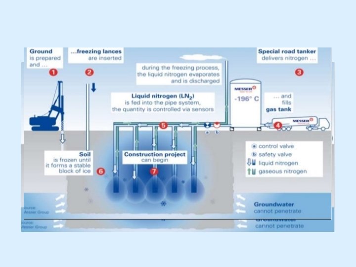
GROUND FREEZING: Ground freezing is the use of refrigeration to convert in-situ pore water to ice. The ice then acts as a cement or glue, bonding together adjacent particles of soil or blocks of rock to increase their combined strength and make them impervious. The ground freezing considerations are Thermal analysis Refrigeration system geometry Thermal properties of soil and rock freezing rates, Energy requirements, Coolant/ refrigerant distribution system analysis.
Use of expandable liquid refrigerants - liquid nitrogen, liquid carbon dioxide, liquid propane Relatively simple method Freeze pipes are installed 1 m centres; sufficiently vented Liquid nitrogen is injected and allowed to boil in these pipes Freezing takes place very rapidly Frozen zone is irregular Energy consumption is very high
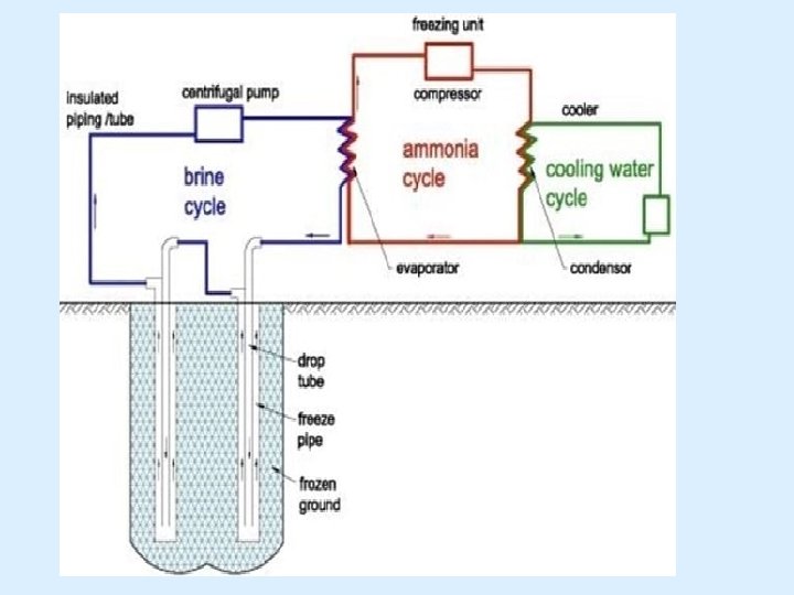
In situ pumped loop method via secondary coolant The primary source of refrigeration – ammonia/ freon refrigerant plant The coolant refrigerant system consists of a closed loop supply manifold connected to a number of parallel connected freeze pipes placed in the ground and to a return manifold Coolant is circulated into the feed pipes (25 to 75 mm dia) and return through the annular space between feed pipe and ground freeze pipes ( 100 to 200 mm dia) sealed at lower ends When coolant returns to the soil it produces freezing Conventional coolant- brine solution –( 10 to 23% of sodium chloride in water) Other coolants-Diesel oil , propane & glycol water mixtures
Method is simple and straight forward But difficult to employ Energy required for maintenance is lower than the initial consumption of energy Thermocouples are installed midway between freeze pipes to check the ground temperature Applicable for sands or cohesionless silts when GW is in the vicinity and is stationary
GROUND FREEZING APPLICATIONS: Temporary underpinning Temporary support for an excavation Prevention of groundwater flow into excavated area Temporary slope stabilization Temporary containment of toxic/hazardous waste contamination
Thank you