
ModulatorBased High Bandwidth Optical Links for HEP Experiments
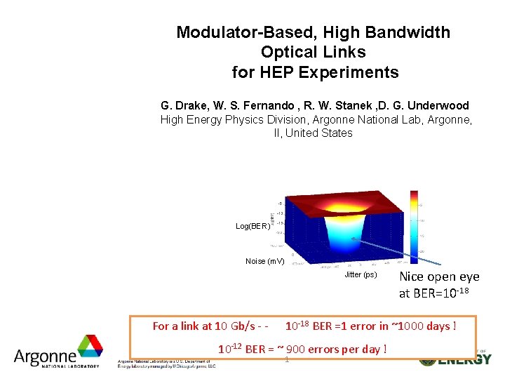
Modulator-Based, High Bandwidth Optical Links for HEP Experiments G. Drake, W. S. Fernando , R. W. Stanek , D. G. Underwood High Energy Physics Division, Argonne National Lab, Argonne, Il, United States Log(BER) Noise (m. V) Jitter (ps) For a link at 10 Gb/s - - Nice open eye at BER=10 -18 BER =1 error in ~1000 days ! 10 -12 BER = ~ 900 errors per day ! 1

Electro-Optical Modulators • Two methods for optical data transmission – Direct modulation of light: common in short distance, short wave length communication, all current LHC experiments use this technology Elec. Tx Current driver Laser (VCSEL) Optical Tx Elec. Rx Receiver PIN diodes Optical Rx – Indirect modulation of light: long distance, long wave length communication. ATLAS Tile. Cal will test this technology in 2013 (demonstrator) for use in Phase 2 upgrade Laser (CW) Elec. Tx Elec. Rx Voltage driver Modulator Receiver PIN diodes Optical Tx Optical Rx Monolithically integrated Silicon photonic device 2
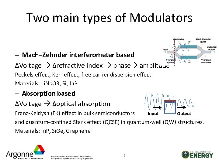
Two main types of Modulators – Mach–Zehnder interferometer based ΔVoltage Δrefractive index phase amplitude Pockels effect, Kerr effect, free carrier dispersion effect Materials: Li. Nb. O 3, Si, In. P – Absorption based ΔVoltage Δoptical absorption Output Input Franz-Keldysh (FK) effect in bulk semiconductors and quantum-confined Stark effect (QCSE) in quantum-well (QW) structures. Materials: In. P, Si. Ge, Graphene 3
Modulating Materials for HEP • Li. Nb. O 3 - based on the crystal property – High bandwidth, tested rad-hard, very long (~5 cm), expensive, high drive voltages • In. P - based on the crystal property – Very High bandwidths, should be rad-hard, small (~2 mm), low drive voltages, expensive at present, special-purpose technology • Si - based on the free carrier dispersion effect – High bandwidth, rad-hard (? ), small (~1 mm), inexpensive, could monolithically integrate, commercially available, use existing Si Technology 4
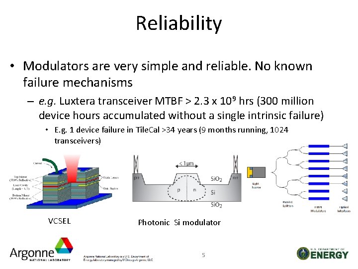
Reliability • Modulators are very simple and reliable. No known failure mechanisms – e. g. Luxtera transceiver MTBF > 2. 3 x 10⁹ hrs (300 million device hours accumulated without a single intrinsic failure) • E. g. 1 device failure in Tile. Cal >34 years (9 months running, 1024 transceivers) VCSEL Photonic Si modulator 5
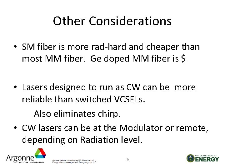
Other Considerations • SM fiber is more rad-hard and cheaper than most MM fiber. Ge doped MM fiber is $ • Lasers designed to run as CW can be more reliable than switched VCSELs. Also eliminates chirp. • CW lasers can be at the Modulator or remote, depending on Radiation level. 6
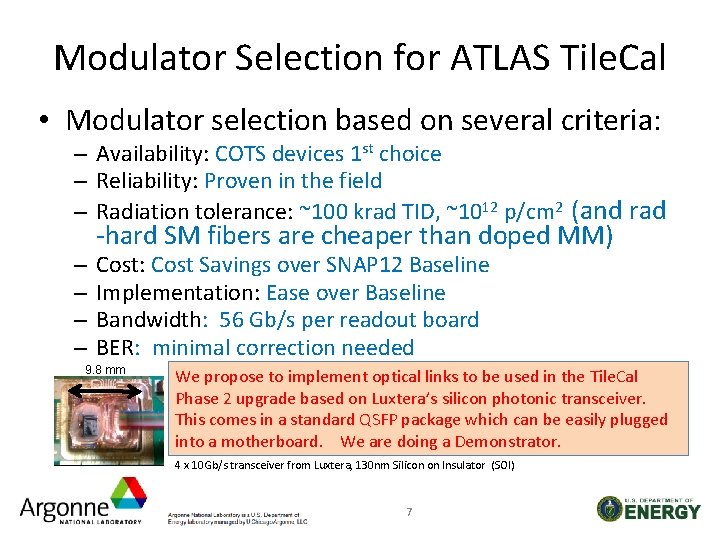
Modulator Selection for ATLAS Tile. Cal • Modulator selection based on several criteria: – Availability: COTS devices 1 st choice – Reliability: Proven in the field – Radiation tolerance: ~100 krad TID, ~1012 p/cm 2 (and rad – – -hard SM fibers are cheaper than doped MM) Cost: Cost Savings over SNAP 12 Baseline Implementation: Ease over Baseline Bandwidth: 56 Gb/s per readout board BER: minimal correction needed 9. 8 mm We propose to implement optical links to be used in the Tile. Cal Phase 2 upgrade based on Luxtera’s silicon photonic transceiver. This comes in a standard QSFP package which can be easily plugged into a motherboard. We are doing a Demonstrator. 4 x 10 Gb/s transceiver from Luxtera, 130 nm Silicon on Insulator (SOI) 7
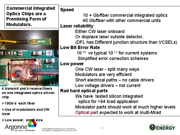
Commercial Integrated Optics Chips are a Promising Form of Modulators. 1 cm laser 4 transmit and 4 receive fibers on one integrated optics silicon chip Ø 10 Gb/s each fiber ØUse of modulators and CW laser Speed 10 + Gb/fiber commercial integrated optics 40 Gb/fiber with other commercial units Laser reliability Either CW laser onboard Or displace laser outside detector. (DFL has Different junction structure than VCSELs) Low Bit Error Rate 10 -18 vs typical 10 -12 for current systems Simplified error correction schemes Low power One CW laser - split many ways Modulators are very efficient Short electrical paths – no cable drivers Low voltage drivers – not current Rad hard optical parts We have tested silicon integrated optics for >64 krad application Modulator parts should work at much higher levels Optical part expected to work at multi-Mrad ØLow power, small size 8
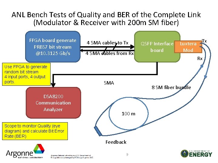
ANL Bench Tests of Quality and BER of the Complete Link (Modulator & Receiver with 200 m SM fiber) FPGA board generate PRBS 7 bit stream @10. 3125 Gb/s Use FPGA to generate random bit stream 4 input ports, 4 output ports. DSA 8200 Communication Analyzer Scope to monitor Quality (eye diagram) and calculate Bit Error Rate (BER) 4 SMA cables to Tx 4 SMA cables from Rx SMA QSFP Interface board Luxtera Tx Mod Rx 8 SM fiber bundle 100 m Feedback 9
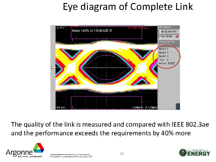
Eye diagram of Complete Link Mask 140% of 10 GBASE-R The quality of the link is measured and compared with IEEE 802. 3 ae and the performance exceeds the requirements by 40% more 10
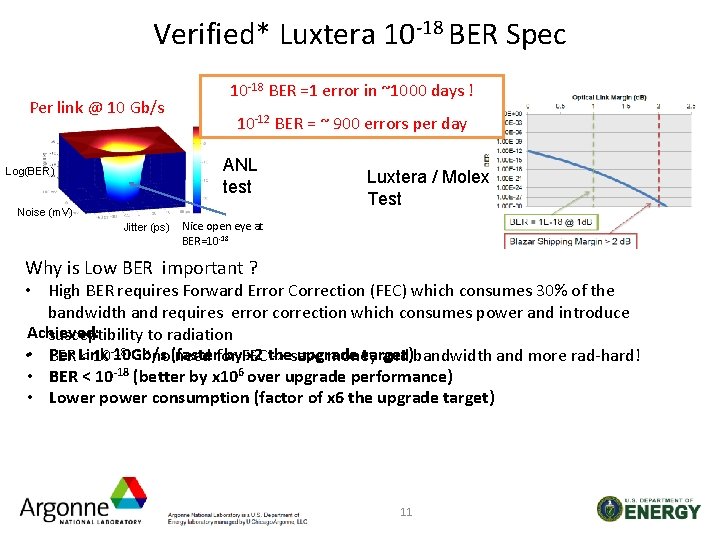
Verified* Luxtera 10 -18 BER Spec Per link @ 10 Gb/s 10 -18 BER =1 error in ~1000 days ! 10 -12 BER = ~ 900 errors per day ANL test Log(BER) Noise (m. V) Jitter (ps) Luxtera / Molex Test Nice open eye at BER=10 -18 Why is Low BER important ? • High BER requires Forward Error Correction (FEC) which consumes 30% of the bandwidth and requires error correction which consumes power and introduce Achieved: susceptibility to radiation ~ ~ no(faster Per Link 10 Gb/s by. FEC x 2 the upgrade target) • BER < 10 -18 need for -> save money and bandwidth and more rad-hard! • BER < 10 -18 (better by x 106 over upgrade performance) • Lower power consumption (factor of x 6 the upgrade target) 11
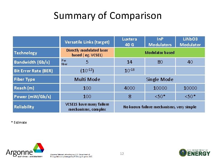
Summary of Comparison Versatile Links (target) Technology Bandwidth (Gb/s) Bit Error Rate (BER) Directly modulated laser based ( eg. VCSEL) Per fiber Luxtera 40 G In. P Modulators Li. Nb. O 3 Modulator based 5 14 (10 -12) 10 -18 80 40 Fiber Type Multi Mode Reach (m) 100 4000 10000 Power (m. W/Gb/s) 100 8 <50* Reliability VCSELS have many failure mechanisms, complex Single Mode No known failure mechanisms, very simple * Estimate 12
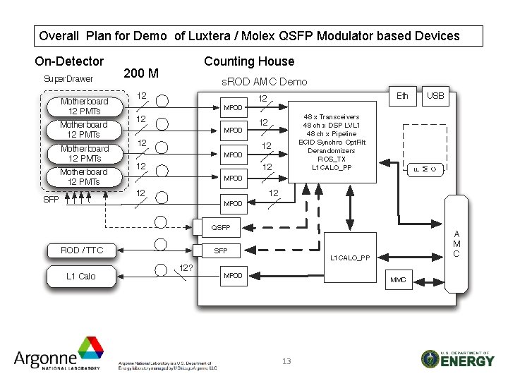
Overall Plan for Demo of Luxtera / Molex QSFP Modulator based Devices On-Detector 200 M Counting House 13
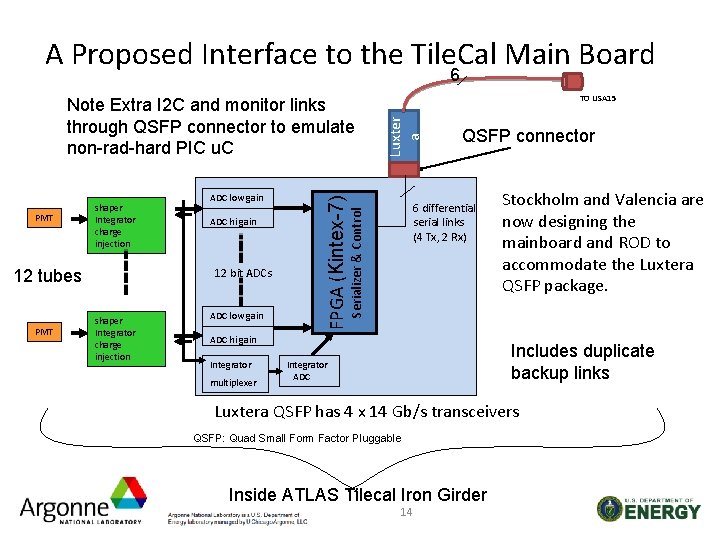
A Proposed Interface to the Tile. Cal Main Board 6 12 tubes PMT ADC low gain ADC hi gain 12 bit ADCs shaper Integrator charge injection ADC low gain Luxter a QSFP connector 6 differential serial links (4 Tx, 2 Rx) Serializer & Control PMT shaper Integrator charge injection TO USA 15 FPGA (Kintex-7) Note Extra I 2 C and monitor links through QSFP connector to emulate non-rad-hard PIC u. C ADC hi gain Integrator multiplexer Stockholm and Valencia are now designing the mainboard and ROD to accommodate the Luxtera QSFP package. Includes duplicate backup links Integrator ADC Luxtera QSFP has 4 x 14 Gb/s transceivers QSFP: Quad Small Form Factor Pluggable Inside ATLAS Tilecal Iron Girder 14
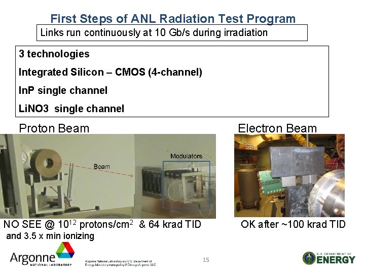
First Steps of ANL Radiation Test Program Links run continuously at 10 Gb/s during irradiation 3 technologies Integrated Silicon – CMOS (4 -channel) In. P single channel Li. NO 3 single channel Proton Beam Electron Beam NO SEE @ 1012 protons/cm 2 & 64 krad TID OK after ~100 krad TID and 3. 5 x min ionizing 15
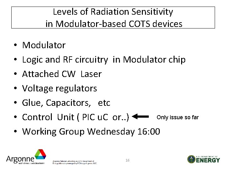
Levels of Radiation Sensitivity in Modulator-based COTS devices • • Modulator Logic and RF circuitry in Modulator chip Attached CW Laser Voltage regulators Glue, Capacitors, etc Only issue so far Control Unit ( PIC u. C or. . ) Working Group Wednesday 16: 00 16
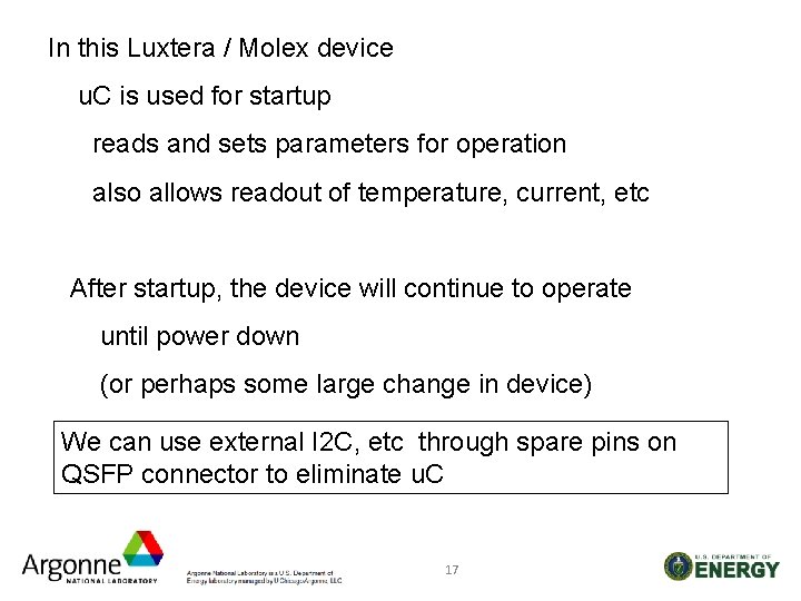
In this Luxtera / Molex device u. C is used for startup reads and sets parameters for operation also allows readout of temperature, current, etc After startup, the device will continue to operate until power down (or perhaps some large change in device) We can use external I 2 C, etc through spare pins on QSFP connector to eliminate u. C 17
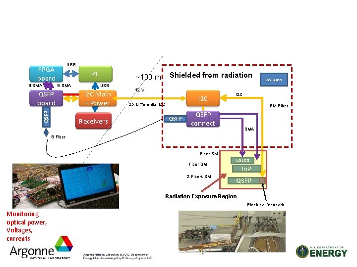
USB FPGA board 8 SMA PC 8 SMA QSFP board Shielded from radiation ~100 m USB I 2 C Main + Power Receivers 12 V I 2 C 2 x Differential I 2 C CW Lasers I 2 C PM Fiber QSFP connect SMA 8 Fiber SM 2 Fibers SM Li. Nb. O 3 In. P QSFP Radiation Exposure Region Electrical feedback Monitoring optical power, Voltages, currents 18
Summary: Modulators • Modulators are a robust replacement for VCSEL-based optical readout: – High Speed: >10 Gb/s. No speed limits – Reliable: Rad hard, BER ~10 -18. MTBF ~2. 3 x 10⁹ hrs • We have proposed an optical link be used in Tile. Cal and have built a prototype link based on Luxtera transceiver – Characterized it for use @ 10 Gb/s with < 10 -18 BER – Tested radiation hardness up to 8 x 10¹¹ p/cm 2 • No SEU at this level • Need some changes to the controller ---- • Investigating other COTS modulator devices made of other materials. • Investigating options to use modulators in very high radiation environments such as tracker upgrades 19
Development of Free-Space (fiberless) Links Utilizing Modulators • Advantages: – Low latency (no velocity factor) – Work over distances from few mm (internal triggers) to ~Km (counting house) or far ( to satellite orbit) – Low mass – No fiber routing – Communicate between ID layers for trigger decisions. 20
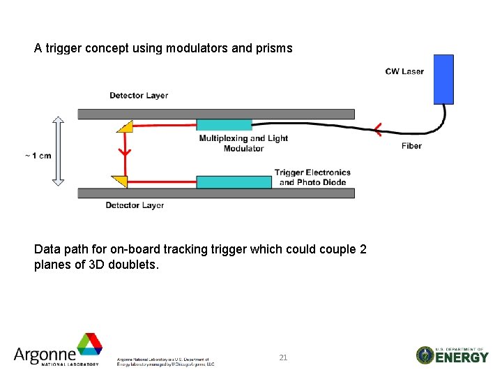
A trigger concept using modulators and prisms Data path for on-board tracking trigger which could couple 2 planes of 3 D doublets. 21
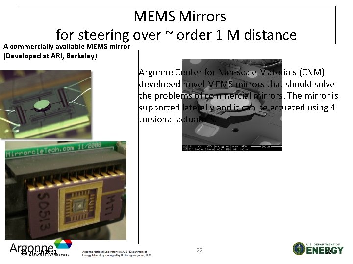
MEMS Mirrors for steering over ~ order 1 M distance A commercially available MEMS mirror (Developed at ARI, Berkeley) Argonne Center for Nan-scale Materials (CNM) developed novel MEMS mirrors that should solve the problems of commercial mirrors. The mirror is supported laterally and it can be actuated using 4 torsional actuators. 12 March 2021 22 22
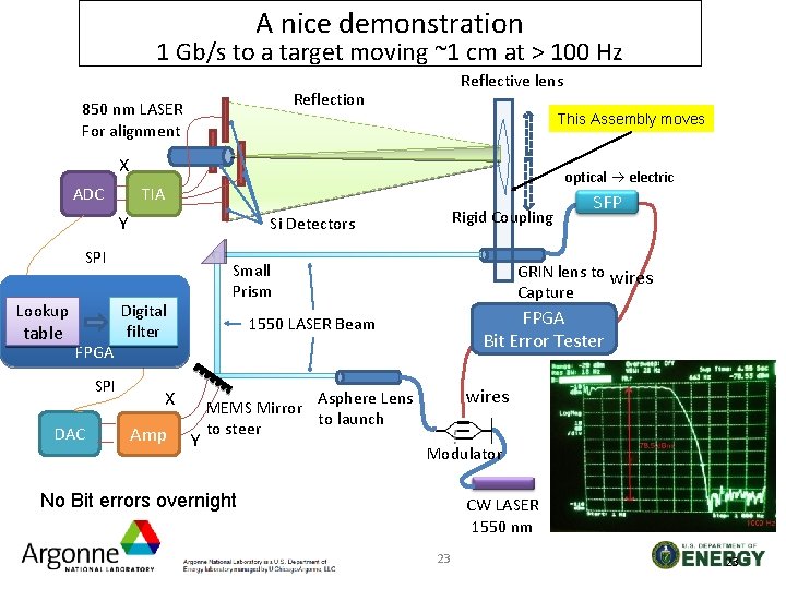
A nice demonstration 1 Gb/s to a target moving ~1 cm at > 100 Hz Reflective lens Reflection 850 nm LASER For alignment This Assembly moves X ADC optical electric TIA Y Si Detectors SPI Lookup table FPGA SPI DAC Rigid Coupling Small Prism Digital filter Amp GRIN lens to wires Capture FPGA Bit Error Tester 1550 LASER Beam X Y SFP wires Asphere Lens MEMS Mirror to launch to steer Modulator No Bit errors overnight CW LASER 1550 nm 23 23
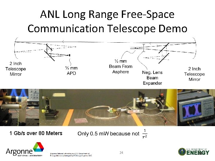
ANL Long Range Free-Space Communication Telescope Demo 1 Gb/s over 80 Meters 24 24
Modulator Plans • Radiation Test Luxtera Molex without the microcontroller Protons 3. 5 x min ioni. Gammas total dose up to 3 MR Neutrons • Radiation test components of Luxtera/Molex Voltage Regulator Laser ATLAS Tilecal Demonstrator Tests Kintex 7 FPGA Radiation test Other Devices and other materials For higher radiation environments Develop other Optical Communication capabilities 25
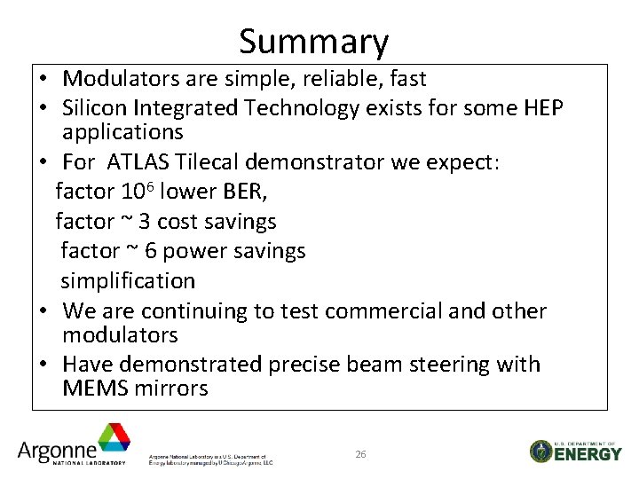
Summary • Modulators are simple, reliable, fast • Silicon Integrated Technology exists for some HEP applications • For ATLAS Tilecal demonstrator we expect: factor 106 lower BER, factor ~ 3 cost savings factor ~ 6 power savings simplification • We are continuing to test commercial and other modulators • Have demonstrated precise beam steering with MEMS mirrors 26
Backup 27
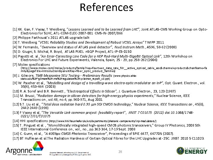
References [1] KK. Gan, F. Vasay, T Weidberg, “Lessons Learned and to be Learned from LHC”, Joint ATLAS-CMS Working Group on Opto. Electronics for SLHC, ATL-COM-ELEC-2007 -001 CMS-IN-2007/066 [2] Philippe Farthouat’s 2011 ATLAS upgrade talk [3] T. Weidberg “VCSEL Reliability Studies and Development of Robust VCSEL Arrays” TWIPP 2011 [4] W. Fernando, “Overview and status of ATLAS pixel detector”, Nucl. Instrum. Meth. , A 596, 58 -62 (2008) [5] D. Giugni, S. Michal, R. Boyd, ATLAS PIXEL n. SQP Project, ATL-IP-ES-0150 [6] Papotti et. al , “An Error-Correcting Line Code for a HEP Rad-Hard Multi-Giga. Bit Optical Link”, 12 th Workshop on Electronics For LHC and Future Experiments, Valencia, Spain, 25 - 29, pp. 258 -262 (2006) [7] Molex specifications (http: //www. molex. com/molex/products/family? key=fourteen_data_rate_fdr__active_optical_cable_aoc&channel=products&chan. Name=fa mily&page. Title=Introduction&parent. Key=fiber_optic_product_families) [8] J. Gilmore, TMB Mezzanine SEU Testing - Preliminary Results (www. physics. ohiostate. edu%2 F~gilmore%2 Fcms%2 Fregulators%2 Fcyclotron_report_v 2. ppt) [9] W. Pascher et al. , “Modelling and design of a travelling-wave electro-optic modulator on In. P”, Opt. Quant. Electron. , vol. 35(4), 453 -464 (2003) [10] R. A. Soref and B. R. Bennett , “Electrooptical Effects In Silicon”, J. Quantum Electron. , 23, 123 (1987) [11] M. Bruzzi, "Radiation damage in silicon detectors for high-energy physics experiments, " Nuclear Science, IEEE Transactions on , vol. 48, no. 4, pp. 960 -971, Aug 2001 [12] S. T. Liu et al. , "Total dose radiation hard 0. 35 μm SOI CMOS technology, " Nuclear Science, IEEE Transactions on , 45(6), 2442 -2449 (1998) [13] F Vasey et al, “The Versatile Link common project: feasibility report”, JINST 7 C 01075 (2012) doi: 10. 1088/17480221/7/01/C 01075 [14] HHI specifications (http: //www. hhi. fraunhofer. de/en/departments/photonic-components/inp-modulators/) [15] T. Pinguet et al. , "Monolithically integrated high-speed CMOS photonic transceivers, " Group IV Photonics, 2008 5 th IEEE International Conference on , vol. , no. , pp. 362 -364, 17 -19 Sept. 2008 [16] C. Gunn, et al. , “A 40 Gbps CMOS Photonics Transceiver”, Proceedings of SPIE 6477, 64770 N (2007). [17] BT Huffman et al. The Radiation Hardness of Certain Optical Fibres for the LHC Upgrades at -25 C. JINST 2010 5 C 11023. 28
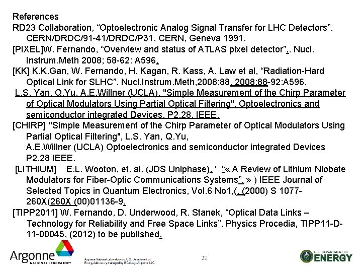
References RD 23 Collaboration, “Optoelectronic Analog Signal Transfer for LHC Detectors”. CERN/DRDC/91 -41/DRDC/P 31. CERN, Geneva 1991. [PIXEL]W. Fernando, “Overview and status of ATLAS pixel detector”, . Nucl. Instrum. Meth 2008; 58 -62: A 596. [KK] K. K. Gan, W. Fernando, H. Kagan, R. Kass, A. Law et al, “Radiation-Hard Optical Link for SLHC”. Nucl. Instrum. Meth, 2008: 88 -92: A 596. L. S. Yan, Q. Yu, A. E. Willner (UCLA), "Simple Measurement of the Chirp Parameter of Optical Modulators Using Partial Optical Filtering", Optoelectronics and semiconductor integrated Devices, P 2. 28, IEEE. [CHIRP] "Simple Measurement of the Chirp Parameter of Optical Modulators Using Partial Optical Filtering", L. S. Yan, Q. Yu, A. E. Willner (UCLA) Optoelectronics and semiconductor integrated Devices P 2. 28 IEEE. [LITHIUM] E. L. Wooton, et. al. (JDS Uniphase), ‘ “ « A Review of Lithium Niobate Modulators for Fiber-Optic Communications Systems”, » ) IEEE Journal of Selected Topics in Quantum Electronics, Vol. 6 No 1, (, (2000) S 1077260 X(260 X (00)01136 -9. [TIPP 2011] W. Fernando, D. Underwood, R. Stanek, “Optical Data Links – Technology for Reliability and Free Space Links”, Physics Procedia, TIPP 11 -D 11 -00045, (2012) to be published. 29
[DPF] W. Fernando, D. Underwood, R. Stanek “New Optical Link Technologies for HEP Experiments”, Meeting of the Division of Particles and Fields of the American Physical Society, Brown University, August, 2011 ar. Xiv: 1109. 6842 v 1. [IEEE] D. Underwood, P. De. Lurgio, G. Drake, W. Fernando, D. Lopez, G. Drake, B. Salvachua-Ferrando, R. Stanek, “Development of Low Mass Optical Readout for High Data Bandwidth Systems” IEEE Nuclear Science Symposium Conference Record (NSS/MIC), 624 -629, 2010. [IBM]W. Green, M. Rooks, L. Sekaric, and Y. Vlasov “Ultra-compact, low RF power, 10 Gb/s silicon Mach-Zehnder modulator”, Opt. Express 2007; 17106 -17113: 15. [JINST] D. Underwood, B. Salvachua-Ferrando, R. Stanek, D. Lopez, J. Liu, J. Michel, L. C. Kimerling, “New Optical Technology for low mass intelligent trigger and readout”, . JINST 5: C 07011, 2010. [In. P] 40 Gb/s In. P Modulator …………………… http: //www. hhi. fraunhofer. de/fileadmin/hhi/downloads/PC/flyer/40_Gbits_In. P_Web. pdf. [PIC] I. Galysh, K. Doherty, J. Mc. Guire, H. Heidt, D. Niemi, G. Dutchover, (The Sten. Sat Group) "Cube. Sat: Developing a Standard Bus for Picosatellites" http: //www. stensat. org/Publications/SPIE. PDF. [FPGA] Z. K. Baker, M. E. Dunham, K. Morgan, M. Pigue, M. Stettler, P. Graham, E. N. Schmierer, J. Power (Los Alamos) “Space Based FPGA Radio receiver Design, Debug, and Development of a Radiation Tolerant Computing System”. International Journal of reconfigurable Computing, Volume 2010, Article ID 546217, doi: 10. 1155/2010/546217. 30
The Future of Optical Links - Light Modulators 31
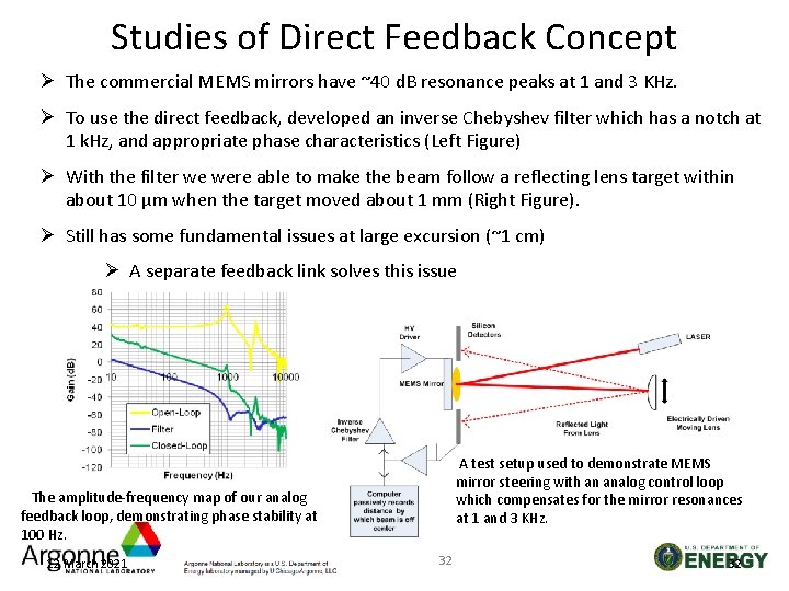
Studies of Direct Feedback Concept Ø The commercial MEMS mirrors have ~40 d. B resonance peaks at 1 and 3 KHz. Ø To use the direct feedback, developed an inverse Chebyshev filter which has a notch at 1 k. Hz, and appropriate phase characteristics (Left Figure) Ø With the filter we were able to make the beam follow a reflecting lens target within about 10 μm when the target moved about 1 mm (Right Figure). Ø Still has some fundamental issues at large excursion (~1 cm) Ø A separate feedback link solves this issue A test setup used to demonstrate MEMS mirror steering with an analog control loop which compensates for the mirror resonances at 1 and 3 KHz. The amplitude-frequency map of our analog feedback loop, demonstrating phase stability at 100 Hz. 12 March 2021 32 32
Beams in Air: Size vs Distance Due to diffraction, there is an optimum diameter for a beam for a given distance in order to reduce 1/r 2 losses Ø The Rayleigh distance acts much like Beta-Star in accelerators – Relates waist size and divergence – Depends on wavelength Ø If we start with a diameter too small for the distance of interest, the beam will diverge, and will become 1/r 2 at the receiver, and we will have large losses (We can still focus what we get to a small device like an APD or PIN diode ). This is typical of space, Satellite, etc. applications. Ø If we start with an optimum diameter, the waist can be near the receiver, and we can capture almost all the light and focus it to a small spot Ø Examples, ~ 1 mm for 1 m, ~ 50 mm for 1 Km 12 March 2021 33 33
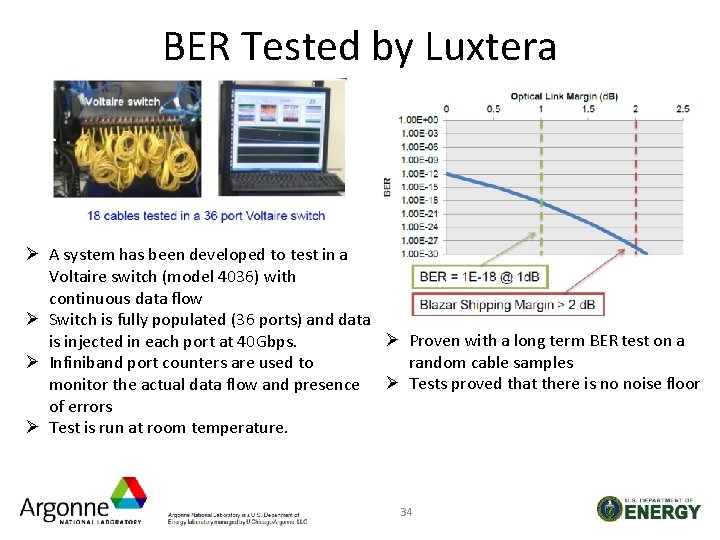
BER Tested by Luxtera Ø A system has been developed to test in a Voltaire switch (model 4036) with continuous data flow Ø Switch is fully populated (36 ports) and data Ø Proven with a long term BER test on a is injected in each port at 40 Gbps. random cable samples Ø Infiniband port counters are used to monitor the actual data flow and presence Ø Tests proved that there is no noise floor of errors Ø Test is run at room temperature. 34
- Slides: 34