
Modulation and OFDM Communication Exchange of information from
- Slides: 43
Modulation and OFDM
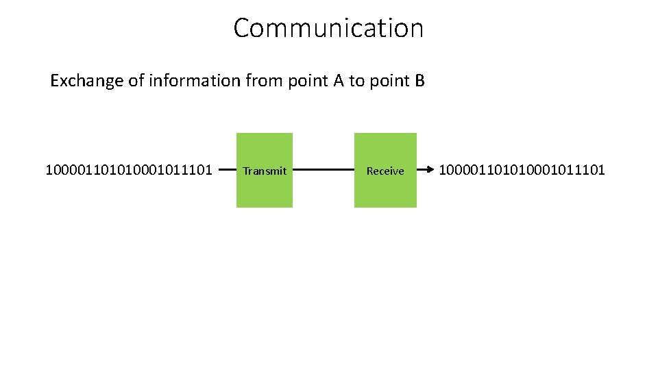
Communication Exchange of information from point A to point B 100001101010001011101 Transmit Receive 100001101010001011101
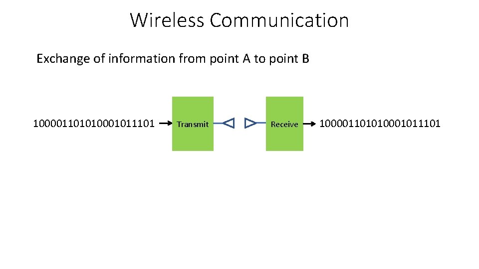
Wireless Communication Exchange of information from point A to point B 100001101010001011101 Transmit Receive 100001101010001011101
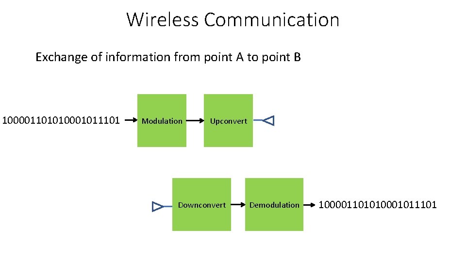
Wireless Communication Exchange of information from point A to point B 100001101010001011101 Modulation Upconvert Downconvert Demodulation 100001101010001011101
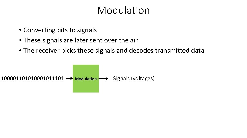
Modulation • Converting bits to signals • These signals are later sent over the air • The receiver picks these signals and decodes transmitted data 100001101010001011101 Modulation Signals (voltages)
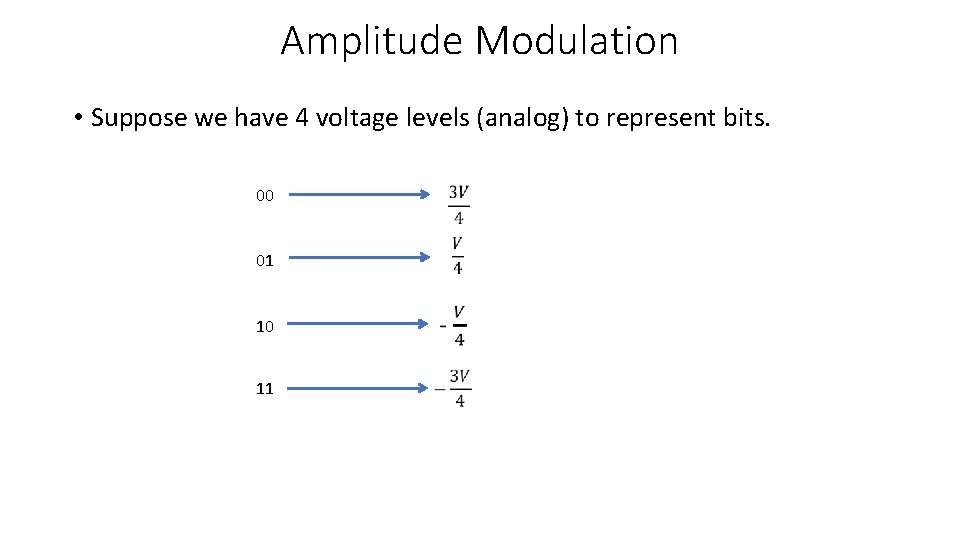
Amplitude Modulation • Suppose we have 4 voltage levels (analog) to represent bits. 00 01 10 11
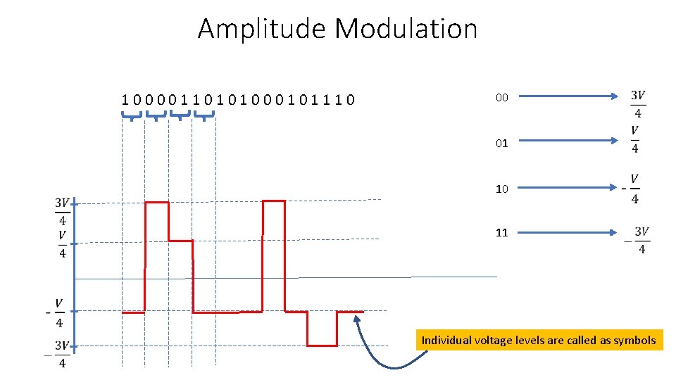
Amplitude Modulation 1 0 0 1 1 0 1 0 0 0 1 1 1 0 00 01 10 11 Individual voltage levels are called as symbols
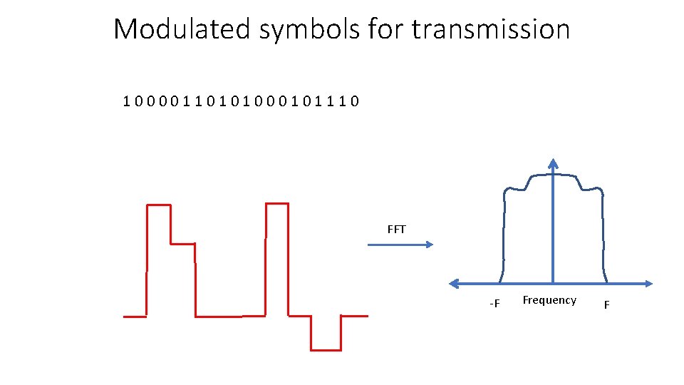
Modulated symbols for transmission 1 0 0 1 1 0 1 0 0 0 1 1 1 0 FFT -F Frequency F
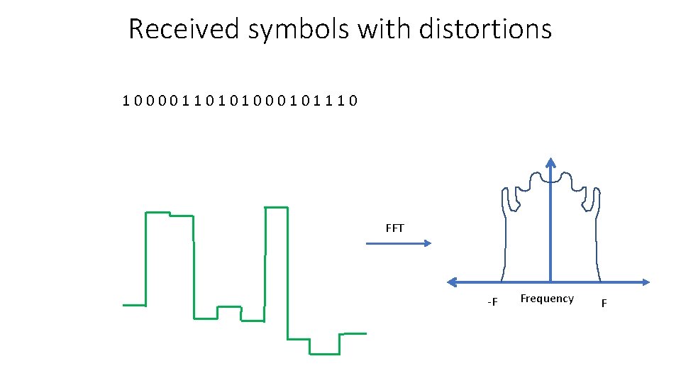
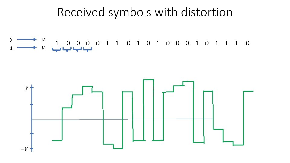
Received symbols with distortions 1 0 0 1 1 0 1 0 0 0 1 1 1 0 FFT -F Frequency F
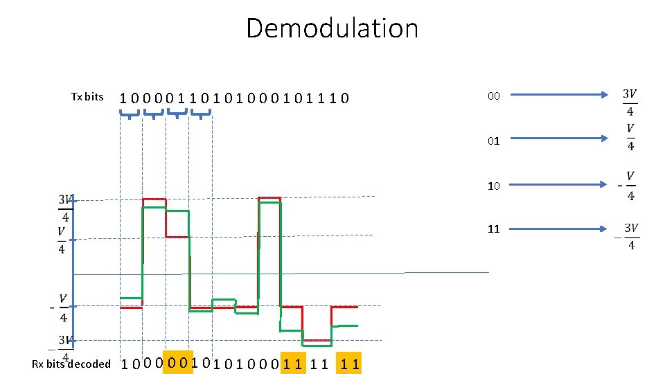
Demodulation Tx bits 1 0 0 1 1 0 1 0 0 0 1 1 1 0 00 01 11 Rx bits decoded 10 1 0 0 0 1 1 1 1
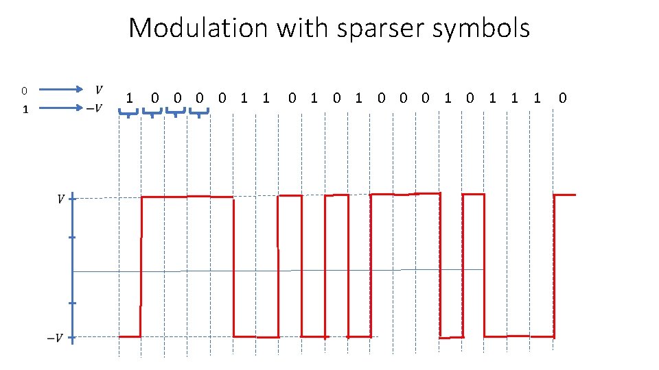
Coping up with demodulation errors • If the noise is too high, there may be too many bit flips • Symbols for modulation to be chosen as a function of this noise • For example, if we want to eliminate bit flips completely, we can choose voltage levels as follows
Modulation with sparser symbols 0 1 1 0 1 0 0 0 1 1 1 0
Received symbols with distortion 0 1 1 0 1 0 0 0 1 1 1 0
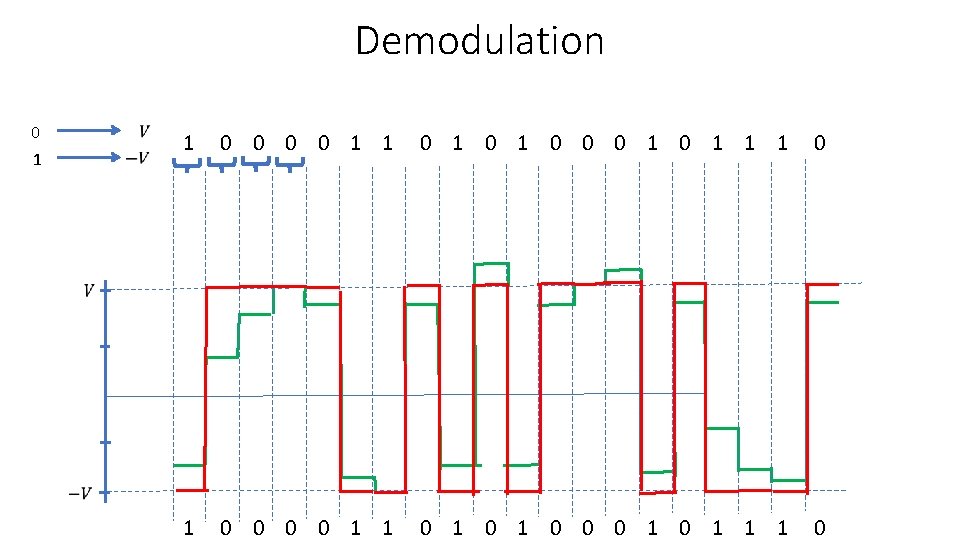
Demodulation 0 1 1 0 0 1 1 0 1 0 0 0 1 1 1 0
• That eliminated all the bit flips, which is good • However, what is the disadvantage of choosing only two voltage levels? • Takes longer to transmit, hence bit rate is very low
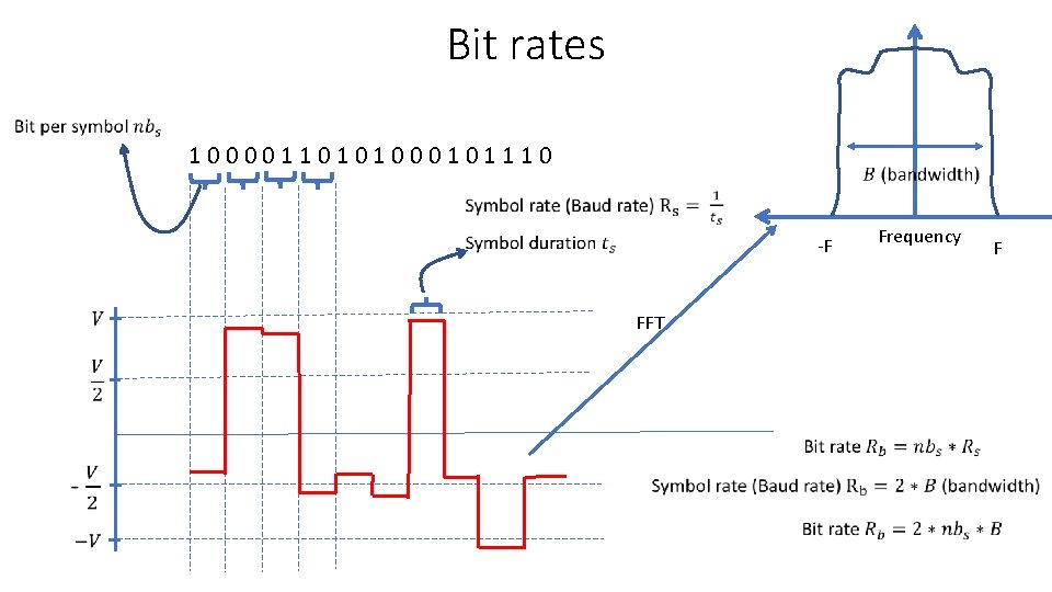
Bit rates 1 0 0 1 1 0 1 0 0 0 1 1 1 0 -F FFT Frequency F
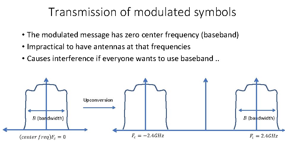
Transmission of modulated symbols • The modulated message has zero center frequency (baseband) • Impractical to have antennas at that frequencies • Causes interference if everyone wants to use baseband. . Upconversion
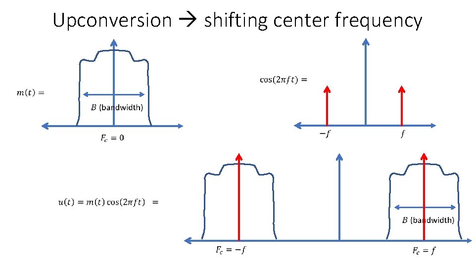
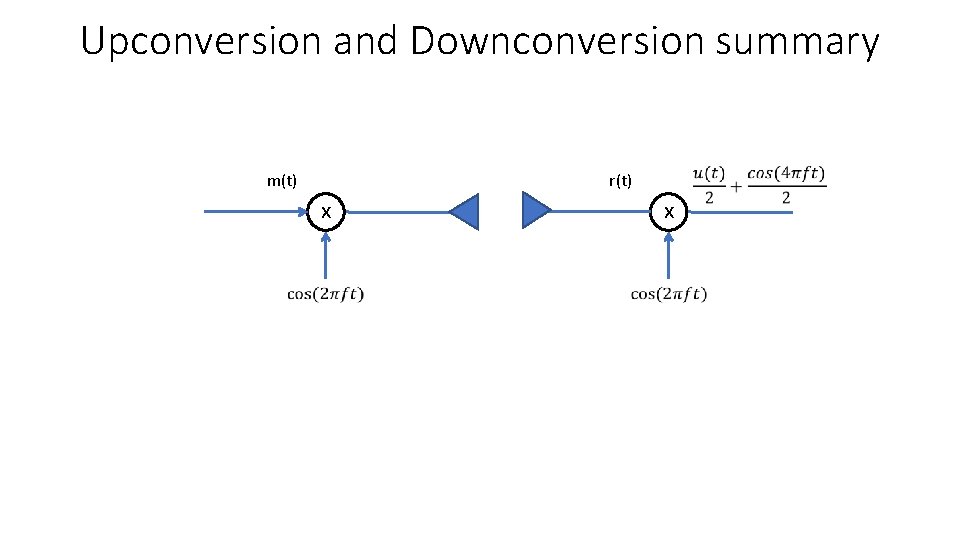
Upconversion shifting center frequency
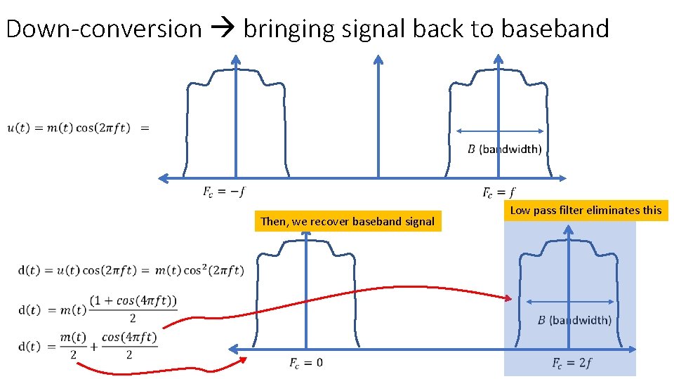
Down-conversion bringing signal back to baseband • The receiver needs to perform an operation of down-conversion • The received signal is a high frequency signal in RF • Processing the data at these frequencies needs high clock digital circuits, which is impractical • We need to convert the data back to baseband process the low frequency signals for decoding bits
Down-conversion bringing signal back to baseband Then, we recover baseband signal Low pass filter eliminates this
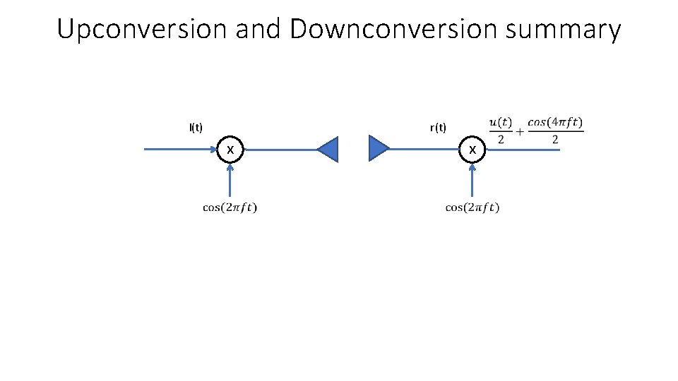
Upconversion and Downconversion summary m(t) x r(t) x
Upconversion and Downconversion summary I(t) x r(t) x
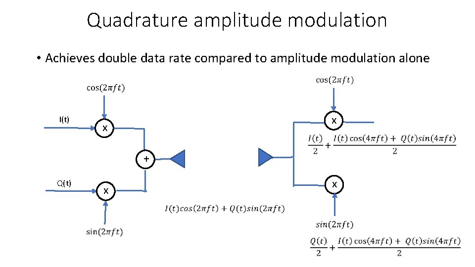
Beyond amplitude modulation • We have learnt communication with amplitude modulation • There is a simple idea to double the data rate using QAM (quadrature amplitude modulation)
Quadrature amplitude modulation • Achieves double data rate compared to amplitude modulation alone I(t) x x + Q(t) x x
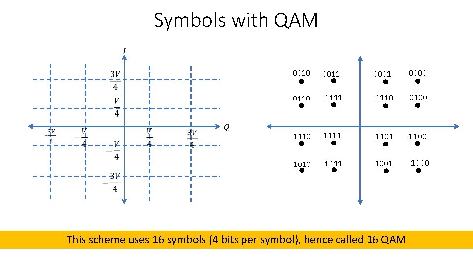
Symbols with QAM 0010 0011 0000 0111 0110 0100 1111 1100 1011 1000 This scheme uses 16 symbols (4 bits per symbol), hence called 16 QAM
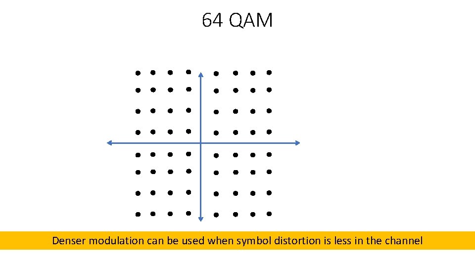
64 QAM Denser modulation can be used when symbol distortion is less in the channel
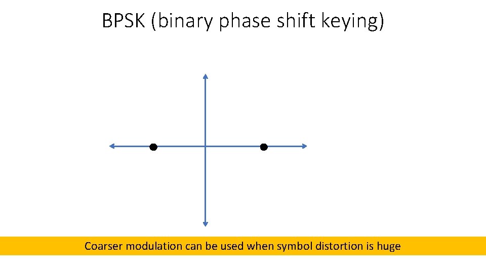
BPSK (binary phase shift keying) Coarser modulation can be used when symbol distortion is huge
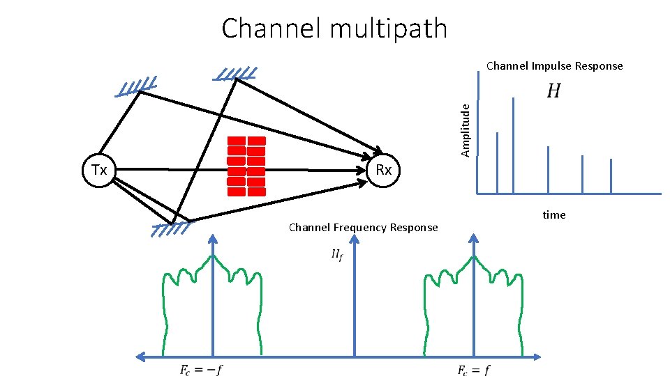
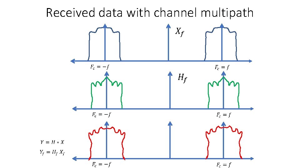
Channel multipath Channel Impulse Response Amplitude Tx Rx time Channel Frequency Response
Received data with channel multipath
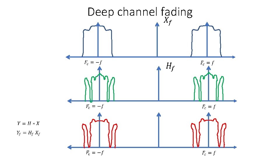
Deep channel fading
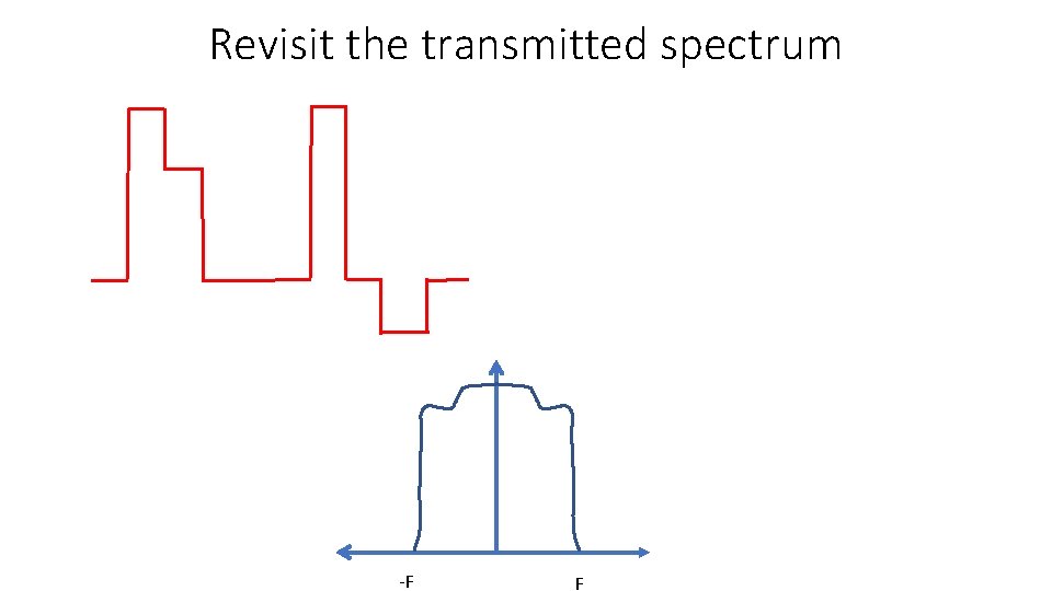
Revisit the transmitted spectrum -F F
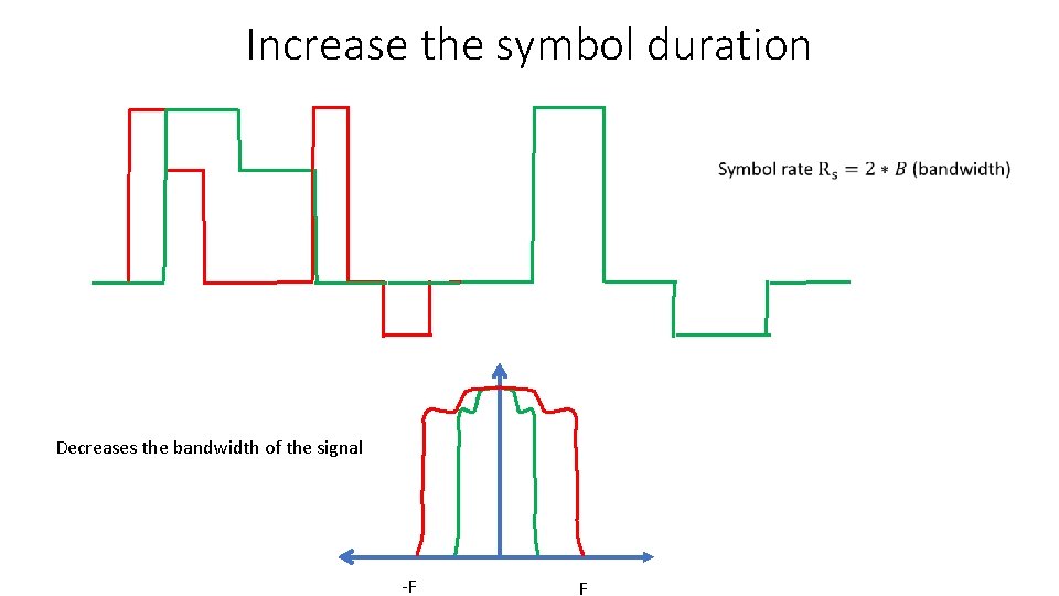
Increase the symbol duration Decreases the bandwidth of the signal -F F
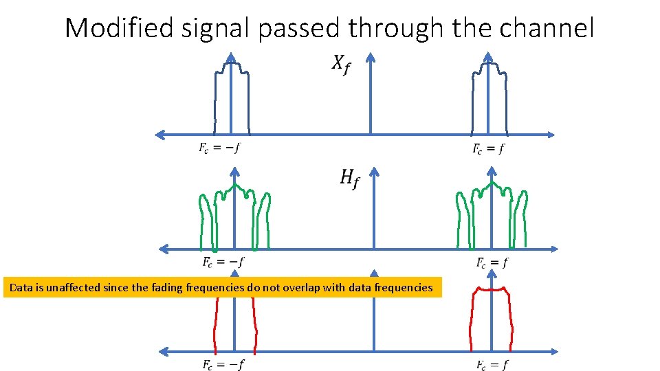
Modified signal passed through the channel Data is unaffected since the fading frequencies do not overlap with data frequencies
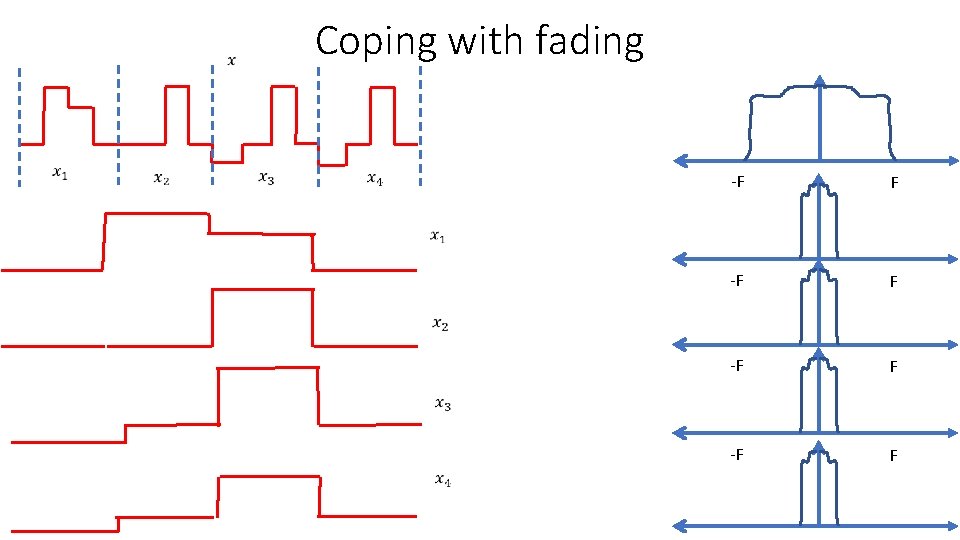
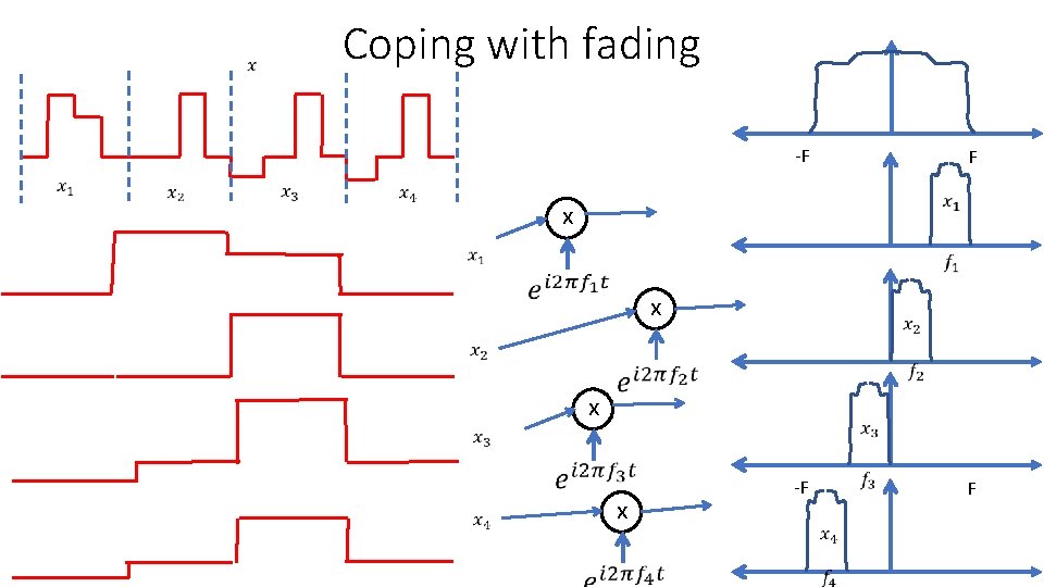
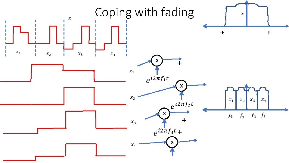
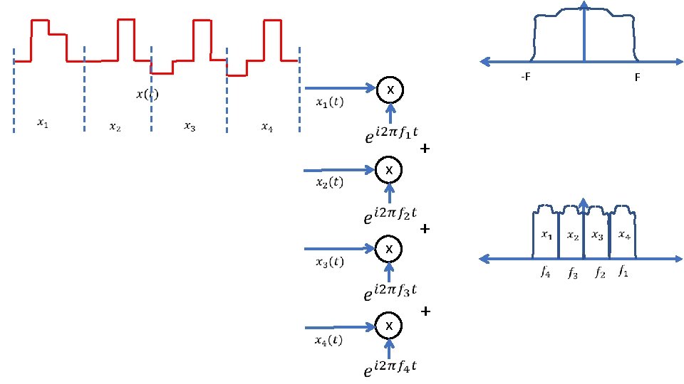
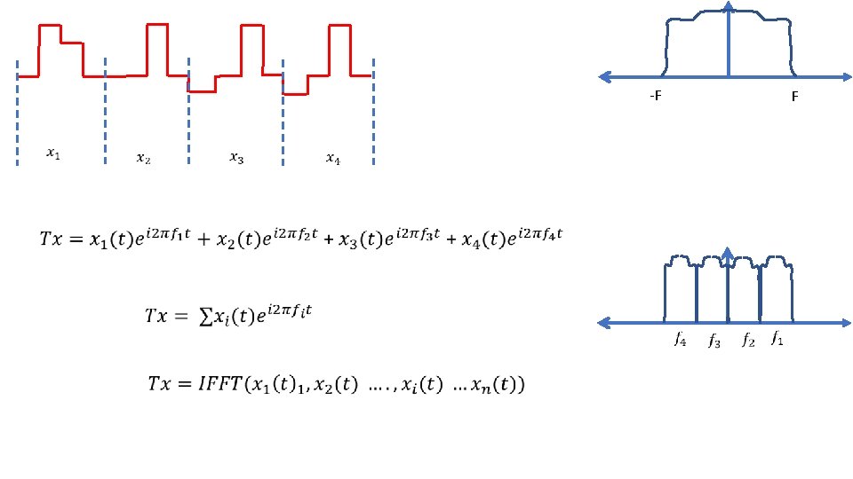
Coping with fading • Decrease bandwidth so that data frequencies do not overlap with fading frequencies • This helped eliminate the effect of fading • Disadvantage: This would waste a lot of available bandwidth • Can we do better to achieve throughput proportional to the channel quality, without wasting any bandwidth
Coping with fading -F F
Coping with fading -F F x x -F F
Coping with fading -F x + x x F x + +
-F
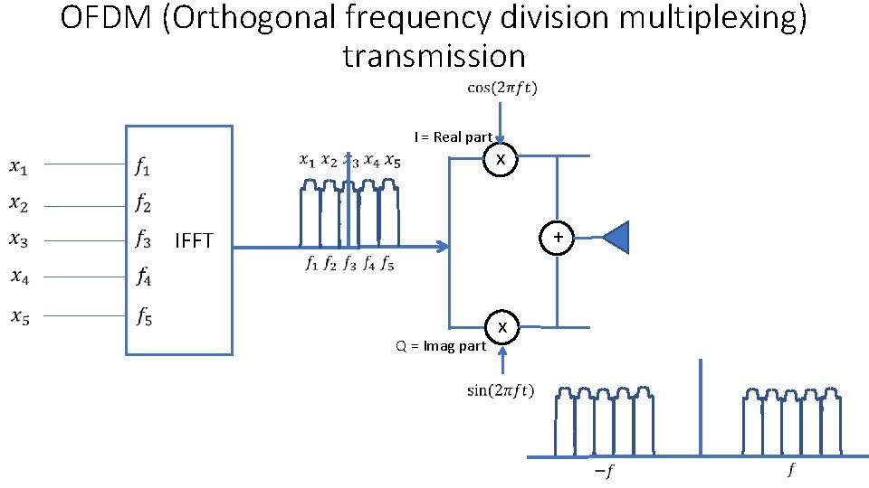
OFDM (Orthogonal frequency division multiplexing) transmission IFFT I = Real part x + Q = Imag part x
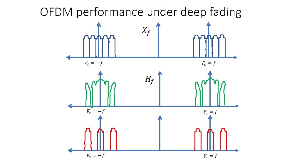
OFDM performance under deep fading
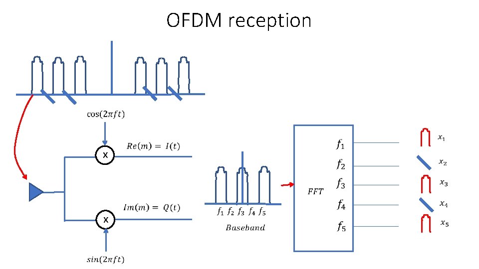
OFDM reception x x
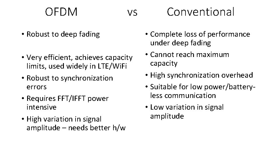
OFDM vs • Robust to deep fading • Very efficient, achieves capacity limits, used widely in LTE/Wi. Fi • Robust to synchronization errors • Requires FFT/IFFT power intensive • High variation in signal amplitude – needs better h/w Conventional • Complete loss of performance under deep fading • Cannot reach maximum capacity • High synchronization overhead • Suitable for low power/batteryless communication • Low variation in signal amplitude