MODIS Aqua PSF Point Spread Function Gerhard Meister
 Gerhard Meister, OBPG NASA Goddard Space Flight Center")

 = Sij PSF(i- i 0, j- j")
: smaller slit, 1 pixel from either")


")


- Slides: 18
MODIS Aqua PSF (Point Spread Function) Gerhard Meister, OBPG NASA Goddard Space Flight Center (Futuretech Corp. ) January 4, 2006
Background • Ocean color remote sensing imposes very stringent requirements on radiometric accuracy of bands relative to each other. • Stray light effects are very large for bright clouds next to dark ocean water. • Theoretical solution: correction with point-spread function (PSF). • Problems: PSF not well characterized, light source intensity sometimes unknown, computationally very expensive.
PSF definition: Lm (i 0, j 0) = Sij PSF(i- i 0, j- j 0)*LT(i, j) Lm = Measured radiance LT = True radiance PSF = Point Spread Function i = line index j = column index PSF kernel 25 x 25: i= i 0 -12, i 0 -11, . . . , i 0+11, i 0+12 j= j 0 -12, j 0 -11, . . . , j 0+11, j 0+12
Available from SBRS: • LSF (Line Spread Functions): smaller slit, 1 pixel from either side of slit, dynamic range 1 -10 -3, scan and (simulated) track direction • NFR (Near Field Response) measurements: scans of 1 x 10 slit (slit in track direction), up to 100 pixels to either side of peak, dynamic range 1 -10 -7 • NFR modeling: scatter model, certain shape parameters, no absolute scale for PSF
Creation of PSF: Assume that PSF of adjacent pixel in scan direction is given by 0. 125/0. 75 (theoretical value from Geolocation ATBD) of center value, adjacent pixel in track direction is 5% (from LSF) Adjust center value and scale parameter from SBRS model (Harvey-Shack) so that NFR measurements are reproduced
NFR measurements and model: Band 11
NFR measurements and model: All bands
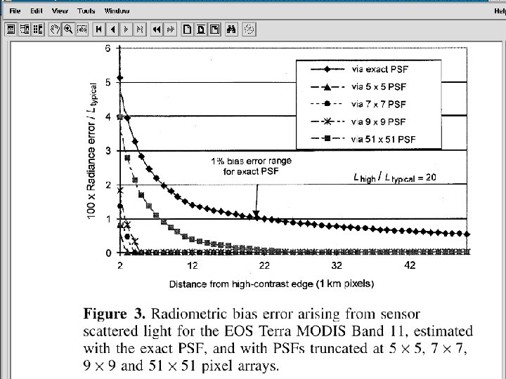
Paper by Qiu et al. on Terra PSF:
Aqua and Terra: Band 11 with Lcloud/Ltypical=20
Aqua: all bands with Lcloud/Ltypical=20 (PSF size: 512 x 512)
Aqua: all bands with Lcloud/Ltypical from 10 -40
Same as before, but 10 x 10 pixel cloud
10 x 10 pixel cloud, band 11 only, different PSF sizes
100 x 100 pixel cloud, band 11 only
Summary • Created Aqua PSF based on SBRS model and NFR measurements • For huge clouds, TOA radiances 50 pixels away from cloud will be contaminated up to 1% (even after correcting with 101 x 101 PSF) • For 100 x 100 clouds, radiances will be up to 0. 5% too high after correction with 25 x 25 PSF (0. 2% for 51 x 51) • For small clouds, radiances can be adequately corrected with 25 x 25 PSF as close as 2 pixels to the cloud
Outlook: • Still need to check the model in track direction • Refinement needed for adjacent pixel • Validate with real data (n. Lw should ‘look better’, but more noise is expected) • If successful, implement into Sea. DAS as an option • Work with MCST on Terra PSF derivation/validation
Backup slides: