
Modelling the Corrosion of Spent Nuclear Fuel Inside



- Slides: 43
Modelling the Corrosion of Spent Nuclear Fuel Inside a Failed Waste Container Nazhen Liu, Ziyan Zhu, Linda Wu, Zack Qin, David Shoesmith Department of Chemistry and Surface Science Western The University of Western Ontario London, ON, Canada This project is funded under a Collaborative Research and Development agreement between NSERC and the Nuclear Waste Management Organization
OUTLINE • Canadian disposal scenario • Redox conditions inside a failed nuclear waste container • A few key fuel properties • A one dimensional model for fuel corrosion • The need for a two dimensional model • The influence of H 2 from alpha radiolysis and steel corrosion • How much H 2 is required to completely suppress fuel corrosion? • Can the model be validated ? 2
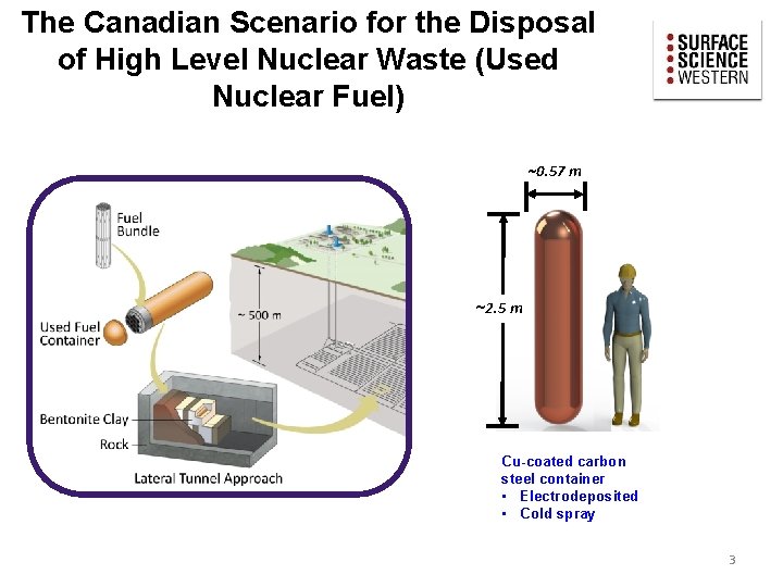
The Canadian Scenario for the Disposal of High Level Nuclear Waste (Used Nuclear Fuel) ~0. 57 m ~2. 5 m Cu-coated carbon steel container • Electrodeposited • Cold spray 3
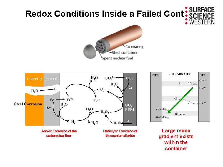
Redox Conditions Inside a Failed Container Large redox gradient exists within the container
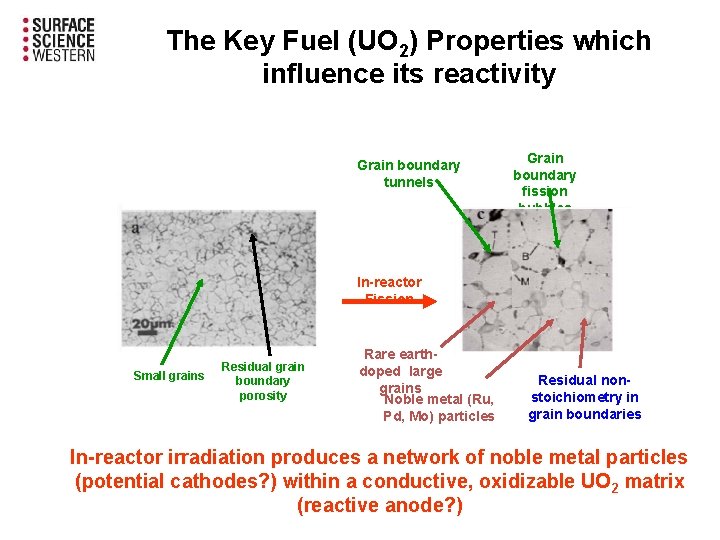
The Key Fuel (UO 2) Properties which influence its reactivity Grain boundary tunnels Grain boundary fission bubbles In-reactor Fission Small grains Residual grain boundary porosity Rare earthdoped large grains Noble metal (Ru, Pd, Mo) particles Residual nonstoichiometry in grain boundaries In-reactor irradiation produces a network of noble metal particles (potential cathodes? ) within a conductive, oxidizable UO 2 matrix (reactive anode? )
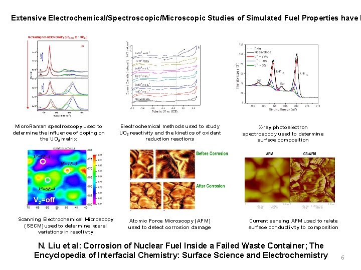
Extensive Electrochemical/Spectroscopic/Microscopic Studies of Simulated Fuel Properties have b Micro. Raman spectroscopy used to determine the influence of doping on the UO 2 matrix Scanning Electrochemical Microscopy (SECM) used to determine lateral variations in reactivity Electrochemical methods used to study UO 2 reactivity and the kinetics of oxidant reduction reactions Atomic Force Microscopy (AFM) used to detect corrosion damage X-ray photoelectron spectroscopy used to determine surface composition Current sensing AFM used to relate surface conductivity to composition N. Liu et al: Corrosion of Nuclear Fuel Inside a Failed Waste Container; The Encyclopedia of Interfacial Chemistry: Surface Science and Electrochemistry 6
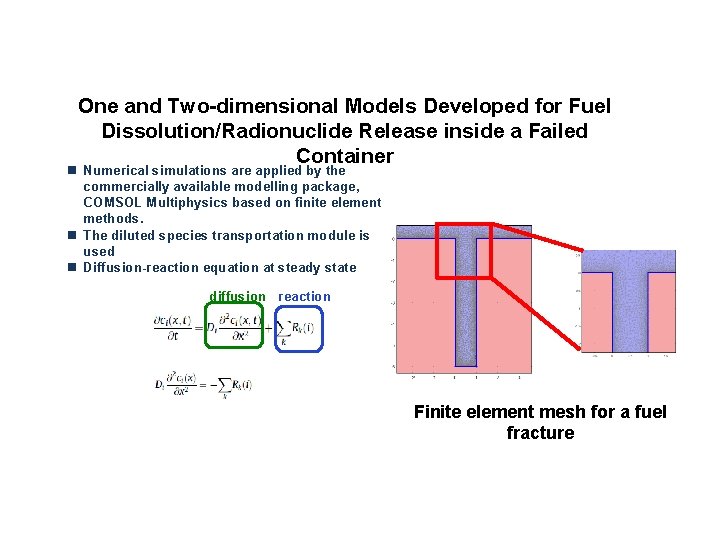
One and Two-dimensional Models Developed for Fuel Dissolution/Radionuclide Release inside a Failed Container n Numerical simulations are applied by the commercially available modelling package, COMSOL Multiphysics based on finite element methods. n The diluted species transportation module is used n Diffusion-reaction equation at steady state diffusion reaction Finite element mesh for a fuel fracture
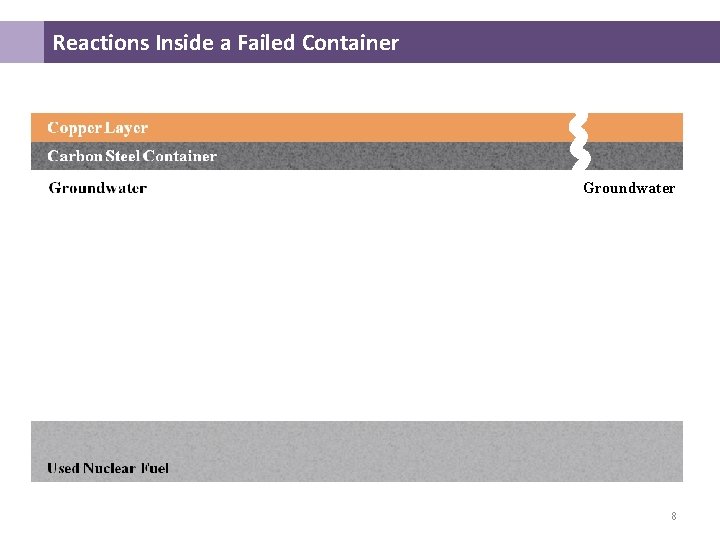
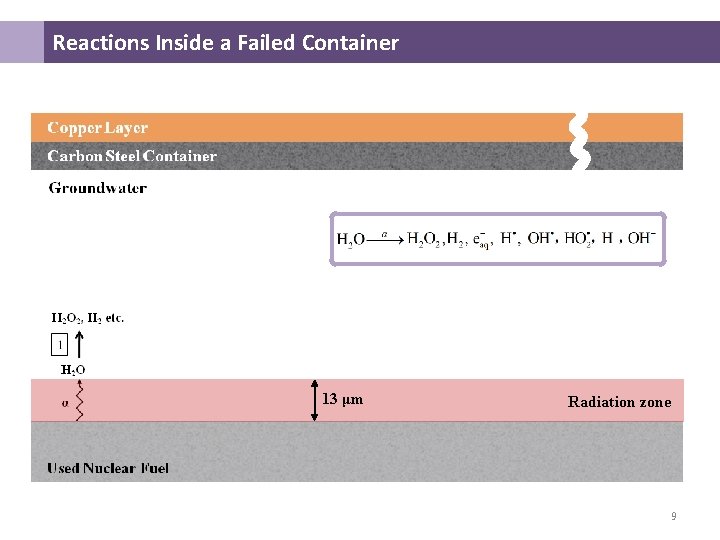
Reactions Inside a Failed Container Groundwater 8
Reactions Inside a Failed Container 13 μm Radiation zone 9
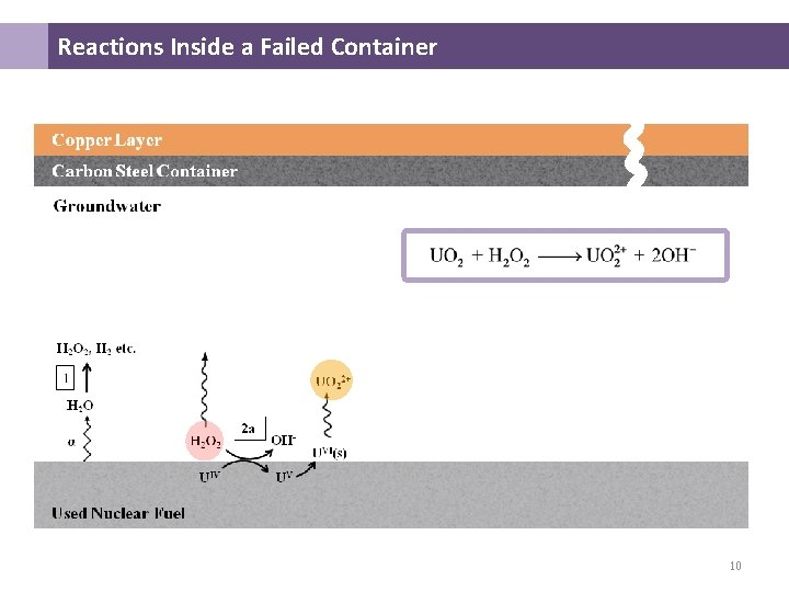
Reactions Inside a Failed Container 10
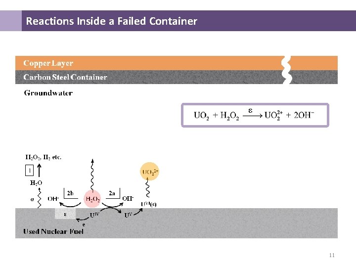
Reactions Inside a Failed Container ε 11
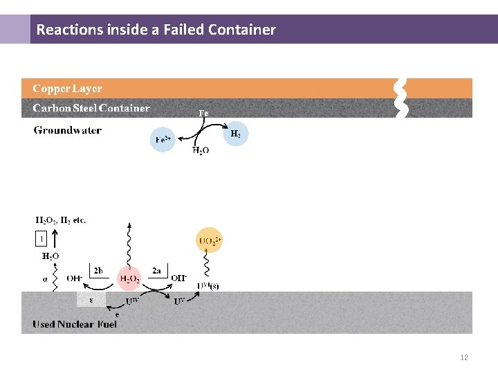
Reactions inside a Failed Container 12
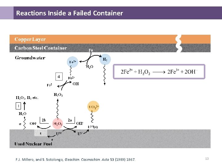
Reactions Inside a Failed Container 4 F. J. Millero, and S. Sotolongo, Geochim. Cosmochim. Acta 53 (1989) 1867. 13
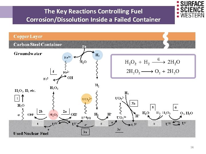
The Key Reactions Controlling Fuel Corrosion/Dissolution Inside a Failed Container 14
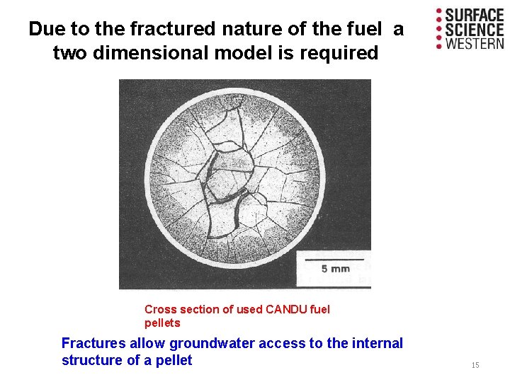
Due to the fractured nature of the fuel a two dimensional model is required Cross section of used CANDU fuel pellets Fractures allow groundwater access to the internal structure of a pellet 15
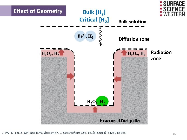
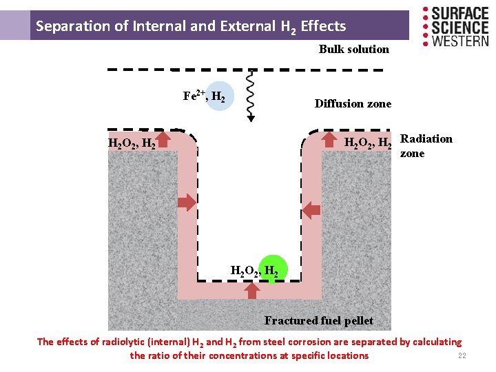
Effect of Geometry Bulk [H 2] Critical [H 2] Fe 2+, H 2 Bulk solution Diffusion zone H 2 O 2 , H 2 Radiation zone H 2 O 2 , H 2 Fractured fuel pellet L. Wu, N. Liu, Z. Qin, and D. W. Shoesmith, J. Electrochem. Soc. 161(8) (2014) E 3259 -E 3266. 16
THE INFLUENCE OF HYDROGEN ON THE FUEL CORROSION PROCESS
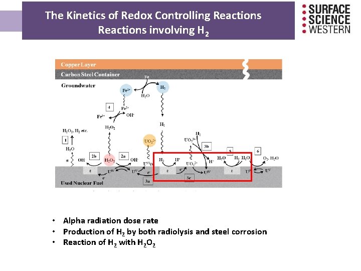
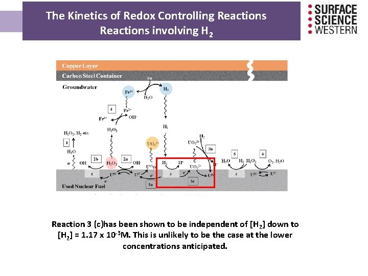
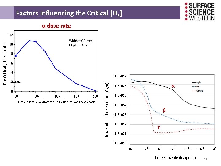
The Kinetics of Redox Controlling Reactions involving H 2 • Alpha radiation dose rate • Production of H 2 by both radiolysis and steel corrosion • Reaction of H 2 with H 2 O 2
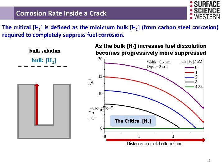
Corrosion Rate Inside a Crack The critical [H 2] is defined as the minimum bulk [H 2] (from carbon steel corrosion) required to completely suppress fuel corrosion. bulk solution As the bulk [H 2] increases fuel dissolution becomes progressively more suppressed bulk [H 2] The Critical [H 2] 19
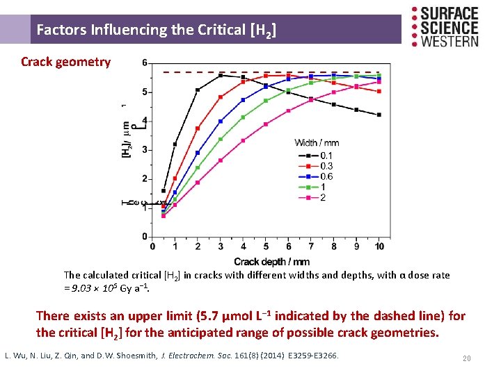
Factors Influencing the Critical [H 2] Crack geometry The calculated critical [H 2] in cracks with different widths and depths, with α dose rate = 9. 03 × 105 Gy a− 1. There exists an upper limit (5. 7 μmol L− 1 indicated by the dashed line) for the critical [H 2] for the anticipated range of possible crack geometries. L. Wu, N. Liu, Z. Qin, and D. W. Shoesmith, J. Electrochem. Soc. 161(8) (2014) E 3259 -E 3266. 20
Separation of Internal and External H 2 Effects 21
Separation of Internal and External H 2 Effects Bulk solution Fe 2+, H 2 Diffusion zone H 2 O 2, H 2 Radiation zone H 2 O 2 , H 2 Fractured fuel pellet The effects of radiolytic (internal) H 2 and H 2 from steel corrosion are separated by calculating 22 the ratio of their concentrations at specific locations
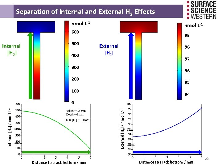
Separation of Internal and External H 2 Effects nmol L-1 600 Internal [H 2] 500 400 99 External [H 2] 98 97 300 96 200 95 100 94 External [H 2] / nmol L-1 Internal [H 2] / nmol L-1 0 Distance to crack bottom / mm 23
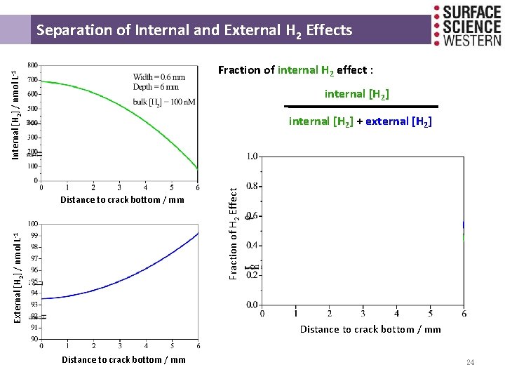
Separation of Internal and External H 2 Effects Internal [H 2] / nmol L-1 Fraction of internal H 2 effect : internal [H 2] External [H 2] / nmol L-1 Distance to crack bottom / mm Fraction of H 2 Effect internal [H 2] + external [H 2] Distance to crack bottom / mm 24
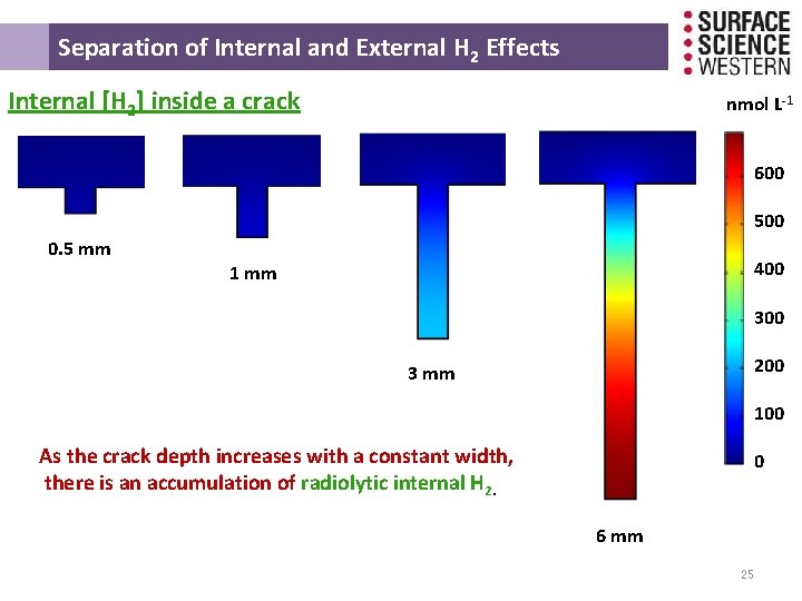
Separation of Internal and External H 2 Effects Internal [H 2] inside a crack nmol L-1 600 500 0. 5 mm 400 1 mm 300 200 3 mm 100 As the crack depth increases with a constant width, there is an accumulation of radiolytic internal H 2. 0 6 mm 25
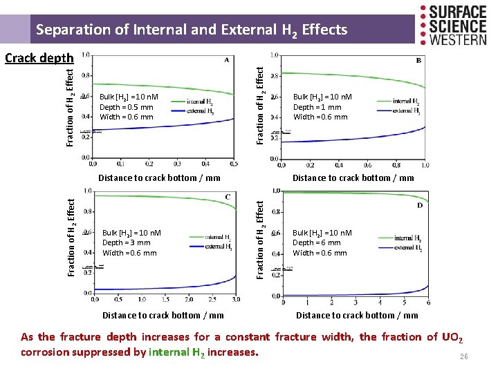
Separation of Internal and External H 2 Effects Bulk [H 2] = 10 n. M Depth = 0. 5 mm Width = 0. 6 mm Fraction of H 2 Effect Crack depth Bulk [H 2] = 10 n. M Depth = 3 mm Width = 0. 6 mm Distance to crack bottom / mm Fraction of H 2 Effect Distance to crack bottom / mm Bulk [H 2] = 10 n. M Depth = 1 mm Width = 0. 6 mm Bulk [H 2] = 10 n. M Depth = 6 mm Width = 0. 6 mm Distance to crack bottom / mm As the fracture depth increases for a constant fracture width, the fraction of UO 2 corrosion suppressed by internal H 2 increases. 26
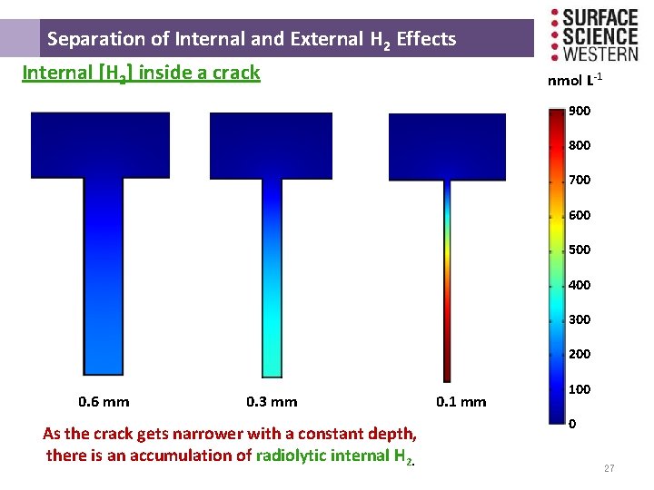
Separation of Internal and External H 2 Effects Internal [H 2] inside a crack nmol L-1 900 800 700 600 500 400 300 200 0. 6 mm 0. 3 mm As the crack gets narrower with a constant depth, there is an accumulation of radiolytic internal H 2. 0. 1 mm 100 0 27
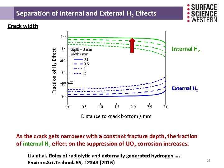
Separation of Internal and External H 2 Effects Crack width Fraction of H 2 Effect Internal H 2 External H 2 Distance to crack bottom / mm As the crack gets narrower with a constant fracture depth, the fraction of internal H 2 effect on the suppression of UO 2 corrosion increases. Liu et al. Roles of radiolytic and externally generated hydrogen …. Environ. Sci. Technol. 59, 12348 (2016) 28
Can this Model be Validated by Comparison to Corrosion Rates Measured on Fuel Specimens?
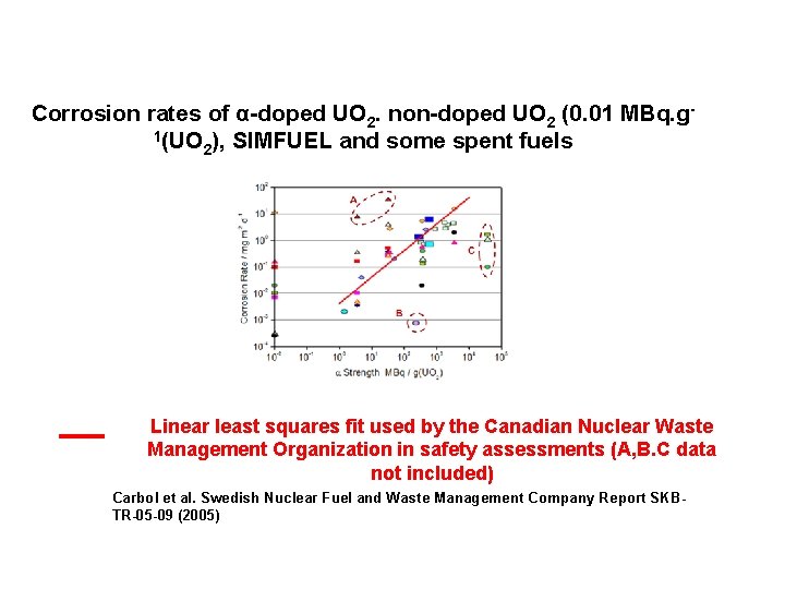
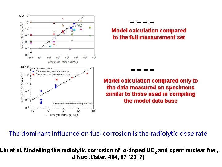
Corrosion rates of α-doped UO 2. non-doped UO 2 (0. 01 MBq. g 1(UO ), SIMFUEL and some spent fuels 2 Linear least squares fit used by the Canadian Nuclear Waste Management Organization in safety assessments (A, B. C data not included) Carbol et al. Swedish Nuclear Fuel and Waste Management Company Report SKBTR-05 -09 (2005)
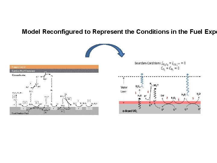
Model Reconfigured to Represent the Conditions in the Fuel Expe
Model calculation compared to the full measurement set Model calculation compared only to the data measured on specimens similar to those used in compiling the model data base The dominant influence on fuel corrosion is the radiolytic dose rate Liu et al. Modelling the radiolytic corrosion of α-doped UO 2 and spent nuclear fuel, J. Nucl. Mater, 494, 87 (2017)
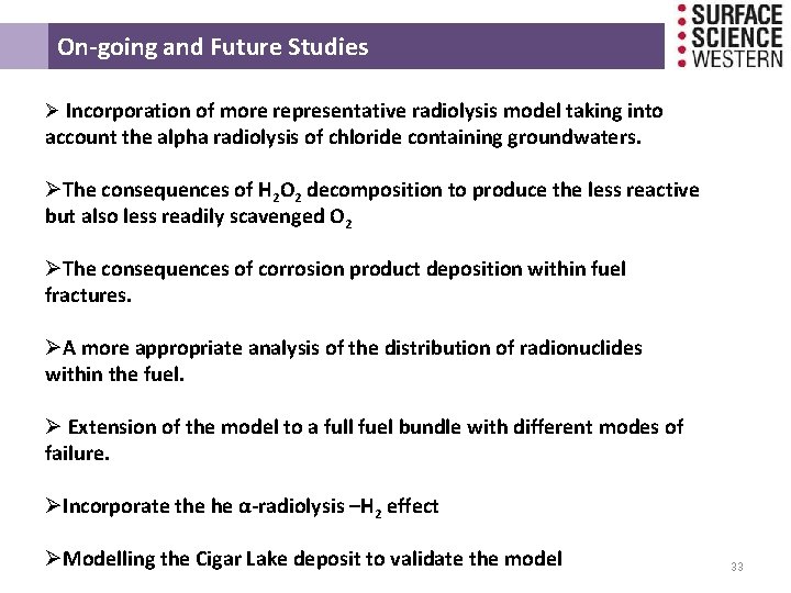
On-going and Future Studies Ø Incorporation of more representative radiolysis model taking into account the alpha radiolysis of chloride containing groundwaters. ØThe consequences of H 2 O 2 decomposition to produce the less reactive but also less readily scavenged O 2 ØThe consequences of corrosion product deposition within fuel fractures. ØA more appropriate analysis of the distribution of radionuclides within the fuel. Ø Extension of the model to a full fuel bundle with different modes of failure. ØIncorporate the he α-radiolysis –H 2 effect ØModelling the Cigar Lake deposit to validate the model 33
Acknowledgements Zach Qin Nazhe n Liu Nazhen Liu Zach Qin Michae l Wu Ziyan Zhu This research is funded under the Industrial Research Chair agreement between the Canadian Natural Sciences and Engineering Research Council (NSERC) and NWMO (Nuclear Waste Management Organization), Canada. 34
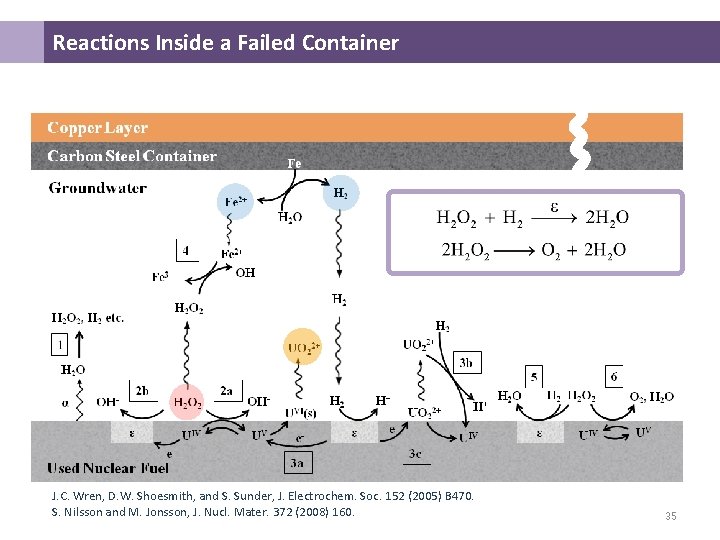
Reactions Inside a Failed Container J. C. Wren, D. W. Shoesmith, and S. Sunder, J. Electrochem. Soc. 152 (2005) B 470. S. Nilsson and M. Jonsson, J. Nucl. Mater. 372 (2008) 160. 35
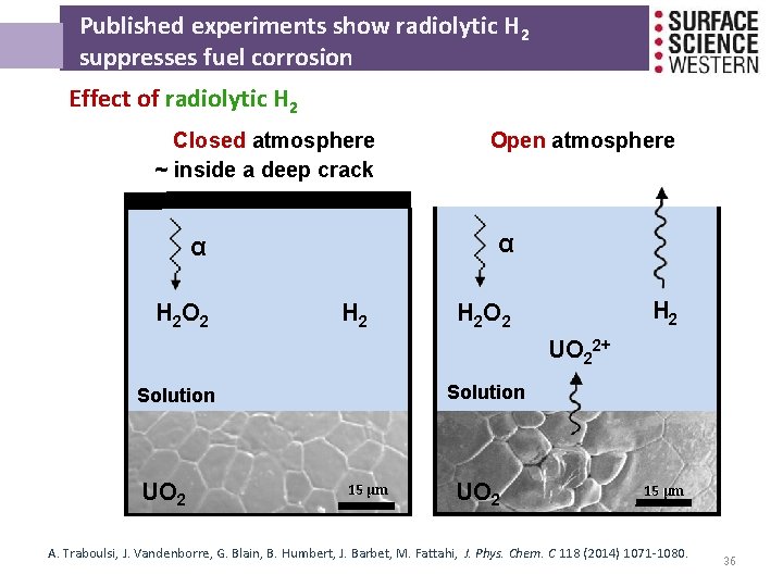
Published experiments show radiolytic H 2 suppresses fuel corrosion Effect of radiolytic H 2 Closed atmosphere ~ inside a deep crack α α H 2 O 2 Open atmosphere H 2 H 2 O 2 UO 22+ Solution UO 2 15 μm A. Traboulsi, J. Vandenborre, G. Blain, B. Humbert, J. Barbet, M. Fattahi, J. Phys. Chem. C 118 (2014) 1071 -1080. 36
The Kinetics of Redox Controlling Reactions involving H 2 Reaction 3 (c)has been shown to be independent of [H 2] down to [H 2] = 1. 17 x 10 -3 M. This is unlikely to be the case at the lower concentrations anticipated.
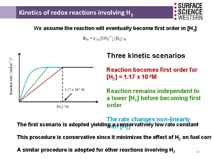
Kinetics of redox reactions involving H 2 We assume the reaction will eventually become first order in [H ] 2 Three kinetic scenarios Reaction becomes first order for [H 2] < 1. 17 x 10 -6 M Reaction remains independent to a lower [H 2] before becoming first order The rate changes non-linearly The first scenario is adopted yielding a conservatively low rate constant with [H 2] This procedure is conservative since it minimizes the effect of H 2 on fuel corro A similar procedure is adopted for other reactions involving H 2 38
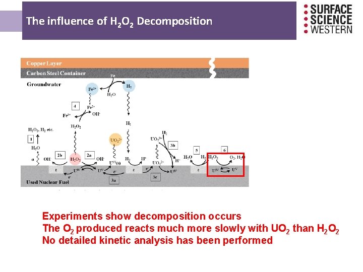
The influence of H 2 O 2 Decomposition Experiments show decomposition occurs The O 2 produced reacts much more slowly with UO 2 than H 2 O 2 No detailed kinetic analysis has been performed
Factors Influencing the Critical [H 2] The Critical [H 2] / μmol L-1 α dose rate 10 102 103 104 105 Time since emplacement in the repository / year Dose rate at fuel surface (Gy/a) 1 E +07 α 1 E +06 1 E +05 1 E +04 β 1 E +03 1 E +02 ϒ 1 E +01 1 E +00 10 2 10 3 10 4 10 5 10 6 10 7 Time since discharge (a) 40
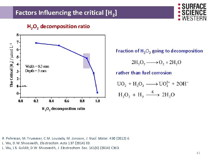
Factors Influencing the critical [H 2] The Critical [H 2] / μmol L-1 H 2 O 2 decomposition ratio Fraction of H 2 O 2 going to decomposition rather than fuel corrosion H 2 O 2 decomposition ratio R. Pehrman, M. Trummer, C. M. Lousada, M. Jonsson, J. Nucl. Mater. 430 (2012) 6. L. Wu, D. W. Shoesmith, Electrochim. Acta 137 (2014) 83. L. Wu, J. S. Goldik, D. W. Shoesmith, J. Electrochem. Soc. 161(6) (2014) C 363. 41
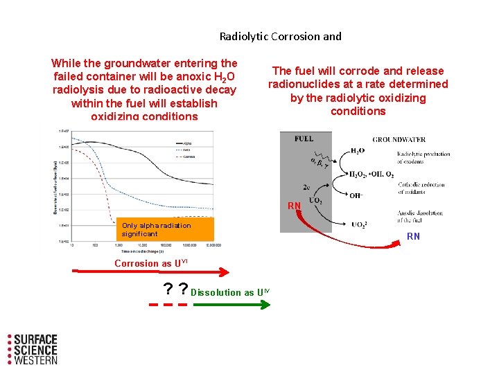
Radiolytic Corrosion and While the groundwater entering the failed container will be anoxic H 2 O radiolysis due to radioactive decay within the fuel will establish oxidizing conditions The fuel will corrode and release radionuclides at a rate determined by the radiolytic oxidizing conditions RN Only alpha radiation significant RN Corrosion as UVI ? ? Dissolution as U IV
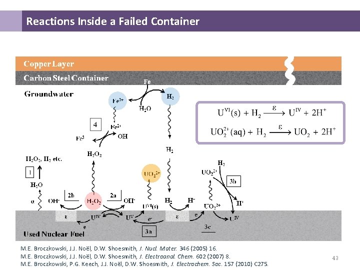
Reactions Inside a Failed Container 4 M. E. Broczkowski, J. J. Noël, D. W. Shoesmith, J. Nucl. Mater. 346 (2005) 16. M. E. Broczkowski, J. J. Noël, D. W. Shoesmith, J. Electroanal. Chem. 602 (2007) 8. M. E. Broczkowski, P. G. Keech, J. J. Noël, D. W. Shoesmith, J. Electrochem. Soc. 157 (2010) C 275. 43