
Modeling of the Effects of Beam Fluctuations from

Modeling of the Effects of Beam Fluctuations from LIGO’s Input Optics Nafis Jamal Shivanand Sanichiro Yoshida Biplab Bhawal LSC Conference Aug ’ 05 LIGO-G 050443 -00 -Z Nafis Jamal, SURF ‘ 05
PART I: Modeling MMT’s motion and effect on power in the arm cavity Nafis Jamal, SURF ‘ 05
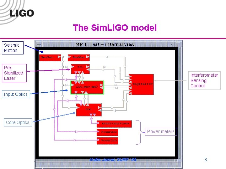
The Sim. LIGO model Seismic Motion Pre. Stabilized Laser Interferometer Sensing Control Input Optics Core Optics Power meters Nafis Jamal, SURF ‘ 05 3
Objective q Study the effect of the fluctuation of the input beam § Provide seismic noise to input optics § No seismic influence on core optics § Study the effect of input beam’s fluctuations under the following conditions: Nafis Jamal, SURF ‘ 05 4
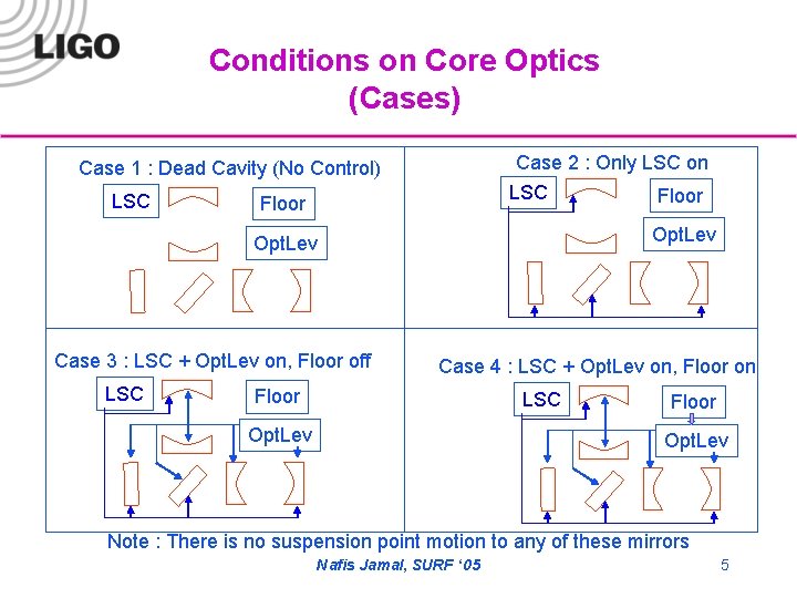
Conditions on Core Optics (Cases) Case 2 : Only LSC on Case 1 : Dead Cavity (No Control) LSC Floor Opt. Lev Case 3 : LSC + Opt. Lev on, Floor off LSC Floor Case 4 : LSC + Opt. Lev on, Floor on Floor LSC Opt. Lev Floor Opt. Lev Note : There is no suspension point motion to any of these mirrors Nafis Jamal, SURF ‘ 05 5
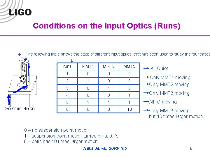
Conditions on the Input Optics (Runs) u The following table shows the state of different input optics, that has been used to study the four cases Seismic Noise runs MMT 1 MMT 2 MMT 3 1 0 0 0 2 1 0 0 3 0 1 0 4 0 0 1 Only MMT 3 moving 5 1 1 1 All IO moving 6 0 0 10 Only MMT 3 moving but 10 times larger motion All Quiet Only MMT 1 moving Only MMT 2 moving 0 – no suspension point motion 1 – suspension point motion turned on at 0. 7 s 10 – optic has 10 times larger motion Nafis Jamal, SURF ‘ 05 6
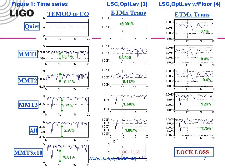
Figure 1: Time series TEMOO to CO MMT 2 MMT 3 All MMT 3 x 10 ETMx Trans LSC, Opt. Lev w/Floor (4) ETMx Trans <0. 001% Quiet MMT 1 LSC, Opt. Lev (3) 0. 4% 0. 04% 0. 10% 1. 56% 2. 20% 0. 045% 0. 112% 0. 4% 1. 340% 1. 24% 1. 887% Lock loss 78. 81% 0. 4% Nafis Jamal, SURF ‘ 05 1. 75% LOCK LOSS 7
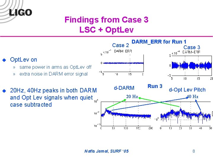
Findings from Case 3 LSC + Opt. Lev Case 2 u DARM_ERR for Run 1 Case 3 Opt. Lev on » same power in arms as Opt. Lev off » extra noise in DARM error signal u 20 Hz, 40 Hz peaks in both DARM and Opt Lev signals when quiet case subtracted d-DARM 20 Hz Nafis Jamal, SURF ‘ 05 Run 3 d-Opt Lev Pitch 40 Hz 8
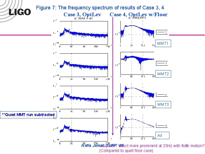
Figure 7: The frequency spectrum of results of Case 3, 4 Case 3, Opt. Lev Case 4, Opt. Lev w/Floor MMT 1 MMT 2 MMT 3 **Quiet MMT run subtracted All Nafis Jamal, 9 motion? Why. SURF MMT ‘ 05 effect more prominent at 23 Hz with floor (Compared to quiet floor case)
Conclusion (Part I) u u When MMT 3 experiences 10 times larger suspension point motion, the fluctuation in the input beam increases by about 77% and the LSC fails to keep the arm cavities locked. Even when LSC works at its best, the maximum mode mismatch due to the input beam fluctuation is directly proportional to the fluctuations in the TEM 00 mode from MMT. A different mechanism is needed to correct this (ASC control to MMT 3). Nafis Jamal, SURF ‘ 05 10
PART II: Modeling LIGO’s Input Mode Cleaner (MC) Nafis Jamal, SURF ‘ 05
Objectives 1. Create a complete, dynamic model of LIGO’s input mode cleaner. 2. Incorporate this model into Sim. LIGO and study the how the mode cleaner’s performance affects LIGO’s sensitivity. Nafis Jamal, SURF ‘ 05 12
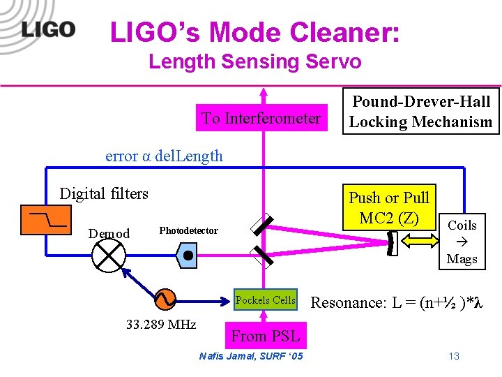
LIGO’s Mode Cleaner: Length Sensing Servo To Interferometer Pound-Drever-Hall Locking Mechanism error α del. Length Digital filters Demod Push or Pull MC 2 (Z) Photodetector Pockels Cells 33. 289 MHz Coils Mags Resonance: L = (n+½ )*λ From PSL Nafis Jamal, SURF ‘ 05 13
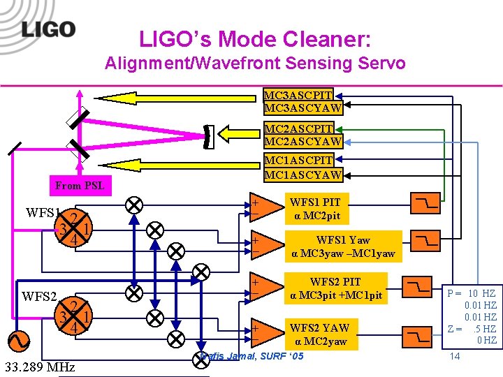
LIGO’s Mode Cleaner: Alignment/Wavefront Sensing Servo MC 3 ASCPIT MC 3 ASCYAW MC 2 ASCPIT MC 2 ASCYAW MC 1 ASCPIT MC 1 ASCYAW From PSL WFS 1 2 3 1 4 WFS 2 2 3 1 4 33. 289 MHz + _ WFS 1 PIT α MC 2 pit + _ WFS 1 Yaw α MC 3 yaw –MC 1 yaw + _ WFS 2 PIT α MC 3 pit +MC 1 pit + _ WFS 2 YAW α MC 2 yaw Nafis Jamal, SURF ‘ 05 P = 10 HZ 0. 01 HZ Z =. 5 HZ 0 HZ 14
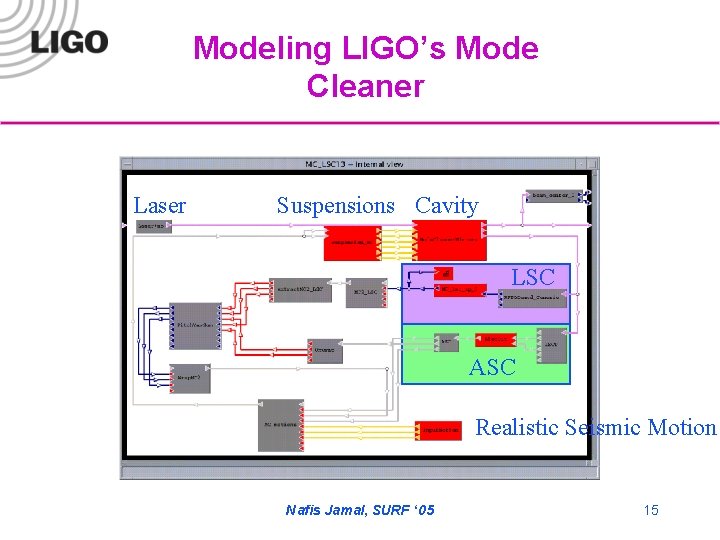
Modeling LIGO’s Mode Cleaner Laser Suspensions Cavity LSC ASC Realistic Seismic Motion Nafis Jamal, SURF ‘ 05 15
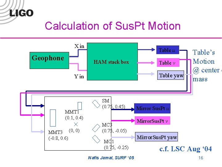
Calculation of Sus. Pt Motion X in Geophone Table u HAM stack box Table yaw Y in MMT 1 (0. 1, 0. 4) MMT 3 (0, 0) (-0. 8, 0. 6) Table v SM (0. 75, 0. 45) MC 3 (0. 75, -0. 05) MC 1 (0. 75, -0. 25) Nafis Jamal, SURF ‘ 05 Table’s Motion @ center o mass Mirror Sus. Pt u Mirror. Sus. Pt v Mirror. Sus. Pt yaw c. f. LSC Aug ‘ 04 16
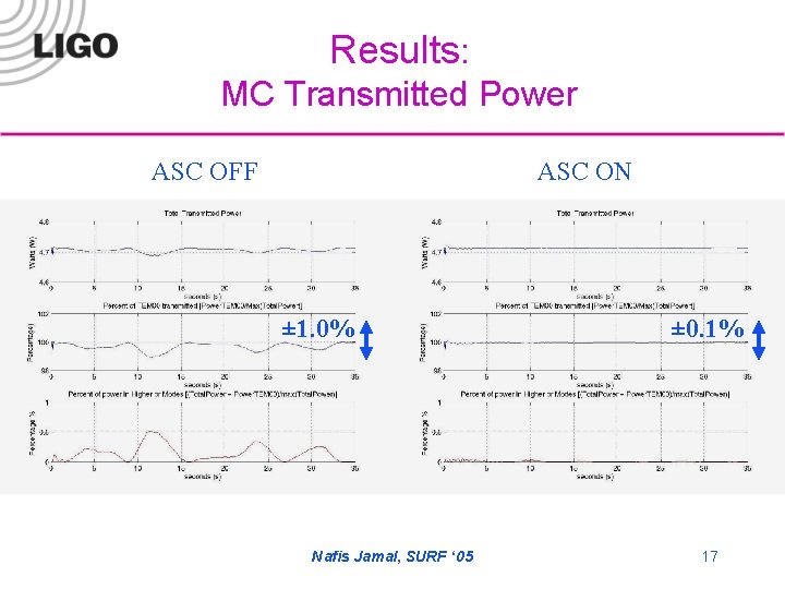
Results: MC Transmitted Power ASC OFF ASC ON ± 1. 0% Nafis Jamal, SURF ‘ 05 0. 1% ± 0. 1% 17
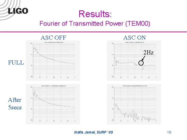
Results: Fourier of Transmitted Power (TEM 00) ASC OFF ASC ON 2 Hz FULL After 5 secs Nafis Jamal, SURF ‘ 05 18
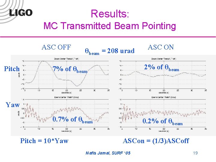
Results: MC Transmitted Beam Pointing ASC OFF Pitch θbeam = 208 urad ASC ON 7% of θbeam 2% of θbeam 0. 7% of θbeam 0. 2% of θbeam Yaw Pitch = 10*Yaw ASCon = (1/3)ASCoff Nafis Jamal, SURF ‘ 05 19
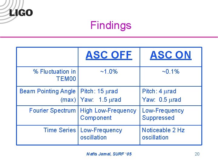
Findings % Fluctuation in TEM 00 ASC OFF ASC ON ~1. 0% ~0. 1% Beam Pointing Angle Pitch: 15 mrad (max) Yaw: 1. 5 mrad Pitch: 4 mrad Yaw: 0. 5 mrad Fourier Spectrum High Low-Frequency Component Suppressed Time Series Low-Frequency oscillation Nafis Jamal, SURF ‘ 05 Noticeable 2 Hz oscillation 20
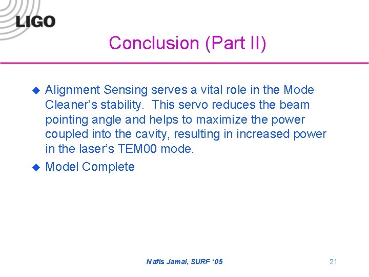
Conclusion (Part II) u u Alignment Sensing serves a vital role in the Mode Cleaner’s stability. This servo reduces the beam pointing angle and helps to maximize the power coupled into the cavity, resulting in increased power in the laser’s TEM 00 mode. Model Complete Nafis Jamal, SURF ‘ 05 21
Future Work: u u Now that the Mode Cleaner has been completely modeled, I have begun to incorporate this box in Sim. LIGO. We will study the affect of mode cleaner on the power coupled into the cavities as well as its affect on the differential arm signal. Update current model to study Advanced LIGO’s input mode cleaner Study the effect of the input beam’s fluctuations when all of the core optics receive seismic noise Activate the arm cavities’ ASC to act upon MMT 3, stabilize the input beam to the RM. Nafis Jamal, SURF ‘ 05 22
Thanks SURF! Nafis Jamal, SURF ‘ 05
- Slides: 23