
MODELING ATMOSPHERIC PRESSURE PLASMA MULTIJET DYNAMICS Amanda M
- Slides: 20
MODELING ATMOSPHERIC PRESSURE PLASMA MULTI-JET DYNAMICS* Amanda M. Lietza Xavier Damanyb, Eric Robertb, Jean -Michel Pouvesleb, and Mark J. Kushnerc a)Dept. Nuclear Engineering and Radiological Sciences University of Michigan, Ann Arbor, MI 48109, USA b) GREMI, UMR 7344 CNRS Université d’Orléans, France C)Dept. Electrical Engineering and Computer Science University of Michigan, Ann Arbor, MI 48109, USA lietz@umich. edu MIPSE Symposium 14 November 2018 * Work was supported by the DOE Office of Fusion Energy Science and the National Science Foundation.
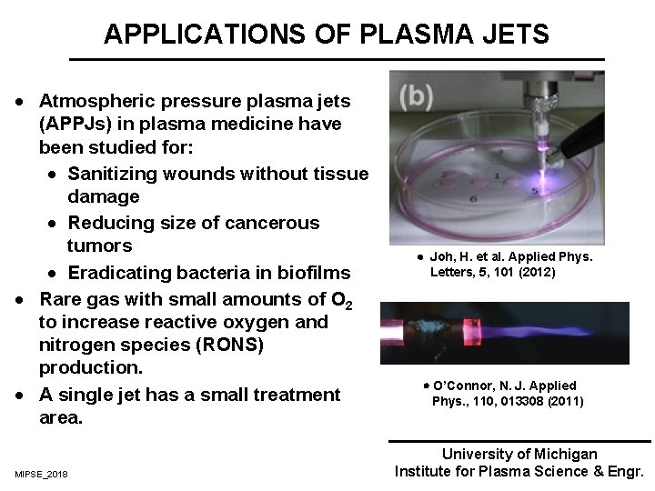
APPLICATIONS OF PLASMA JETS · Atmospheric pressure plasma jets (APPJs) in plasma medicine have been studied for: · Sanitizing wounds without tissue damage · Reducing size of cancerous tumors · Eradicating bacteria in biofilms · Rare gas with small amounts of O 2 to increase reactive oxygen and nitrogen species (RONS) production. · A single jet has a small treatment area. MIPSE_2018 Joh, H. et al. Applied Phys. Letters, 5, 101 (2012) O’Connor, N. J. Applied Phys. , 110, 013308 (2011) University of Michigan Institute for Plasma Science & Engr.
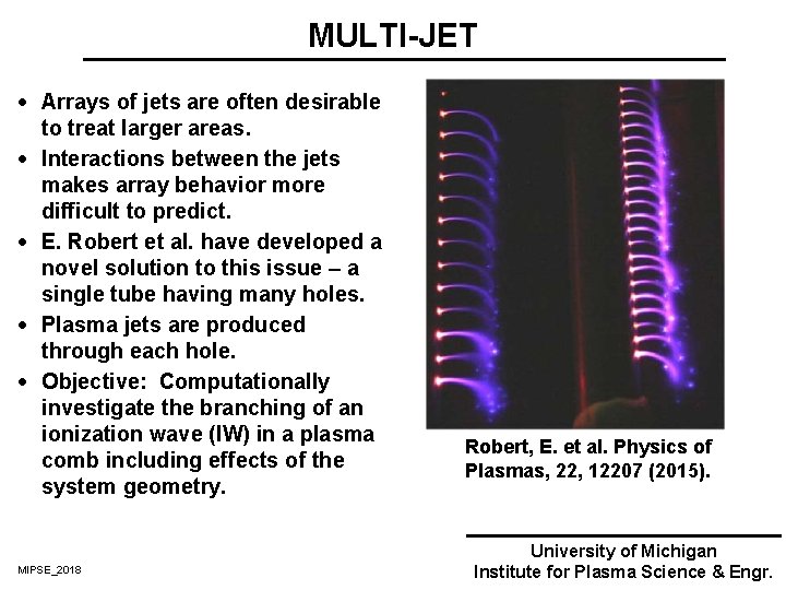
MULTI-JET · Arrays of jets are often desirable to treat larger areas. · Interactions between the jets makes array behavior more difficult to predict. · E. Robert et al. have developed a novel solution to this issue – a single tube having many holes. · Plasma jets are produced through each hole. · Objective: Computationally investigate the branching of an ionization wave (IW) in a plasma comb including effects of the system geometry. MIPSE_2018 Robert, E. et al. Physics of Plasmas, 22, 12207 (2015). University of Michigan Institute for Plasma Science & Engr.
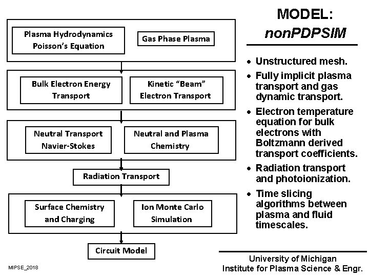
Plasma Hydrodynamics Poisson’s Equation Bulk Electron Energy Transport Neutral Transport Navier-Stokes Gas Phase Plasma Kinetic “Beam” Electron Transport Neutral and Plasma Chemistry Radiation Transport Surface Chemistry and Charging Ion Monte Carlo Simulation Circuit Model MIPSE_2018 MODEL: non. PDPSIM · Unstructured mesh. · Fully implicit plasma transport and gas dynamic transport. · Electron temperature equation for bulk electrons with Boltzmann derived transport coefficients. · Radiation transport and photoionization. · Time slicing algorithms between plasma and fluid timescales. University of Michigan Institute for Plasma Science & Engr.
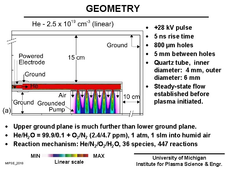
GEOMETRY · · · +28 k. V pulse 5 ns rise time 800 µm holes 5 mm between holes Quartz tube, inner diameter: 4 mm, outer diameter: 6 mm · Steady-state flow established before plasma initiated. · Upper ground plane is much further than lower ground plane. · He/H 2 O = 99. 9/0. 1 + O 2/N 2 (2. 4/4. 7 ppm), 1 atm, 1 slm into humid air · Reaction mechanism: He/N 2/O 2/H 2 O, 36 species, 447 reactions MIN MIPSE_2018 MAX Linear scale University of Michigan Institute for Plasma Science & Engr.
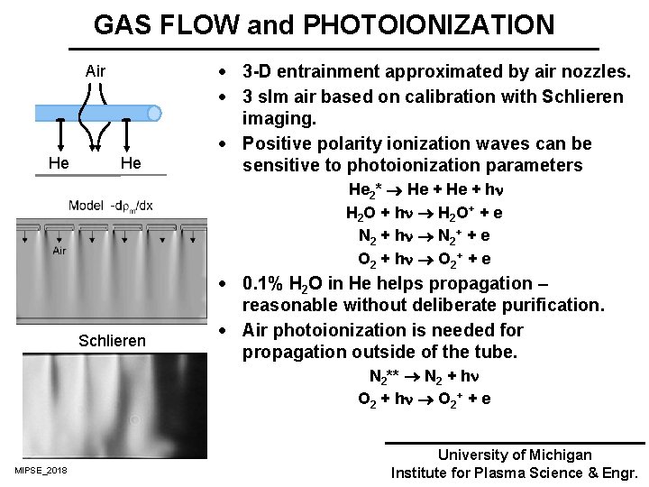
GAS FLOW and PHOTOIONIZATION Air He He · 3 -D entrainment approximated by air nozzles. · 3 slm air based on calibration with Schlieren imaging. · Positive polarity ionization waves can be sensitive to photoionization parameters He 2* He + h H 2 O + h H 2 O+ + e N 2 + h N 2+ + e O 2 + h O 2+ + e Schlieren · 0. 1% H 2 O in He helps propagation – reasonable without deliberate purification. · Air photoionization is needed for propagation outside of the tube. N 2** N 2 + h O 2 + h O 2+ + e MIPSE_2018 University of Michigan Institute for Plasma Science & Engr.
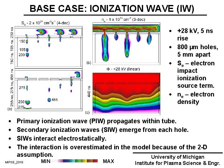
BASE CASE: IONIZATION WAVE (IW) · +28 k. V, 5 ns rise · 800 µm holes, 5 mm apart · Se – electron impact ionization source term. · ne – electron density · · Primary ionization wave (PIW) propagates within tube. Secondary ionization waves (SIW) emerge from each hole. SIWs interact electrostatically. The interaction is overestimated in the model because of the 2 -D assumption. University of Michigan MIPSE_2018 MIN MAX Institute for Plasma Science & Engr.
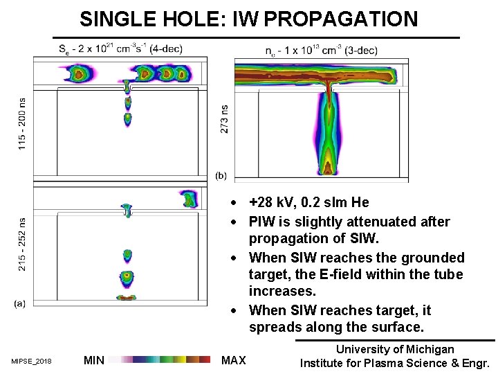
SINGLE HOLE: IW PROPAGATION · +28 k. V, 0. 2 slm He · PIW is slightly attenuated after propagation of SIW. · When SIW reaches the grounded target, the E-field within the tube increases. · When SIW reaches target, it spreads along the surface. MIPSE_2018 MIN MAX University of Michigan Institute for Plasma Science & Engr.
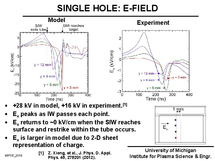
SINGLE HOLE: E-FIELD Model Experiment · +28 k. V in model, +16 k. V in experiment. [1] · Ex peaks as IW passes each point. · Ex returns to ~0 k. V/cm when the SIW reaches surface and restrike within the tube occurs. · Ex is larger in model due to 2 -D sheet representation of charge. MIPSE_2018 [1] Z. Xiong, et al. , J. Phys. D. Appl. Phys. 45, 275201 (2012). University of Michigan Institute for Plasma Science & Engr.
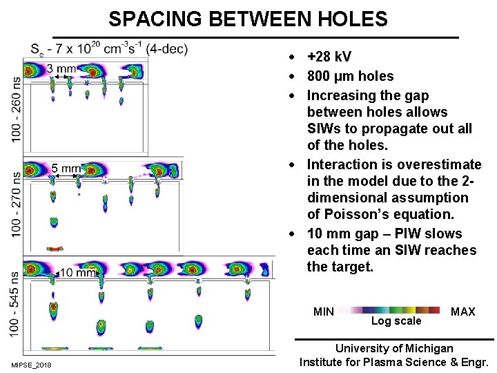
SPACING BETWEEN HOLES · +28 k. V · 800 µm holes · Increasing the gap between holes allows SIWs to propagate out all of the holes. · Interaction is overestimate in the model due to the 2 dimensional assumption of Poisson’s equation. · 10 mm gap – PIW slows each time an SIW reaches the target. MIN MIPSE_2018 Log scale MAX University of Michigan Institute for Plasma Science & Engr.
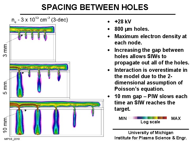
SPACING BETWEEN HOLES · +28 k. V · 800 µm holes. · Maximum electron density at each node. · Increasing the gap between holes allows SIWs to propagate out all of the holes. · Interaction is overestimate in the model due to the 2 dimensional assumption of Poisson’s equation. · 10 mm gap – PIW slows each time an SIW reaches the target. MIN MIPSE_2018 Log scale MAX University of Michigan Institute for Plasma Science & Engr.
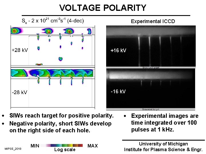
VOLTAGE POLARITY Experimental ICCD +16 k. V -16 k. V · SIWs reach target for positive polarity. · Negative polarity, short SIWs develop on the right side of each hole. MIPSE_2018 MIN Log scale MAX · Experimental images are time integrated over 100 pulses at 1 k. Hz. University of Michigan Institute for Plasma Science & Engr.
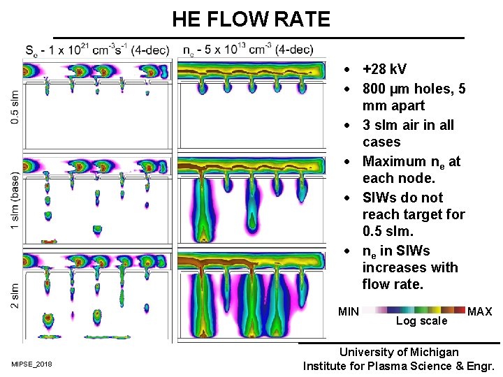
HE FLOW RATE · +28 k. V · 800 µm holes, 5 mm apart · 3 slm air in all cases · Maximum ne at each node. · SIWs do not reach target for 0. 5 slm. · ne in SIWs increases with flow rate. MIN MIPSE_2018 Log scale MAX University of Michigan Institute for Plasma Science & Engr.
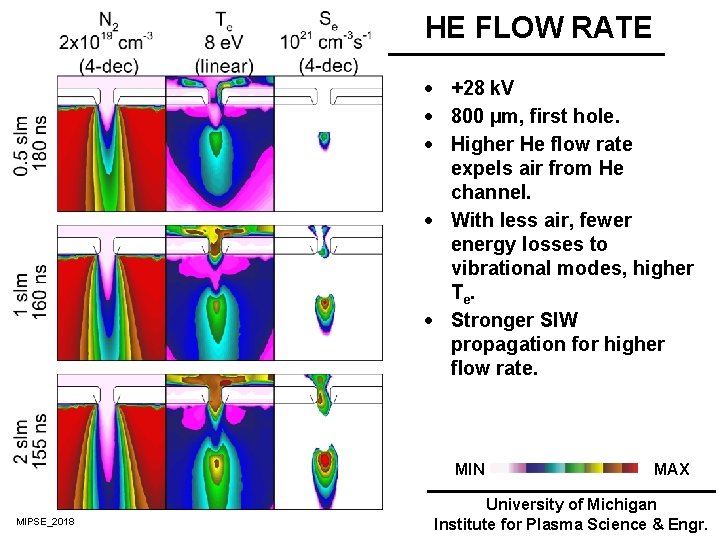
HE FLOW RATE · +28 k. V · 800 µm, first hole. · Higher He flow rate expels air from He channel. · With less air, fewer energy losses to vibrational modes, higher Te. · Stronger SIW propagation for higher flow rate. MIN MIPSE_2018 MAX University of Michigan Institute for Plasma Science & Engr.
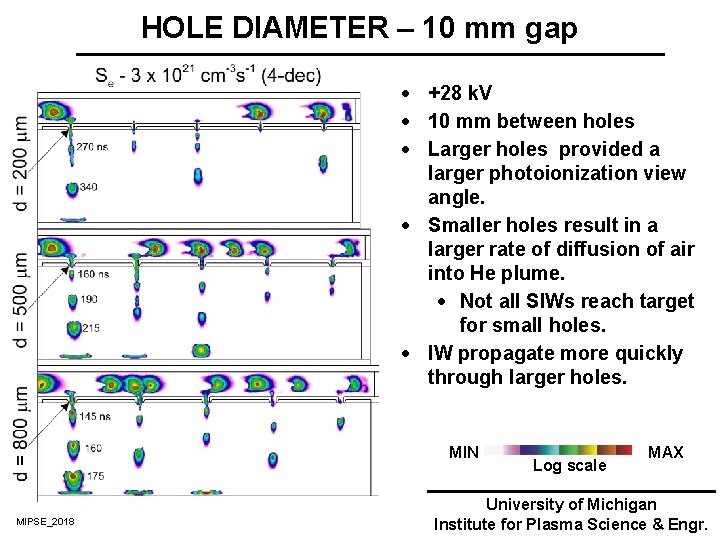
HOLE DIAMETER – 10 mm gap · +28 k. V · 10 mm between holes · Larger holes provided a larger photoionization view angle. · Smaller holes result in a larger rate of diffusion of air into He plume. · Not all SIWs reach target for small holes. · IW propagate more quickly through larger holes. MIN MIPSE_2018 Log scale MAX University of Michigan Institute for Plasma Science & Engr.
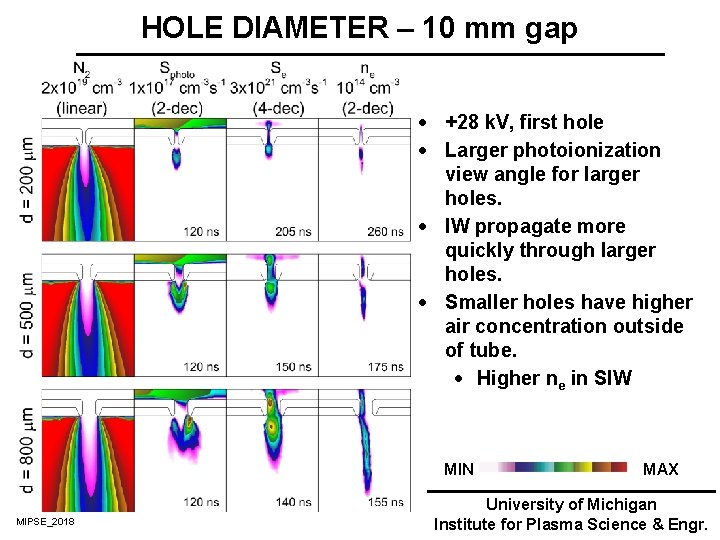
HOLE DIAMETER – 10 mm gap · +28 k. V, first hole · Larger photoionization view angle for larger holes. · IW propagate more quickly through larger holes. · Smaller holes have higher air concentration outside of tube. · Higher ne in SIW MIN MIPSE_2018 MAX University of Michigan Institute for Plasma Science & Engr.
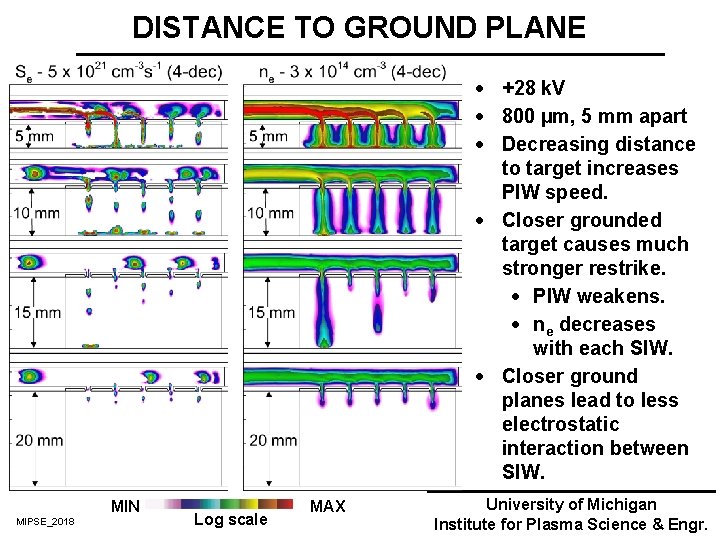
DISTANCE TO GROUND PLANE · +28 k. V · 800 µm, 5 mm apart · Decreasing distance to target increases PIW speed. · Closer grounded target causes much stronger restrike. · PIW weakens. · ne decreases with each SIW. · Closer ground planes lead to less electrostatic interaction between SIW. MIN MIPSE_2018 Log scale MAX University of Michigan Institute for Plasma Science & Engr.
CONCLUDING REMARKS · The properties of atmospheric pressure plasma multi-jets have been studied using non. PDPSIM and experimental observations. · Secondary ionization waves (SIWs) propagate out of the holes more effectively for positive polarity pulses because there is no potential drop at powered electrode. · SIWs propagate more rapidly through larger holes due to photoionization view angle. · Decreasing the distance to the grounded target is a tradeoff: · Interaction between the SIWs are less significant. · SIWs are more intense, restrikes attenuate the PIW. MIPSE_2018 University of Michigan Institute for Plasma Science & Engr.
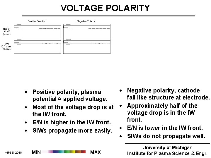
VOLTAGE POLARITY · Negative polarity, cathode · Positive polarity, plasma fall like structure at electrode. potential ≈ applied voltage. · Most of the voltage drop is at · Approximately half of the voltage drop is in the IW front. · E/N is higher in the IW front. · SIWs propagate more easily. · E/N is lower in the IW front. · SIWs do not propagate well. MIPSE_2018 MIN MAX University of Michigan Institute for Plasma Science & Engr.
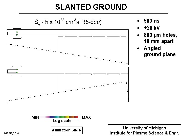
SLANTED GROUND · 500 ns · +28 k. V · 800 µm holes, 10 mm apart · Angled ground plane MIN MIPSE_2018 Log scale Animation Slide MAX University of Michigan Institute for Plasma Science & Engr.