Modeling and Simulation of System D K Chaturvedi


 of a real system. It is a")


 Effectiveness (Time) Risk Reduction (Environment, Lives) Simulation makes a real and")


, An")

, Performance characteristics")


- Slides: 35
Modeling and Simulation of System D. K. Chaturvedi Reader Faculty of Engineering Dayalbagh Educational Institute Agra
Organization • Basic concepts of system. • Introduction to modeling and simulation. • Modeling and Simulation of some real life systems: – Parachute – Aircraft Arrester barrier system – Aircraft landing control system
What is a system? • The term system is derived from the Greek word systema, which means an organized relationship among functioning units or components. • A system is defined to be a collection of entities, e. g. , people or machines, that act and interact together toward the accomplishment of some logical end [Schmidt and Taylor (1970)].
System • Three things are necessary to identify a system: – System Boundary, – System Components and – Interaction or Interdependence of components. Environment SYSTEM C 1 INPUT C 3 C 4 C 5 C 6 OUTPUT Cn
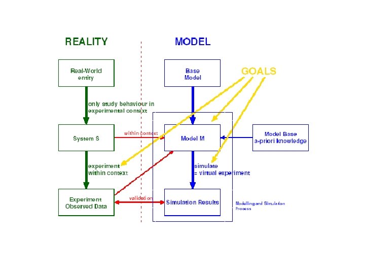
MODEL • Model is an abstraction (essence) of a real system. It is a representation of reality. • A model of a system is a tool to answer questions about the system without having to do an experiment. • Different models can be constructed for different purposes. • An abstracted models may be: – Verbal models (vague) – Mathematical models (precise). • The word model is derived from Latin and it’s meaning is mould or pattern (physical model). • Modeling is a process of abstraction of a real system.
Simulation • Simulation is derived from Latin simulare which means pretend. • Simulation is thus an inexpensive and safe way to experiment with the system model. • However, the simulation results depends completely on the quality of the system model.
Simulation can tell us things we don’t already know.
BENEFITS OF USING SIMULATION • Simulation points out modeler’s own ignorance and give a Detailed Look at Your System • Improve Staff and Equipment Efficiency • Try Out Many Different Scenarios § Save Time and Money § Simulation Improves the Quality of Analysis § Simulations create virtual Environments
WHEN TO USE SIMULATIONS ? • Changing one part of your strategy, results in cascading changes throughout your organization. • Simulation can help you in gaining the confidence to make tough choices. • Many of the opportunities you are evaluating haven’t been tried before (New Ideas). • Many of the consequences of your decisions might only partially be under your control. This makes decision making messy, but simulation is good at handling these messes. • Making mistakes would be expensive and painful • The decision you are making is complicated and difficult to think.
Return-on-Investment Efficiency (Money) Effectiveness (Time) Risk Reduction (Environment, Lives) Simulation makes a real and positive difference in national military readiness and national productivity.
• SIMULATION PROVIDES Efficiency * Cost quantification in terms of savings or avoidance. - Higher mission availability - Increase operational system availability - Transportation avoidance - Reduce / Eliminates expendable costs - Less procurement & operational costs § Effectiveness * Positive Contribution that are seldom quantified - Improved proficiency / performance - Provide activities otherwise impossible short of combat - Provides neutral & opposition force - Greater observation / assessment / analysis capability § Risk Reduction * Safety * Environment * Equipment - What is the risk? Risk is the possibility of loss, damage, or any other undesirable event. - Where is the risk? Almost any change, good or bad , posses some risk. - How significant us the risk ? Once the risk is identified, a model can help you in quantifying it (putting a price on it). It also help you in deciding whether risk is worth taking.
Model Development SYSTEM Purpose Performance Measure Level of Boundaries Detail MODEL IMPLEMENTATION Design Alternatives
Steps in the modeling process • System Description • Gather experimental data that describe the system’s behavior • Investigate alternative models • Make the model • Validate the model § Show that the model behaves like the physical system § Simulate something not used in the model’s design § Perform a sensitivity analysis • • Integrate with models for other systems Analyze the performance of the model Re-evaluate and improve the model Suggest new experiments for the physical system
Modeling and simulation of Parachute § It is the building block of any recovery system. § The performance characteristics of parachute must be known for selecting and designing. § Parachutes are used for paratroopers, recovery of unmanned aircraft, missiles, ordinance devices, manned and unmanned space craft and for speed reduction of landing fighter aircrafts.
Heat generation in Parachute • A large amount of heat is generated during power packing and deployment of parachute. • Heat developed during packing may be controlled, but it is uncontrolled when parachute is deployed. • Heat generated due to interlayer friction and wall-fabrics friction. • Canopy is poor conductor of heat and irregular in shape. • Large temperature gradient is developed in canopy surface. • This may cause a major failure in the parachutes.
M&S of Heat generation in Parachute § Methodology: System Dynamics Technique § SDT the cause-effect relationships are identified among each pair of variables. § In SDT causal loop diagram and flow diagram have an important role. These diagrams offers convenient way to conceptualize the system.
Causal loop diagram Wall temp. , T + Room temp, Ta Adiabatic wall temp Taw Surface areas, s 1, s 2, s 3, s 4 + + Rate of change - of wall temp. - RT - Temp of environment Ts Specific heat of canopy material, C Radiation shape factor FS + + Rate of change of energy stored by canopy, RE + + Mass of canopy, M Energy stored by canopy, E
Flow diagram Wall temp. , T Adiabatic wall temp Taw Rate of change of wall temp. RT Radiation shape factor FS Room temp, Ta s 1, s 2, s 3, s 4 Specific heat of canopy material, C Temp of environment Ts Mass of canopy, M Rate of change of energy stored by canopy, RE Energy stored by canopy, E
Dynamo Equations T. k=T. j + dt * RT. jk RT. kl = (CC. k+L*A*S 2 –BB. k – AA. k)/ (M*C) AA. k=c 1*FS*E*S 4*(T. k 4 – TA 4) BB. k=c 1*S 3*E*(T. k 4 – TA 4) CC. k=H*S 1*(Taw – T. k) E. k=E. j + dt*RE. jk RE. kl=M*C*RT. kl
Simulation T RT Time, sec.
Modeling and Simulation of Parachute. M. Tech. Dissertations guided B. R. Gupta (ADRDE), An innovative approach for modeling and simulation of parachute inflation and its performance, 1993. Bahadur, K. (ADRDE), Modelling and Simulation Performance Characteristics of Flexible Aerodynamic Deceleration Device, Dec. , 1993. Work Published - Chaturvedi, D. K. , and Gupta, B. R. , Simulation of Temperature Variation in Parachute Inflation, J. of The Institution of Engineers (India), AS, Vol. 76, Sept. 1995, pp. 2931. - Chaturvedi, D. K. , and Gupta, B. R. , Heat Generation Modelling During Parachute Packing and Deployment, National Conference on System Design and Simulation (SYDSIM), Agra, April 30 – May 2, 1992. - Chaturvedi, D. K. , Bahadur, K. , and Gupta, B. R. , An Innovative Approach for Predicting the Selected Performance Characteristics of Aerodynamics deceleration Device, Proc. Of National Systems Conference (NSC – 92), pp. 123 – 126, Madras, 1992. - Chaturvedi, D. K. , Gupta, B. R. , and Bahadur Kunwer, Performance Evaluation of Parachute During Inflation, Proc. Of National Systems Conference (NSC – 94), D. E. I. , Dayalbagh, pp. 232, Agra, Jan. 14 – 16, 1995.
Aircraft Landing Control System M. Tech. Dissertations Guided Mahadev B. Alloli, Intelligent Control System for Aircraft Landing, April 98. Ramawadh Chauhan, Automatic Aircraft Landing Control System Using Neural Networks, Dec. 1998, Published Chaturvedi, D. K. , Ramawadh Chauhan & Kalra, P. K, Applications of Generalised Neural Network for Aircraft Landing Control System, Int. J. on Soft Computing, Springer- Verlag, Vol. 6, No. 6, Sept. 2002, pp. 441 -448.
Aircraft Arrester Barrier System M. Tech. Dissertation Guided R. K. sharma (ADRDE), Performance characteristics of Aircraft Arrester Barrier System”, 1994 Published – Chaturvedi, D. K. , and Sharma, R. K. , An Experimental Study of Initial Tension of Suspension Strap of Aircraft Arrester Barrier System, National Systems Conference, PSG College of Technology, Coimbatore, pp. 474 – 481, Coimbatore, Dec. 14 – 16, 1995. – Chaturvedi, D. K. , and Sharma, R. K. , Modelling and Simulation of Force Generated in Stanchion System of Aircraft Arrester Barrier System, Int. J. of Modelling, Measurements, and Control, France, B, Vol. 64, No. 2, 1996, pp. 33 -51.
Aircraft Arrester Barrier System AABS • This is installed at the end of runway for the purpose of arresting combat aircrafts while overshooting runway lengths during aborted takeoff and emergency landings. • Various parts of AABS: – – – Stanchion system Energy Absorber System Tape retrieval system Tape and suspension system Electrical systems and their Control systems
Existing Energy Absorbing System • It consists of two velocity sensitive turbine type rotatory hydraulic energy absorbers. • It has a housing and a rotor, both consists of blades. • Rotor rotates in fluid and due to fluid friction brakes applied on it. Housing Rotor
Problems of Existing Energy Absorbing System • There is no control on braking torque of Existing energy absorbing System. • The Existing EAS is highly nonlinear in nature. The initial braking torque is very high but once it starts rotating, torque reduces to a significant low value. • For different types of aircrafts (weights) needs different aircraft arrester barrier systems or modified energy absorbing system (i. e. different drum diameters). • All the energy is wasted in the form of heat.
Proposed Energy Absorber • To overcome the drawbacks of existing energy absorbing system and provide back up to it an Eddy current EAS is proposed. • Proposed EAS could be the combination of existing system and eddy current EAS. Pe =K Bmax 2 f 2
Requirements for Eddy current EAS • High Voltage and high frequency Generator for Eddy current Energy Absorbing System. • Prime mover for rotating High Voltage Generator. • High voltage cables and suitable intelligent control system.
CONCLUSIONS n n n Basic Concepts of modeling and simulation. System Dynamics Technique of Modeling of some defence systems. -Parachute heat generation modeling during deployment. -Aircraft landing control system -Aircraft arrester barrier system.
Conclusion n n Energy absorber system is a crucial and very important part of Aircraft arrester barrier system. If there is any problem with this during operation whole AABS fails. Hence it is necessary to give some backup to Energy Absorbing system (EAS). The Eddy Current EAS along with hydraulic EAS is proposed. Eddy current EAS is fully controlled. The same Aircraft Arrester Barrier System could be used for different types aircraft (like light weight, heavy weight, etc. )
END END Faculty of Engineering, DEI