MLAT TDOA Multilateration is a navigation technique based

MLAT TDOA

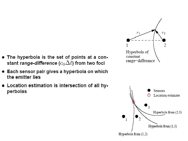
Multilateration is a navigation technique based on the measurement of the difference in distance to two or more stations at known locations that broadcast signals at known times. Unlike measurements of absolute distance or angle, measuring the difference in distance results in an infinite number of locations that satisfy the measurement.

When these possible locations are plotted, they form a hyperbolic curve. To locate the exact location along that curve, a second measurement is taken to a different pair of stations to produce a second curve, which intersects with the first. When the two are compared, a small number of possible locations are revealed, producing a "fix".

Multilateration is a common technique in radio navigation systems, where it is known as hyperbolic navigation. These systems are relatively easy to construct as there is no need for a common clock, and the difference in the signal timing can be measured visibly using an oscilloscope. This formed the basis of a number of widely used navigation systems starting in World War II with the British Gee system and several similar systems introduced over the next few decades. The introduction of the microprocessor greatly simplified operation, greatly increasing popularity during the 1980 s. The most popular hyperbolic navigation system was LORAN-C, which was used around the world until the system was shut down in 2010. Other systems continue to be used, but the widespread use of satellite navigation systems like GPS have made these systems largely redundant.

Multilateration should not be confused with trilateration, which uses distances or absolute measurements of time-of-flight from three or more sites, or with triangulation, which uses the measurement of absolute angles. Both of these systems are also commonly used with radio navigation systems; trilateration is the basis of GPS.


Principle Multilateration is commonly used in civil and military surveillance applications to accurately locate an aircraft, vehicle or stationary emitter by measuring the "Time Difference of Arrival" (TDOA) of a signal from the emitter at three or more receiver sites.

If a pulse is emitted from a platform, it will arrive at slightly different times at two spatially separated receiver sites, the TDOA being due to the different distances of each receiver from the platform. In fact, for given locations of the two receivers, a whole set of emitter locations would give the same measurement of TDOA. Given two receiver locations and a known TDOA, the locus of possible emitter locations is a one half of a two-sheeted hyperboloid.


In simple terms, with two receivers at known locations, an emitter can be located onto a hyperboloid. Note that the receivers do not need to know the absolute time at which the pulse was transmitted – only the time difference is needed.

Consider now a third receiver at a third location. This would provide a second TDOA measurement and hence locate the emitter on a second hyperboloid. The intersection of these two hyperboloids describes a curve on which the emitter lies.

If a fourth receiver is now introduced, a third TDOA measurement is available and the intersection of the resulting third hyperboloid with the curve already found with the other three receivers defines a unique point in space. The emitter's location is therefore fully determined in 3 D.

In practice, errors in the measurement of the time of arrival of pulses mean that enhanced accuracy can be obtained with more than four receivers. In general, N receivers provide N − 1 hyperboloids. When there are N > 4 receivers, the N − 1 hyperboloids should, assuming a perfect model and measurements, intersect on a single point.

In reality, the surfaces rarely intersect, because of various errors. In this case, the location problem can be posed as an optimization problem and solved using, for example, a least squares method or an extended Kalman filter


 used? • e 911 … cell phone")
Where is TDOA (time difference of arrival) used? • e 911 … cell phone location techniques • Loran C Navigation System (circ. 1957)

Loran-C … early example of Hyperbolic Location Technique based upon TDOA (accuracy about ¼ mile)

• Loran-C transmits wavelets that are used for timing. Both the time of arrival and carrier phase are used to extract information. • To identify individual Loran-C transmitters, codes are formed by grouping pulses into code words. • Pulse Position Modulation (PPM) can be used to carry additional information.

Loran-C Basics The basic “Loran-C like” system consists of three or more reference transmitting stations, each separated by a minimum amount of distance (TBD). Within the transmitting chain, one station is designated as Master while the rest are secondaries. The Master and Secondary stations transmit at precise time intervals. The receiver of interest measures the slight differences in the time that it takes for these signals to reach the receiver. In general, you could say that when the Master signal is received, it is the "Start" of the Stopwatch. When a secondary station is received it is the "Stop" for one TD. Again, the time difference from the receipt of the Master signal to a secondary is measured 1. This gives your second line of the TD. So, when the Master signal is received, it took so many nanoseconds until the receipt of the first secondary signal. It then took another so many nanoseconds until the receipt of the secondary, and so forth. The user can now plot their position on charts especially generated for Hyperbolic Location. Obviously, the position would actually be determined via algorithms that will convert the TD's to a more common coordinate system. Note 1: This important concept will be revisited on page 11 of this contribution.

TIME DIFFERENCE MEASUREMENTS The basic measurements made by Loran-C receivers are to determine the difference in the time-ofarrival (TD) between the master signal and the signals from each of the secondary stations of a chain. In Loran-C, each TD value is measured to a precision of about 100 nanoseconds or better. As a rule of thumb, 100 nanoseconds corresponds to about 30 meters. The principle of time difference measurements in hyperbolic mode is illustrated in the adjacent figure.
 & One Way Ranging (OWR) Mobile TX Anchor 1")
Time Difference Of Arrival (TDOA) & One Way Ranging (OWR) Mobile TX Anchor 1 RX Isochronous Anchor 2 RX TDOA Estimation To Anchor 1 TOF, 2 Info T 2 Anchor 3 RX Mobile Info T 3 TOF, 3 T 3 Anchor 2 Anchor 3 Passive Location TOA Estimation Info T 2 Info T 3 TDOA Estimation Isochronous
 are required")
Positioning from TDOA Anchor 3 3 anchors with known positions (at least) are required to find a 2 D-position from a couple of TDOAs (x. A 3, y. A 3) Anchor 2 (x. A 2, y. A 2) Mobile Measurements (xm, ym) Estimated Position Specific Positioning Algorithms Anchor 1 (x. A 1, y. A 1)

But TDOA can operate in one of two modes … • Mode 1 – The station of interest (SOI) receives multiple reference pulses and calculates the TDOA LORAN-C type operation and the processing burden is on the receiver to run the hyperbolic location algorithms • Mode 2 – The station of interest transmits a reference pulse which is received by multiple fixed nodes The fixed nodes must forward the TDOA information to a workstation which then runs the hyperbolic location algorithms 2 reference node SOI Key: Sync Pulse Location Pulse Position Report controller Mode 1 controller Mode 2 Key: Sync Pulse Location Pulse TDOA backhaul Note: The sync pulse accuracy determines the TDOA accuracy and hence the sync pulse requires a wideband transmission

Impact on PHY SAP and PLME in IEEE 802. 15. 4 a • The PHY is the only layer that has accurate knowledge of pulse arrival and carrier phase; hence, the actual TD calculation should be located in the PHY layer • As implied on page 5, the PHY will have to have a stop watch that can be used to determine the TD between the master and the slave pulses. This would be in the form of a high speed counter clocked at GHz rates. • The suggested metrics that are sent to higher layers by the PHY are: • Elasped Count (events per unit time – EPUT) • Time Resolution (dependent on high rate clock frequency) • This information would then be collected and used by higher layer applications to calculate hyperbolic location information • Multiple packet exchanges will have to be used to calculate the TD’s as shown in slide 8. The implication here is that a MAC command set will have to be added such that the DME initiates the ranging event and then the MAC autonomously completes the packet exchange. • It appears at first glance that TDOA is rather similar to TOA at the PHY layer and it is anticipated that the same PHY SAP interface should service both TOA and TDOA ranging/location techniques.

END.
- Slides: 29