
MISTRAL ASTRAL Sensors Flex feasibility study Gilles CLAUS
MISTRAL & ASTRAL Sensors Flex feasibility study Gilles CLAUS (on behalf of PICSEL-ALICE team of IPHC-Strasbourg)
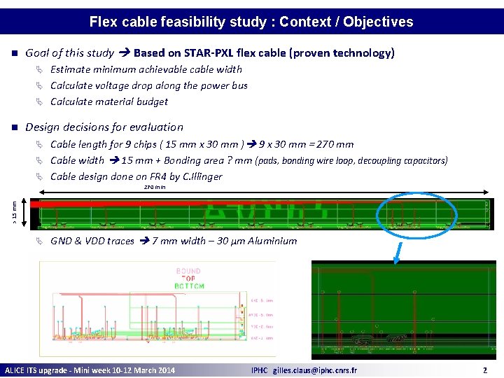
Flex cable feasibility study : Context / Objectives n Goal of this study Based on STAR-PXL flex cable (proven technology) Estimate minimum achievable cable width Ä Calculate voltage drop along the power bus Ä Calculate material budget Ä n Design decisions for evaluation Cable length for 9 chips ( 15 mm x 30 mm ) 9 x 30 mm = 270 mm Ä Cable width 15 mm + Bonding area ? mm (pads, bonding wire loop, decoupling capacitors) Ä Cable design done on FR 4 by C. Illinger Ä > 15 mm 270 mm Ä GND & VDD traces 7 mm width – 30 µm Aluminium ALICE ITS upgrade - Mini week 10 -12 March 2014 IPHC gilles. claus@iphc. cnrs. fr 2
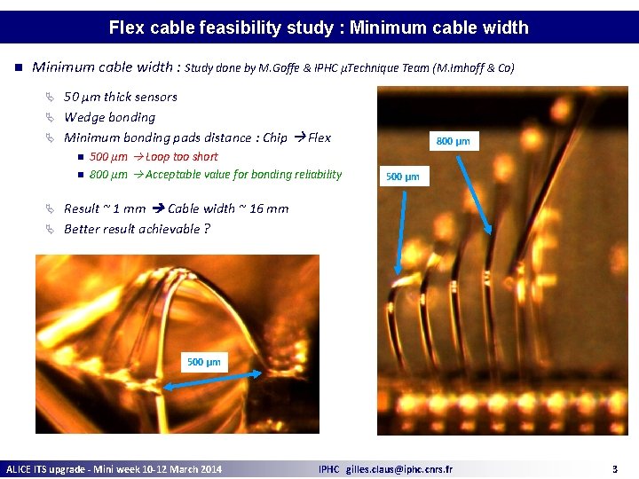
Flex cable feasibility study : Minimum cable width n Minimum cable width : Study done by M. Goffe & IPHC µTechnique Team (M. Imhoff & Co) 50 µm thick sensors Ä Wedge bonding Ä Minimum bonding pads distance : Chip Flex Ä n n 500 µm Loop too short 800 µm Acceptable value for bonding reliability 800 µm 500 µm Result ~ 1 mm Cable width ~ 16 mm Ä Better result achievable ? Ä 500 µm ALICE ITS upgrade - Mini week 10 -12 March 2014 IPHC gilles. claus@iphc. cnrs. fr 3
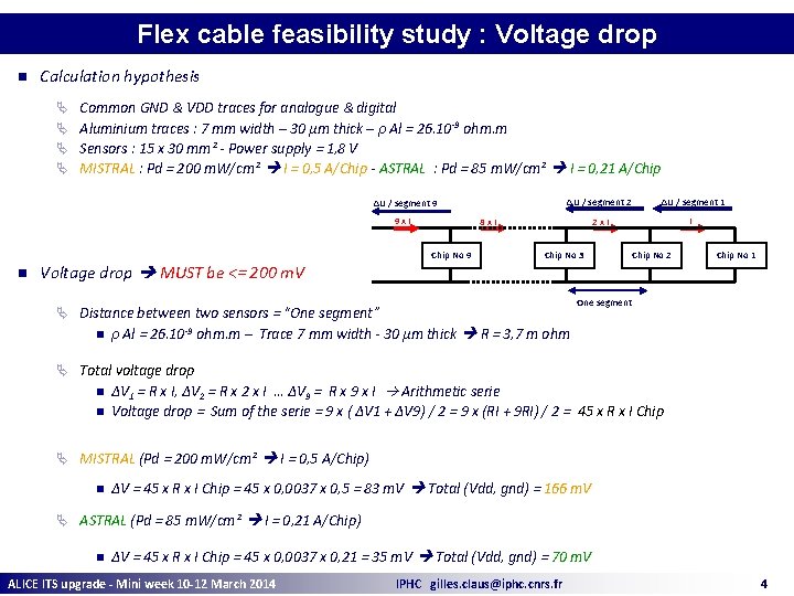
Flex cable feasibility study : Voltage drop n Calculation hypothesis Ä Common GND & VDD traces for analogue & digital Ä Aluminium traces : 7 mm width – 30 µm thick – ρ Al = 26. 10 -9 ohm. m Ä Sensors : 15 x 30 mm² - Power supply = 1, 8 V Ä MISTRAL : Pd = 200 m. W/cm² I = 0, 5 A/Chip - ASTRAL : Pd = 85 m. W/cm² I = 0, 21 A/Chip ΔU / segment 9 9 x. I n Voltage drop MUST be <= 200 m. V ΔU / segment 2 ΔU / segment 1 2 x. I I 8 x. I Chip No 9 Chip No 3 Chip No 1 One segment Ä Distance between two sensors = “One segment” n Chip No 2 ρ Al = 26. 10 -9 ohm. m – Trace 7 mm width - 30 µm thick R = 3, 7 m ohm Ä Total voltage drop n n ΔV 1 = R x I, ΔV 2 = R x 2 x I … ΔV 9 = R x 9 x I Arithmetic serie Voltage drop = Sum of the serie = 9 x ( ΔV 1 + ΔV 9) / 2 = 9 x (RI + 9 RI) / 2 = 45 x R x I Chip Ä MISTRAL (Pd = 200 m. W/cm² I = 0, 5 A/Chip) n ΔV = 45 x R x I Chip = 45 x 0, 0037 x 0, 5 = 83 m. V Total (Vdd, gnd) = 166 m. V Ä ASTRAL (Pd = 85 m. W/cm² I = 0, 21 A/Chip) n ΔV = 45 x R x I Chip = 45 x 0, 0037 x 0, 21 = 35 m. V Total (Vdd, gnd) = 70 m. V ALICE ITS upgrade - Mini week 10 -12 March 2014 IPHC gilles. claus@iphc. cnrs. fr 4
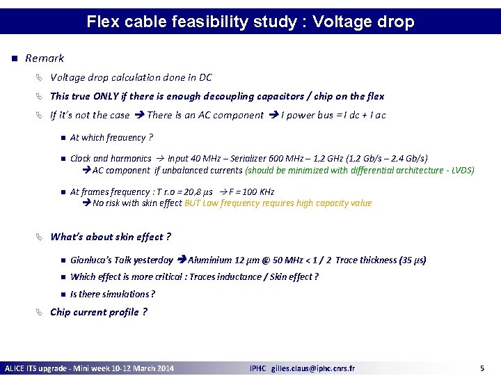
Flex cable feasibility study : Voltage drop n Remark Ä Voltage drop calculation done in DC Ä This true ONLY if there is enough decoupling capacitors / chip on the flex Ä If it’s not the case There is an AC component I power bus = I dc + I ac Ä Ä n At which freauency ? n Clock and harmonics Input 40 MHz – Serializer 600 MHz – 1, 2 GHz (1, 2 Gb/s – 2, 4 Gb/s) AC component if unbalanced currents (should be minimized with differential architecture - LVDS) n At frames frequency : T r. o = 20, 8 µs F = 100 KHz No risk with skin effect BUT Low frequency requires high capacity value What’s about skin effect ? n Gianluca’s Talk yesterday Aluminium 12 µm @ 50 MHz < 1 / 2 Trace thickness (35 µs) n Which effect is more critical : Traces inductance / Skin effect ? n Is there simulations ? Chip current profile ? ALICE ITS upgrade - Mini week 10 -12 March 2014 IPHC gilles. claus@iphc. cnrs. fr 5
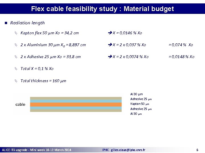
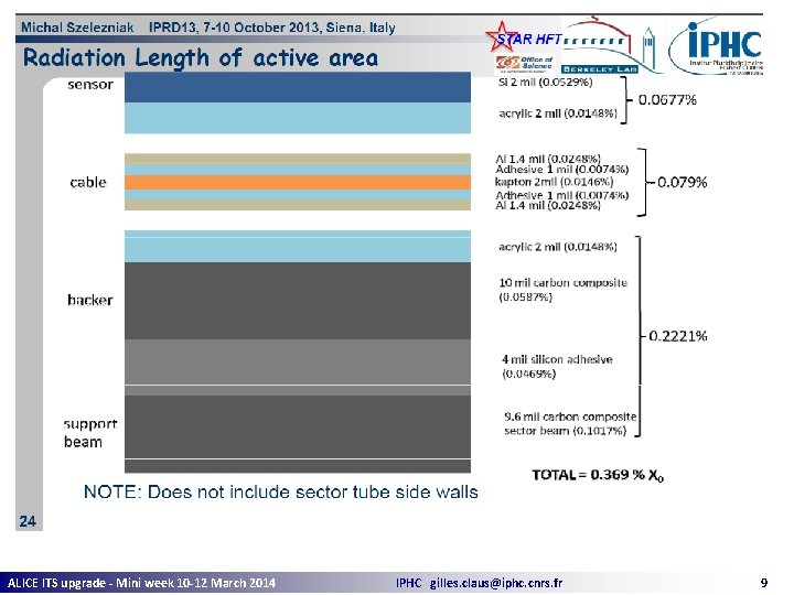
Flex cable feasibility study : Material budget n Radiation length Ä Kapton flex 50 µm Xo = 34, 2 cm X = 0, 0146 % Xo Ä 2 x Aluminium 30 µm X 0 = 8, 897 cm X = 2 x 0, 037 % Xo = 0, 074 % Xo Ä 2 x Adhesive 25 µm Xo = 33, 8 cm X = 2 x 0, 0074 % Xo = 0, 0148 % Xo Ä Total X = 0, 1 % Xo Ä Total thickness = 160 µm Al 30 µm Adhesive 25 µm Kapton 50 µm Adhesive 25 µm Al 30 µm ALICE ITS upgrade - Mini week 10 -12 March 2014 IPHC gilles. claus@iphc. cnrs. fr 6
Flex cable feasibility study : Conclusion n n Flex Ä Does it makes sense to continue this study ? Ä Now it’s a design in a CAD tools Nothing has been produced Ä Is there manpower to pursue this study ? Power distribution – Voltage drop Ä Definition of minimum decoupling capacitors value / chip Ä Skin effect / Traces inductance Ä Chip current profile ALICE ITS upgrade - Mini week 10 -12 March 2014 IPHC gilles. claus@iphc. cnrs. fr 7

Backup ALICE ITS upgrade - Mini week 10 -12 March 2014 IPHC gilles. claus@iphc. cnrs. fr 8
ALICE ITS upgrade - Mini week 10 -12 March 2014 IPHC gilles. claus@iphc. cnrs. fr 9
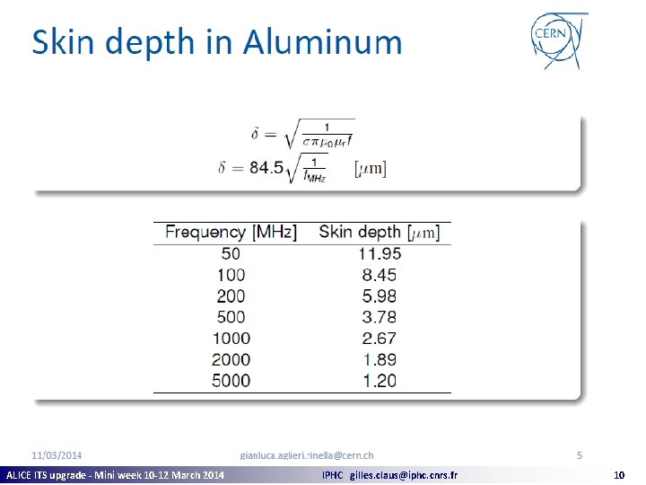
ALICE ITS upgrade - Mini week 10 -12 March 2014 IPHC gilles. claus@iphc. cnrs. fr 10
- Slides: 10