Ministry of Higher Education and Scientific Research AlMustansiriyah

 and Inductors Capacitors : A circuit element that is composed of two")

")
")
 Q i c (t) C dt i c")

 vc (t) ic (t) Pc (t) v")
 τ t P τ dτ c τ dv")
 C v c 2 (t) 2")

 2. Pc(t) 3. wc(t) dv c (t) (1) i")
 2 µA t - 2µ A (2) dv c (t) Pc(t)")

 4 µJ 4 e 2 (t 1) 4 t 2 1")
 2. Power delivered to the capacitors at t = m S.")

 20. 79 W 80 (3) Find WC (t) Π m)")


 v L (t) L dt 1 di")
 v L (t) i L (t) di L")
 P Τ DΤ L τ τ")


- Slides: 26
Ministry of Higher Education and Scientific Research Al-Mustansiriyah University Faculty of Engineering Computer Engineering Department Electrical Eng. Lab 1' class Assistant Lecturer Hazim alkargole 2017 20189 ﻭﺯﺍﺭةﺎﻟﺘﻌﻠﻴﻢ ﺍﻟﻌﺎﻟﻲ ﻭﺍﻟﺒﺤﺚ ﺍﻟﻌﻠﻤﻲ ﺍﻟﺠﺎﻣﻌﺔ ﺍﻟﻤﺴﺘﻨﺼﺮﻳﺔ ﻛﻠﻴﺔ ﺍﻟﻬﻨﺪﺳﺔ ﻗﺴﻢ ﻫﻨﺪﺳﺔ ﺍﻟﺤﺎﺳﻮﺏ
CHAPTER (5) and Inductors Capacitors : A circuit element that is composed of two conducting plates or surfaces separated by a dielectric (non conducting) materials + A + C - circuit symbol
Let A : surface area of each plate d : distance between the two plates Capacitance As Area Capacitance As distance C A d It is found that ε 0 A C d Where : ε 0 Permittivity of free space
ε 0 8. 85 *10 12 F m • If a voltage source (v) is connected to the capacitor , +ve charge will be transferred to one plate while –ve charge will be transferred to the other plate. Let the charge stored at the capacitor q If v , q v q It has been found that q cv
C is the capacitance CQ V Current in capacitor : We know that i(t) d q(t) dt i c (t) d c v c (t) dt dv c (t) i c (t) C dt
Voltage of capacitors dv c (t) Q i c (t) C dt i c (t) dt C dvc (t) d v c (t) 1 i c (t)dt C 1 v c (t) v c (t 0) C Where t 0 : initial time τ t i (τ ) dτ c τ t 0
NOTE : Capacitors only store and release ELECTROSTATIC energy. They do not “creat e” The capacitor is a passive element and follows the passive sign convention Linear capacitor circuit representation i(t) C dv (t) dt
Power of the capacitors : Pc (t) vc (t) ic (t) Pc (t) v c (t) C dv c (t) dv (t) C vc (t) c dt dt or 1 Pc (t) i c (t) v c (t 0 ) C i c τ dτ τ t 0 τ t
Energy of capacitor w c (t) τ t P τ dτ c τ dv c τ dτ C v c τ dτ τ τ t vc (t) C v τ dv τ c c vc ( ) v c (t) 2 1 C v c τ | v (- ) c 2 2 2 1 1 C v c t C v c 2 2
Assuming V C 0 1 w c (t) C v c 2 (t) 2 q (t) v c (t) C 1 q 2 (t) w (t) C c 2 C 2 1 2 w c t q (t) 2 C
EXAM PLE: The following voltage is imposed across the terminals of a 0. 5 F capacitor. 0 V , t 0 v c (t) 4 t V , 0 t 1 4 e t 1 V, 1 t v (t) 4 1 2 3 t
Find the following: 1. ic(t) 2. Pc(t) 3. wc(t) dv c (t) (1) i c (t) C dt 0 d i c t C 4 t 4 C 2 µ A dt d t 1 (t 1) 4 e 4 C 1 e 2 e µA C dt t 0 0 t 1 1 t
i C (t) 2 µA t - 2µ A (2) dv c (t) Pc(t) C vc (t) dt 0. 5µ F 0 dv c t 0 W dt 0. 5µ F 4 t 4 8 t µW 0. 5µ F 4 e t 1 8 e 2 t 1 t 0 0 t 1 µW 1 t
P C a. Charging b s o r b e d. Power power 8µ A 1 t -8µ A (3) s. Discharging u p p l i e d p o. Power 1 2 C v c (t) 2 0 1 2 w c (t) 0. 5µ F 4 t 2 µJ 2 1 0. 5µ F 4 e t 1 2 4 e 2 t 1 2 w c (t) t 0 0 t 1 µJ 1 t
w C (t) 4 µJ 4 e 2 (t 1) 4 t 2 1 t Example : The voltage at the terminals of a 0. 5 F capacitor is 0 vc (t) 20000 t sin(40000 t) V 100 e t 0
Find: 1. i(0) 2. Power delivered to the capacitors at t = m S. 3. Energy stored in the capacitor at t = 80 m S i (t) C dv c (t) dt
C D 100 E 20, 000 T dt SIN 40, 000 T C 100 e 20, 000 t cos (40, 000 t)(40, 000) sin(40, 000 t) ( 2 *106 e 20, 000 t ) i c (0) 0. 5 *10 6 100 (1) (40, 000) 0 i c (0) 2 A (2) Π m P Find C 80 ? dv c (t) Pc (t) C v c (t) , t 0 dt 0. 5µ F 100 e 20, 000 t sin 40, 000 t * 100 e 20, 000 t cos (40, 000 t) (40, 000) sin (40, 000 t) ( 2 *106 e 20, 000 t )
Π PC ( m) 20. 79 W 80 (3) Find WC (t) Π m) 80 (discharging) ? 2 1 1 C v C 2 (t) C 100 e 20, 000 t sin (40, 000 t) 2 2 Π WC ( m) 519. 2 µ J 80
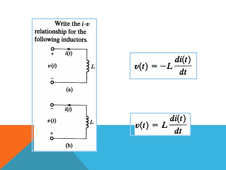
INDUCTO RS : Inductors are circuit elements that consist of a conducting wire in the shape of a coil Circuit representation for an inductor
• If a current is flowing in the inductor, it produce a magnetic field , (T) • The direction of ( depends on the right-hand rule. LI(T) Where L is the inductance and measured in Henry [H] • As the current increases or decreases, the magnetic field spreads or collapse • The change in magnetic field induces a voltage across the inductor. d (t) VL (t) dt di L (t) VL (t) L dt
Current in inductors : di L (t) v L (t) L dt 1 di L (t) v L (t) dt L Integrate both sides as before 1 i L (t) i L (t 0 ) L τ t v τ dτ τ t 0
Power in inductor : PL (t) v L (t) i L (t) di L (t) L dt di L (t) PL (t) L i L (t) dt τ t 1 v τ dτ PL (t) v L (t) i L (t 0 ) L τ t 0
Energy in inductors: τ t W L (T) P Τ DΤ L τ τ t L i L τ τ di L τ dτ dτ As before w L (t) 1 Li 2 2 L (t)
Example : The current flow through an 100 m H inductor 0 A i. L (t) 5 t 10 t e t 0 A Find : (1) Maximum value of current. (2) v. L(t) , (3) PL(t) , (4) w. L(t) i. L(t) First, find t max di (t) let L 0 i. L(max) dt 10 t 5 e 5 t 10 0 e 5 t 50 t 10 0 tmax 0. 2 sec t max t
i. Lmax I L 0. 2 10 0. 2 E 5 0. 2 2 e 1 0. 736 A (2) di L (t) v L (t) L dt d 0. 1 H 10 t e 5 t dt 0. 1 e 5 t 50 t 10 e 5 t 1 5 t , t 0 0 v L (t) 5 t e (1 5 t) , t 0