Minia University Faculty of Engineering Prod Eng Mechanical


 It is used to draw inclined lines or objects. You")


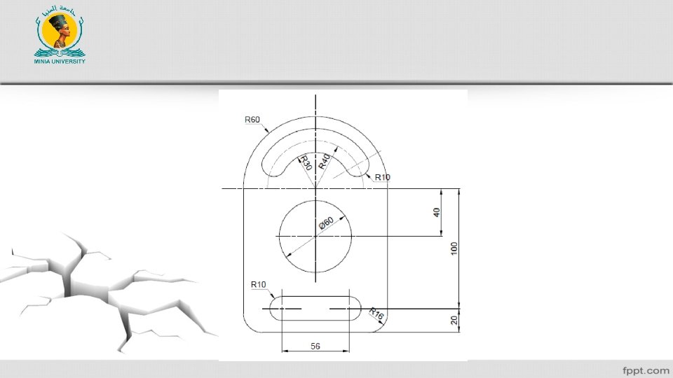

- Slides: 19
Minia University Faculty of Engineering Prod. Eng. & Mechanical Design Dept. Computer Applications in Engineering (Lecture 5) By/ Dr Ahmed Ibrahim E-mail: ahmedkhalifa@mu. edu. eg Tel: +201117400743
Learning Objectives 1. Learning how to use the status bar to ease the drawing. 2. Editing commands. 3. Drawing Examples step by step.
Status bar The main advantage of status bar is to facilitate the drawing process. Additionally, it save the drawing process.
• Infer Constraints The main function of “Infer Constraints” is to show the relations between the drawn objects. To activate this option, you can left click on the icon to turn it from “Gray” to “Blue” color. Infer Constraints is deactivated Infer Constraints is activated
• Dynamic input The main function is that-when activated- all of input data will be considered as a relative. “No need to insert @ before the dimensions”. • Ortho mode This option restrict the cross hair to move with inclined planes. It means that it is suitable to draw horizontal and vertical line only. You can activate this option by pressing F 8.
Polar Tracking (F 10) It is used to draw inclined lines or objects. You can adjust the angles through clicking the arrow beside the circle in the polar tracking icon. Object snap tracking (F 3) It is useful to specify certain points to draw objects from like (End points, Midpoint, centers, etc. ). You can select more points by clicking the arrow beside the rectangle in the Osnap tracking icon.
Line weight It is used to show the real line weights.
Editing tools Most of editing tools are existed in “Modify” ribbon panel from “Home” ribbon tab. You can move, rotate, erase, copy, and so many editing options are offered in this panel.
1. Move This command is used for moving objects from point to another place in the workspace. This command is activated through clicking on OR write “move” in the command bar. OR just write “m”. Then, select the object to be moved. You have to choose the base point, then you have to enter the destination coordinate.
2. Rotate This command is used for rotating the objects. To use this command, just click on this icon OR write “rotate” OR “RO”. You can accomplish this command by clicking the “rotate” command, Then select the object to be rotated. You have to select the base point to rotate thee object about, then enter the angle.
3. Erase This command is used to delete or erase the previously drawn objects. You can activate this command by clicking on OR write “Erase”, OR “E”. What is the difference between “Erase” and “Power erase”?
4. Copy This command is used to copy objects. You can click on OR write “Copy” OR “co”. The same steps as previous commands.
5. Mirror You can accomplish this command by clicking on “Mirror” OR write “mirror” OR “mi”. This command is used to redraw a half of a symmetric draw. to accomplish this command, you can activate the command before selecting the symmetric objects. Then, select the mirror line “Axis of symmetry”.
6. Trim It is used to remove the flashes from a certain parts. You can click on “Trim” OR write “trim” OR “tr”. Cutting edge Flashes to be removed
You have to identify the cutting edge “object”, then click “enter”. After that, click on the object to be cut, exactly on the part of the object to be cut. The other way is to activate “Trim” and then click “Enter” means “Select all”, and then click on the object to be cut. “more flexible”.
7. Extend It is used to extend the un completed lines and arcs. To accomplish this command, you can click on OR write “extend” OR “ex”.
After activating the command, click on the object that you want to extend to, Press “Enter” after that. Click on the object that you want to extend.
All Questions Are Warmly Welcome