MIL STD MIL STD 461 F DEF STAN


 A. 시험목적 -개폐접점에 의한 Transient")

 A-18")


 2 NRS 04 LIMITS A test level")
- Slides: 33
군용 부속시설 별 시험항목 선택 및 MIL STD규격비교 -MIL STD 461 F -영국, DEF STAN 59 -411 -NATO, AECTP-500 경고 : 본 자료는 한국기술연구소 소유로 무단 복제를 금함 A tree which has a deep and wide spread roots since 1987 Korea Technology Institute emc. re. kr minkti@naver. com A-1
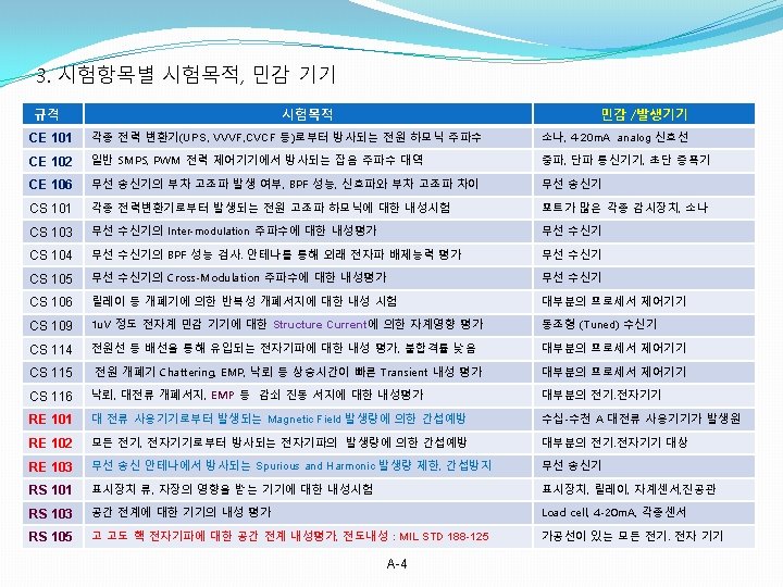
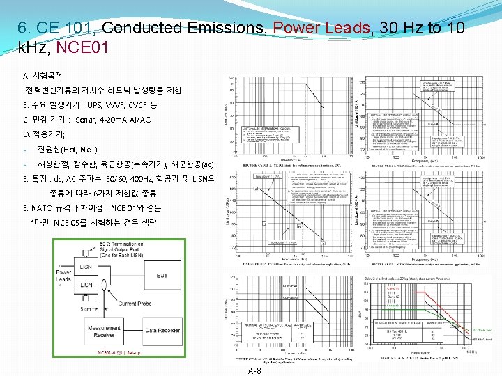
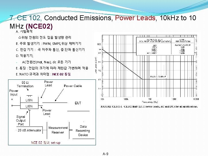
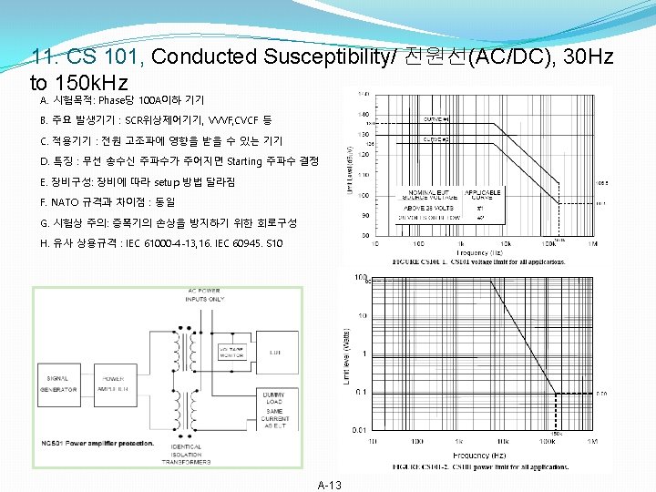
1. MIL STD 461 F/ DEF STAN 59 -411/ NATO AECTP 500 / 대응 상용규격 비교 MIL STD 461 F, 10 th 12. 2007(18종) DEF STAN 59 -411(영국) 01. 2008(13종) NATO AECTP-500 4 th 11. 2011 (24종) CE 101, 전원선, 30 Hz-20 k. Hz CE 102, 전원선, 10 k. Hz-10 MHz DEC 01, 전원 1차 측, 20 Hz-150 MHz NCE 01, 전원선, 30 Hz-10 k. Hz DCE 02, 제 어 , 신 호 , 전 원 2차. 20 Hz- NCE 02, 전원선, 10 k. Hz-10 MHz 150 MHz NCE 05, 전 원 , 신 호 및 제 어 선 , 30 Hz 150 MHz DCE 03, 전 원 1차 측 , Exported NCE 04, Exported transient, 전원선 개폐 transient 서지 CE 106, 안테나, 10 k. Hz-18 GHz NCE 03, 안테나, 10 k. Hz-18 GHz CS 101, 전원선, 30 Hz-150 k. Hz DCS 01, 전원 1차 측, 20 Hz-50 k. Hz NCS 01, 30 Hz-150 k. Hz, NCS 11 전원선( 함정) DCS 02, 제 어 , 신 호 및 전 원 , 50 k. Hz- NCS 02, 제어 및 신호선, 30 Hz-50 k. Hz 400 MHz DCS 03, 제어 및 신호선, 20 Hz-50 k. Hz DCS 10, ESD/정전기 NCS 12, ESD/ 정전기 CS 103, 안테나 IM, 15 k. Hz-10 GHz NCS 03, 안테나 단자 IM, 15 k. Hz-10 GHz CS 104, 안 테 나 Rejec. , 30 Hz. NCS 04, 안테나 Rejection, 30 Hz-18 GHz CS 105, 안 테 나 , Cross M, 30 Hz. NCS 05, 안테나 Cross M. , 30 Hz-18 GHz CS 106(F), Transient power leads NCS 10, 단발성 서지, 낙뢰/항공기 CS 109, Structure Current. 60 Hz 100 k. Hz CS 114, BCI , 10 k. Hz-200 MHz CS 115 BCI Impulse, 구형파 주입 CS 116 Damped sinusoidal, 10 k. Hz 100 Mz RE 101, MF, 30 Hz-100 k. Hz DRE 02, MF, 20 Hz-250 k. Hz RE 102, E-field, 10 k. Hz-18 GHz DRE 01. E-field, 10 k. Hz-18 GHz RE 103, 안 테 나 Spri/Har, 10 k. Hz- 대응 상용 규격 IEC 61000 -3 -2 CISPR 22 IEC 61000 -4 -4, EFT EN 301 -489 -XX, 300 -328 IEC 61000 -4 -13, 16. IEC 60945. S 10 IEC 61000 -4 -6 IEC 61000 -4 -2, ESD EN 301 -489 -XX, 300 -328 EN 301 -489 -XX IEC 61000 -4 -4, INS 4040 구형 파 NCS 06, Structure Current, 60 Hz-100 k. Hz NCS 07, BCI, 10 k. Hz-200 MHz NCS 08 , Lightning for aircraft, 30 Hz/ minute NCS 09, 정현 감쇠 진동 서지, 10 k. Hz 100 MHz NRE 01, MF, 30 Hz-100 k. Hz A-2 NRE 02, E-field, 10 k. Hz-18 GHz NRE 03, 안테나 S&H, 10 k. Hz-18 GHz IEC 61000 -4 -6 IEC 61000 -4 -4, INS 4040 IEC 61000 -4 -12 IEC 61000 -4 -8. 9, 10 CISPR 22 EN 301 -489 -XX, 300 -328
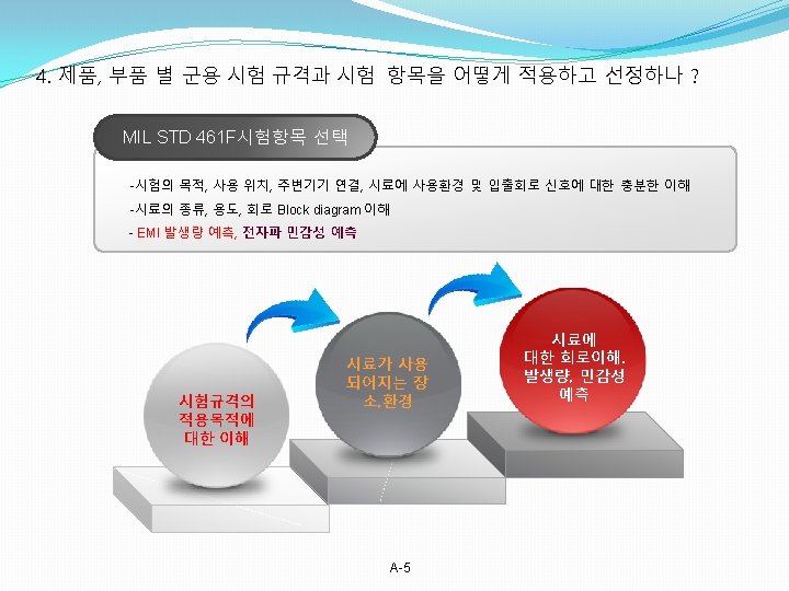
2. 각 군 주요 기기 별 MIL STD 461 F 시험항목의 적용 AECTP 500, NATO Summaries AECTP 500, NATO Applications A-3
5. MIL STD 461 F의 Emission과 Susceptibility level간의 에너지 Margin 비교 A-6
MIL STD 461 F 과 NATO 규격 비교 A-7
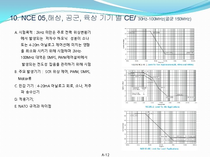
8. CE 106, Conducted Emissions/ 안테나 단자, 10 k. Hz to 40 GHz A. 시험목적 5. 6. 2 CE 106 limits. 무선 송수신기의 선택도 평가, 하모닉량 관리 Conducted emissions at the EUT antenna terminal shall not exceed the values gi B. 주요 발생기기 : 무선 송수신기 a. Receivers: 34 d. BμV C. 민감 기기 : 인접대역의 무선 송수신기 b. Transmitters and amplifiers (standby mode): 34 d. BμV D. 적용기기; c. Transmitters and amplifiers (transmit mode): Harmonics, except the second an -안테나 단자에서 전도적의 측정 and all other spurious emissions shall be at least 80 d. B down from the level at th E. 특징 : fundamental. The second and third harmonics shall be suppressed to a level of -2 F. 장비구성: or 80 d. B below the fundamental, whichever requires less suppression. E. NATO 규격과 차이점 : NCE 03과 동일 NCE-03의 경우; The second and third harmonics shall be suppressed 50 + 10 log p (where p = pe output in watts, at the fundamental) or 80 d. B, whichever requires less suppressio EUT Operating Frequency Range Start Frequency of Test - 10 k. Hz to 3 MHz : 10 k. Hz - 3 MHz to 300 MHz : 100 k. Hz - 300 MHz to 3 GHz : 1 MHz - 3 GHz to 40 GHz : 10 MHz A-10
9. NCE 04, 접점 개폐 Transient voltage limitation(Sea systems) A. 시험목적 -개폐접점에 의한 Transient 발생 전압 크기 제한 B. 주요 발생기기 : - Relay, AC/DC 개폐 스위치, 접점 C. 민감 기기 : 일반 프로세서 제어기기, 센서류 D. 적용기기; AC, DC 사용전압 별 제한 값 E. 특징 : 바리스터/MOV, Zenner diode F. NATO 규격과 차이점; -MIL STD 461 F에 없는 규격 a) For measurements at the EUT (Contactor Switching): The maximum voltage excursion of the superimposed exported transient, relative to the supply voltage waveform, shall not exceed: . 2000 V peak for 440 V 3 -phase AC equipment . 600 V peak for 115 V 1 -phase AC equipment . 2000 V peak for 720 V DC equipment . 960 V peak for 355 V DC equipment . 480 V peak for 28 V DC equipment The period for which any individual voltage excursion of the transient exceeds: . 1300 V peak for 440 V 3 -phase AC equipment . 400 V peak for 115 V 1 -phase AC equipment . 1300 V peak for 720 V DC equipment . 640 V peak for 355 V DC equipment . 320 V peak for 28 V DC equipment Shall not exceed 10 & S. (measured from the time the voltage exceeds these limits to the time it returns to, and remains within, the limits). The period for which the voltage excursion of the transient exceeds: . 1000 V peak for 440 V 3 -phase AC equipment . 300 V peak for 115 V 1 -phase AC equipment . 1000 V peak for 720 V DC equipment . 500 V peak for 355 V DC equipment . 250 V peak for 28 V DC equipment Shall not exceed 5 ms (measured from the time the voltage exceeds these limits to the time it returns to, and remains within, the limits). b. For measurements at the LISN (EUT Functional Switching): The maximum superimposed voltage excursion of the exported transient, relative to the supply voltage waveform, shall not exceed: . 200 V peak for 440 V 3 -phase AC equipment . 60 V peak for 115 V 1 -phase AC equipment . 200 V peak for 720 V DC equipment . 96 V peak for 355 V DC equipment A-11
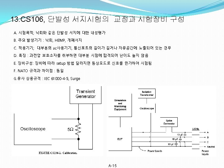
12. CS 103, CS 104, CS 105, CS 106 Limits 7. 1. 1 CS 103 limit for antenna port The EUT shall not exhibit any inter modulation products beyond specified tolerances when subjected to the limit requirement provided in the individual procurement specification 7. 1. 2 CS 104 limit for antenna port The EUT shall not exhibit any undesired response beyond specified tolerances when subjected to the limit requirement provided in the individual procurement specification. 7. 2. 3 CS 105 limit for antenna port The EUT shall not exhibit any undesired response, due to cross modulation, beyond specified tolerances when subjected to the limit requirement provided in the individual procurement specification. 7. 2 CS 106 limit, Transient for Power leads A-14
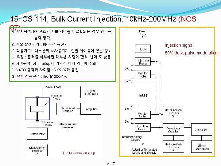
16. CS 114, Bulk Current Injection, 10 k. Hz-200 MHz (NCS 07) A-18
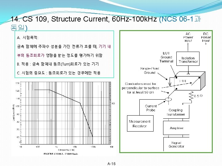
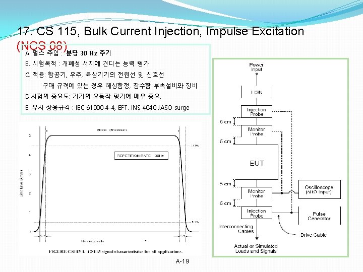
19. NCS 01, 02 -2, 전도내성/ NCS 03, 04, 05 = MIL 461 F CS 103, 104, 105 NCS 01, 전원선, 30 Hz-150 k. Hz NCS 02, 제어 및 신호선, 30 Hz-50 k. Hz NCS 03, 안테나 단자 IM, 15 k. Hz-10 GHz Inte-rmodulation products of 2 signals NCS 04, 안 테 나 Rejection, 30 Hz 18 GHz/20 GHz Out of band signal rejection NCS 05, 안 테 나 Cross M. , 30 Hz 18 GHz/20 GHz Cross modulation NCS 06, Structure current, 60 Hz-100 k. Hz NCS 07, Bulk cable injection, 10 k. Hz 400 MHz NCS 08, Bulk cable injection, Impulse excitation 시험목적: 개폐접점의 스위칭 서지, 채터링 A-21
20. NCS 08 Impulse / NCS 10, Imported Lightning/ Aircraft 비 교 A-22
21. NCS 11 & NCS 12, ESD A-23
22. MIL STD 461 F, RE 101 = NRE 01 set up and limit A-24
23. MIL STD 461 F RE 102 A-25
NRE 02 A-26
14. MIL STD 461 F RE 103 vs NRE 03 5. 18. 2 RE 103 limits. Harmonics, except the second and third, and all other spurious emissions shall be at least 80 d. B down from the level at the fundamental. The second and third harmonics shall be suppressed to a level of -20 d. Bm or 80 d. B below the fundamental, whichever requires less suppression. 측정거리 For transmitter frequencies less than or equal to 1. 24 GHz, the greater distance of the following relationships shall be used: R = 2 D 2/λ R = 3λ For transmitter frequencies greater than 1. 24 GHz, the separation distance shall be calculated as follows: For 2. 5 D < d use R = 2 D 2/λ For 2. 5 D ≥ d use R = (D+d)2/λ Calculate the transmitter ERP in d. BW, based on the receiver meter reading V, using the following equation: ERP = V + 20 log R + AF - 135 where: V = reading on the measurement receiver in d. BμV R = distance between transmitter and receiver antennas in meters AF = antenna factor of receiver antenna in d. B (1/m) Compare this calculated level to the measured level recorded in 5. 18. 3. 4 d 2. NRE 03 LIMITS Harmonics, except the second and third, and all other spurious emissions shall be at least 80 d. B down from the level at the fundamental. The second and third harmonics shall be suppressed to 50 + 10 log p (where p = peak power output in watts, at the fundamental) or 80 d. B, whichever requires less suppression A-27
14. MIL STD 461 F RS 101 vs NRS 01 -1, set up and limits A-28
16. MIL STD 461 F RS 103 vs NRS 03 -1 A-29
A-30
17. MIL STD 461 F RS 103 vs DRS-02, Reverberation chamber 측정환경 Reverberation chambers 장비구성 기존 RS 103측정방법과 Reverberation chamber방식 비교 Frank Leferink 및 미 해군 Naval surface warfare center응용사례 A-31
18. NRS 04 Radiated Susceptibility, Magnetic Field(DC) 2 NRS 04 LIMITS A test level of 800 A/m or higher (up to 4800 A/m for some submarine applications) shall be applied to simulate DC magnetic field effects. The test field shall be ramped continually up and down at a linear rate of 1600 A/m/s to the required test level. 19. Scan rate/time difference A-32