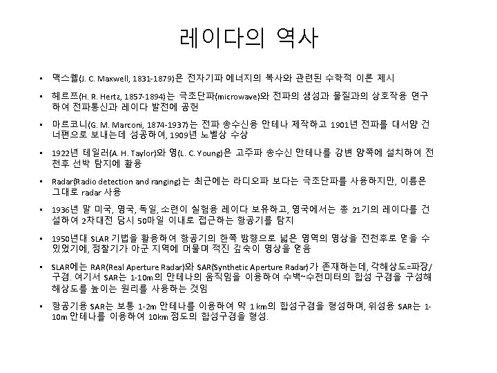
Microwave Remote Sensing Sidelooking Airborne RADAR SLAR System

마이크로파 원격탐사 Microwave Remote Sensing

 System antenna a. Pulse Generator Transmitter CRT Display or Digital")
Side-looking Airborne RADAR (SLAR) System antenna a. Pulse Generator Transmitter CRT Display or Digital Recorder b. t ransmitted pulse Duplexer • sends and receives Receiver b ackscattered pulse antenna

European Union: ERS-1, ERS-2, ENVISAT & Sentinel-1 A/B ERS-1: July 17 1991 - March 2000 ERS-2: April 21 1995 C-band, VV, Strip Envisat: Feb 28 2002 C-band, Dual Polarization Strip, Scan Sentinel-1 A (3 April 2014), Sentinel-1 B (25 April 2016) C-band, Dual Pol. (except for HH+VV) Interferometric Wide Swath Mode – main mode (250 km, 5 x 20 m) Strip, Extra-Wide, Wave 5

Canada: Radarsat-1 & Radarsat-2 Launch dates: Radarsat-1: Nov. 4 1995 C-band, HH Radarsat-2: December 14 2007 C-band, Quad-Pol. , Strip, Spot, Scan etc. 6

Japan: JERS-1 & ALOS-1/2 JERS-1: Feb. 1992 – Oct. 1998 L-band, HH, Strip ALOS: Jan. 24 2006 – May 2011 L-band, Quad-Pol. ALOS-2: May 24, 2014 7

Germany: Terra. SAR-X and Tan. DEM-X Launch dates: Terra. SAR-X: June 15 2007 Tan. DEM-X: June 21 2010 X-band, Dual Polarization Strip, Scan, Spot Modes *Single-pass Interferometer for Global DEM 8

Italia: COSMO-Sky. Med Launch dates: CSK 1: June 8, 2007 CSK 2: Dec. 9, 2007 CSK 3: Oct. 25, 2008 CSK 4: Nov. 5, 2010 X-band Constellation of 4 satellites Strip, Scan, Spot 9
 Commonly Used Frequencies Band Designations (common wavelengths Wavelength ( ) Frequency")
Active Microwave (RADAR) Commonly Used Frequencies Band Designations (common wavelengths Wavelength ( ) Frequency (f) shown in parentheses) in cm in GHz __________________________ K 1. 18 - 1. 67 26. 5 to 18. 0 Ka (0. 86 cm) 0. 75 - 1. 18 40. 0 to 26. 5 Ku 1. 67 - 2. 4 18. 0 to 12. 5 X (3. 0 and 3. 2 cm) 2. 4 - 3. 8 12. 5 - 8. 0 C (7. 5, 6. 0 cm) 3. 8 - 7. 5 8. 0 - 4. 0 S (8. 0, 9. 6, 12. 6 cm) 7. 5 - 15. 0 4. 0 - 2. 0 L (23. 5, 24. 0, 25. 0 cm) 15. 0 - 30. 0 2. 0 - 1. 0 P (68. 0 cm) 30. 0 - 100 1. 0 - 0. 3

SIR-C/X-SAR Images of a Portion of Rondonia, Brazil, Obtained on April 10, 1994

 방향 • look")
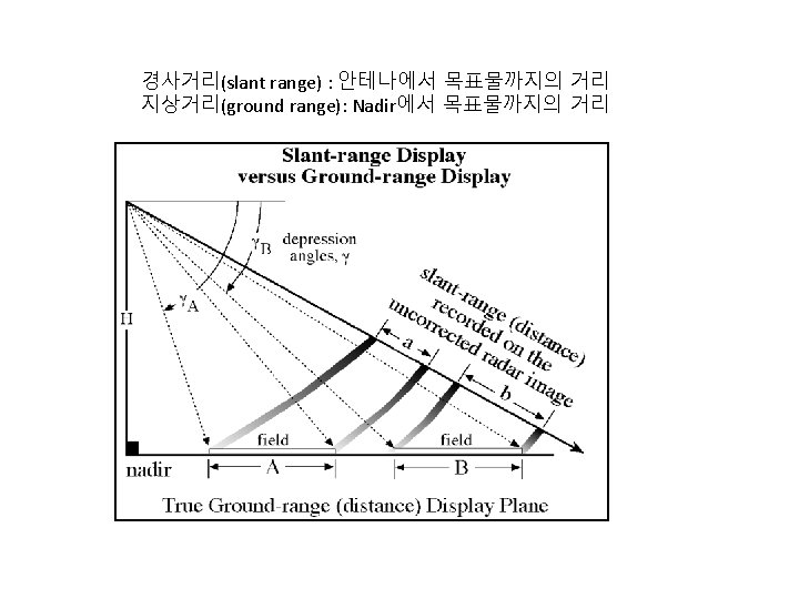
Radar Nomenclature • nadir: 연직방향 • azimuth flight direction: 방위 (비행) 방향 • look direction: 안테나와 목표간의 일직선 • range (near and far): 거리 • depression angle ( ): 부각 (수평면일 때, 부각= 90° 입사각) • incidence angle ( ): 입사각 • altitude above-ground-level, H • polarization: 편파

Look Direction
 • HH, VV는 like-polarized radar image • HV, VH는 cross-polarized radar image")
편파(Polarization) • HH, VV는 like-polarized radar image • HV, VH는 cross-polarized radar image
 •")
방위 해상도(Azimuth Resolution) •
 EX) ERS-1/2 SAR Antenna: 10 m x 1 m Altitude:")
합성구경레이다 (Synthetic Aperture Radar) EX) ERS-1/2 SAR Antenna: 10 m x 1 m Altitude: 785 km, sun-synchronous orbit Ground Velocity: 6. 6 km/s Look Angle: Right 17 -23 (20. 355 mid-swath) Incidence Angle: 19 – 26 (23 mid-swath) Slant Range: 845 km (mid-swath) Frequency: C- Band (5. 3 GHz, 5. 6 cm) Polarization: VV only Footprint : 100 km x 5 km Sampling Rate: 18. 96 MHz Pulse duration: 37. 1 s Range gate: ~ 6000 s Sampling Duration: ~ 300 s (5616 samples) Inter-pulse period: ~ 600 s (up to 10 pulses) Pulse Repetition Frequency: 1700 Hz Data Rate: 105 Mb/s (5 bits/sample) 19


Optical Image Correlation

Digital Image Focusing : SAR Range Compression Linear Chirp Signal £Chirp autocorrelation Function Matched Filtering For ERS-1/2, £ Pulse duration (T): 37. 1 s £ Bandwidth : 15. 5 MHz £ Half power width of autocorrelation function: 0. 065 s £ Pulse Compression Ratio: 575 (ERS-1/2) £ Ground Range Resolution: 12. 5 m 23
 Quadratic (Range Curvature) Azimuth FFT")
Range Migration Flight Path Point Target Linear (Range Walk) Quadratic (Range Curvature) Azimuth FFT 24
 Azimuth (s) After Range Walk Compensation Range Migration 25")
Range Migration Compensation Range (R) Azimuth (s) After Range Walk Compensation Range Migration 25
 : wavelength L:")
Azimuth Compression Synthetic Aperture Real Aperture Doppler Shift (Linear Chirp Pulse) : wavelength L: Antenna length For ERS-1/2, Coherent Integration Time (S): 600 ms (5 km footprint) Azimuth footprint width: 5 km (ERS-1/2) Matched Filtering Bandwidth: 1260 Hz Half power width of autocorrelation function: 0. 8 ms Pulse Compression Ratio: 756 (ERS-1/2) Azimuth Resolution: 5 m Azimuth Matched Filtering Output 26

SAR Focusing – Point Target azimuth range original After migration After range compression After azimuth compression 27
 28")
SAR Focusing Procedure (Range-Doppler Algorithm) 28

4 -look SAR Image 29


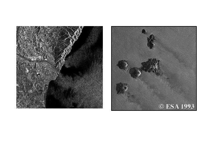
a. C-band ERS-1 depression angle =67° look angle = 23° b. c. X - band d. look direction L-band JERS-1 depression angle =54° look angle = 36° Aerial Photograph N

 •")
레이다 방정식(radar equation) •


토양수분과 투과: 건조 토양에서는 L-band의 경우 10 m까지 투과가 가능하지만 습윤 토양에서는 수mm도 투과하지 못함 Nile River Sudan Space Shuttle Color-Infrared Photograph SIR-C Color Composite: • Red = C-band HV • Green = L-band HV • Blue = L-band HH

Major Sources of RADAR Scattering from Woody and Herbaceous Vegetation Canopies

Response of A Pine Forest Stand to X-, C- and L-band Microwave Energy
 Image of Los Angeles")
Shuttle Imaging Radar (SIR-C) Image of Los Angeles

Aerial Photography and RADAR Imagery of the Pentagon in Washington, DC

RADARSAT Jensen, 2000

Geometric Relationship Between Two SAR Systems Used for Interferometry to Extract Topographic Information

Intermap X-band Star 3 i Orthorectified Image of Bachelor Mountain, CA and Derived Digital Elevation Model Jensen, 2000

Differential In. SAR Earthquake 44

DIn. SAR Volcano 45

One-Day DIn. SAR Terra Nova Bay Antarctica COSMO-SKYMED Descending CSK 2: 2010 -06 -16 CSK 3: 2010 -06 -17 46
")
Double-Differential In. SAR (DDIn. SAR)

SSM/I Passive Microwave Radiometer Image of the Amazon Barin Obtained at a Frequency of 85 GHz with Vertical Polarization
- Slides: 48