Microwave Remote Sensing of Soil Moisture Y S

 • Agriculture • Hydrology • Meteorology")


 or Measurement of crop canopy")


 Satellite http: //www. aqua. nasa. gov AMSR-E, Launched May 4, 2002")
 Resolution (km) 6. 6, 10. 65,")


 Resolution: 10")
")


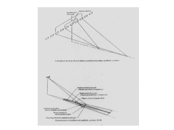
 2004 PALSAR (Phased array SAR) PRISM")
")


- Slides: 57
Microwave Remote Sensing of Soil Moisture Y. S. Rao CSRE, IIT, Bombay
Soil Moisture (SM) • Agriculture • Hydrology • Meteorology
Measurement Techniques Survey of methods for soil moisture determination, Water Resources Research, Vol. 16, No. 6, Page 961879, 1980, Schmugge et al. (1980) In Situ Methods • Gravimetric • Nuclear Techniques • Electromagnetic Techniques • Tensiometric Techniques • Hygrometric Techniques
Remote Sensing Methods • Visible & near IR – Reflected Solar • Thermal IR – Surface Temperature • Passive Microwave – Microwave Emission/Brightness Temperature • Active Microwave – Backscattering coefficient/dielectric properties
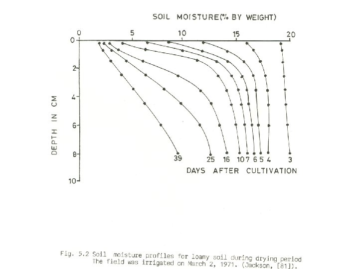
Gravimetric Techniques • Oven drying a soil sample at 1050 C for about 12 hours. Volumetric Soil Moisture (gm/cm 3) Yd Oven Dry Bulk Density
Nuclear Techniques • Fast neutrons emitted by an Americium 241: Beryllium radioactive source are themalised (slowed) by hydrozen in the test sample Advantages : SM can be measured at the any time, average SM can be measured with depth, system can be interfaced for automatic recording, temporal SM changes can be measured, readings are directly related SM Disadvantages : Surface soil moisture is not accurate, care must be taken to minimize health risks.
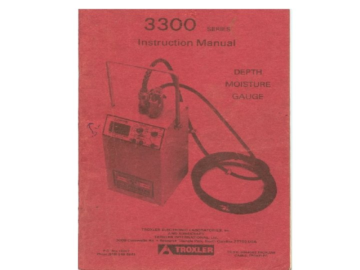
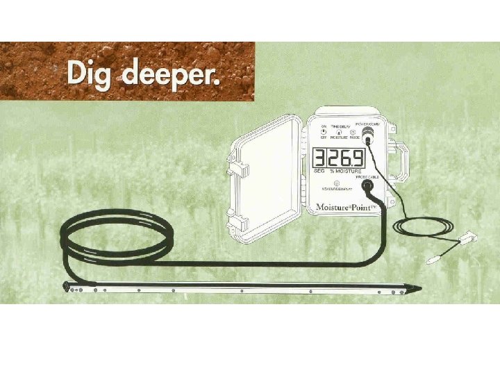
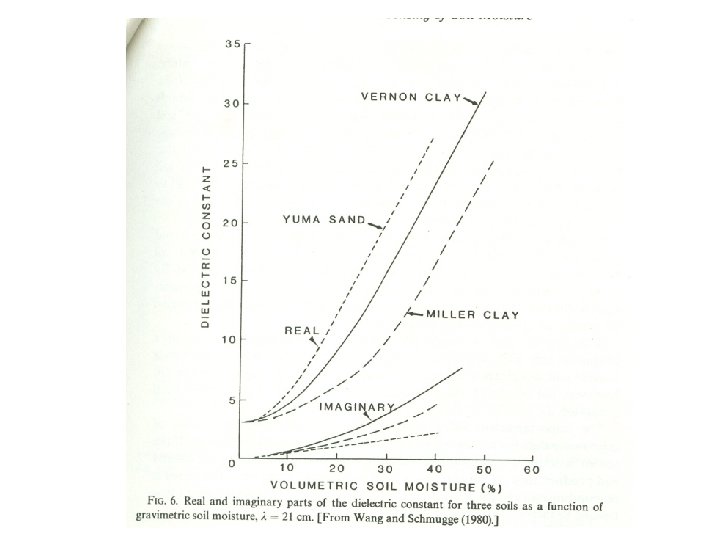
Electromagnetic Techniques • The technique is based on the electrical properties of the soil that varies with soil moisture. Resistivity or Capacitance between electrodes in a soil is measured for Soil moisture. Complex Dielectric Constant
Tensiometric Techniques Measures the capillary tension or the energy with which water is held (suction) by the soil. Tensiometers consist of porous ceramic cup connected by a continuous liquid column to a vacuum gauge or transducer. Advantages : easy to design, cost little, at any conditions in real time, placed in soil easily, Disadvantages : Only measures soil water suction, but only indirect measurement of soil moisture content; during installation, it may break.
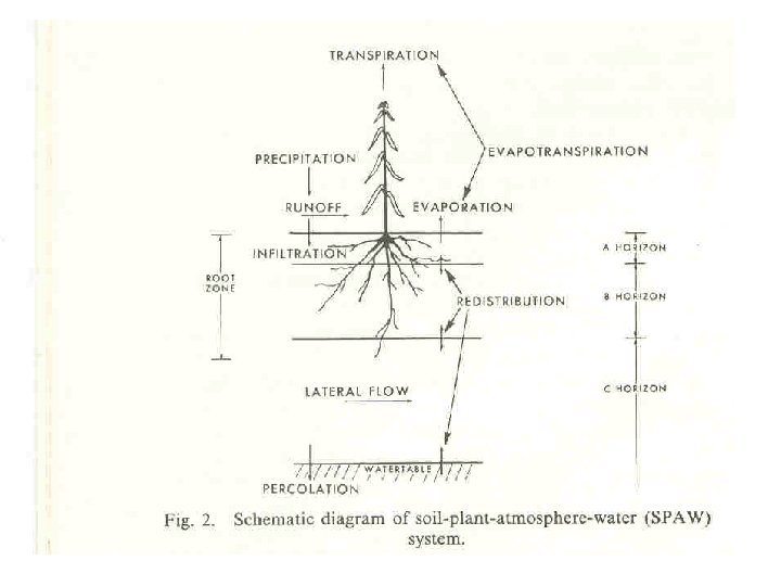
Soil Water Models SMt= SMt-1+P-R-L-E-T+C-Q SMt – Soil moisture at time t SMt-1 – Soil moisture at previous time P – Precipitation R – Surface Runoff L - net lateral subsurface outflow E –Evaporation or condensation T – Transpiration C – Capillary rise from lower levels Q - percolation • USDAHL Model • NWSRFS model
Remote Sensing Methods Visible Technique: Reflected solar energy is measured. (0. 4 – 1. 7 m) • Relationship between Reflectance and SM Depends on reflectance of dry soil, roughness, colour, illumination, organic matter, soil texture.
Thermal Infrared Techniques • Diurnal range of Surface Temperature(Tmax-Tmin) or Measurement of crop canopy – air temperature differential. • (Tmax-Tmin) depends on internal and external factors • Internal factors : Thermal conductivity(K) and heat capacity (C ) where P = (KC)1/2 is known as Thermal Inertia. K and C increases with Soil Moisture. • External Factors : solar radiation, air temperature, RH, cloudiness, and wind.
Diurnal Temperature Variation versus Soil Moisture
MODIS Data from Terra and Aqua Satellites Swath : 2330 Km and covers the same area 1 or 2 days Spectral Bands : 36 ; Wavelength : 0. 405 – 14. 385 Resolution : 250 m (bands 1 -2, 500 m (bands 3 -7), 1000 m(8 -36). Surface/Cloud Temperature 31 10. 780 - 11. 280 32 11. 770 - 12. 270 LANDSAT – 7 band-6 (10. 4 – 12. 5 microns, Resolution 60 m) ASTER Data : Band-13 : 10. 25 – 10. 95 Band-14 : 10. 95 – 11. 65
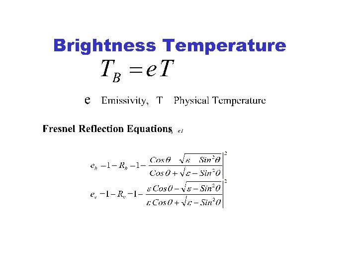
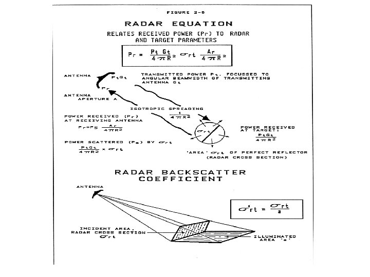
Microwave Remote Sensing 0. 3 - 300 GHz ( wavelength 1 m - 1 mm ) Passive (Radiation or TB ) Radiometers TB = e T Where e is emissivity and T is physical Temperature Active (Backscattering 0 d. B ) Radar 0 depends on dielectric properties of soil, geometric properties and system parameters.
Advantages • All weather Capability • Day-night ability • Penetration through a medium
Penetration
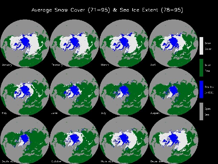
Passive Microwave Remote Sensing Emitted Radiation in Passive MRS
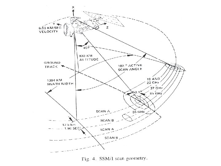
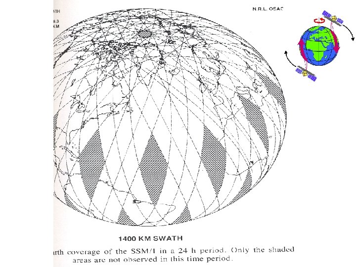
Radiometer Systems and their Parameters SSMR in NIMBUS 7 SSM/I IRS-P 4, MSMR EOS Aqua AMSRE ADEOS-II AMSR Launch date 1978 -87 1987/92/95 May 26, 1999 May 4, 2002 Jan. 16, 2004 Frequency (GHz. ) 6. 6, 10. 7, 18. 0, 21 and 37 GHz 19. 3, 22. 2 (V), 38. 0 and 85. 5 GHz 6. 6, 10. 65, 18, 21 6. 6, 10. 65, 18. 7, 23. 8, 36. 5, 89 Polarization H & V H &V (except 22. 2 GHz) H&V 6. 6, 10. 7, 18. 7, 23. 8, 36. 5, 89, (50. 3 V and 52. 8 V polarization only ) H&V (except last 2) IFOV (km x km) 148 x 95, 91 x 59, 55 x 41, 46 x 30, 27 x 18 69 x 43, 60 x 40, 37 x 28, 15 x 13 km 150 x 144, 75 x 72, 50 x 36, 50 x 36 km 76 x 44, 49 x 28, 28 x 16, 31 x 18, 14 x 8, 6 x 4 km 70 x 40, 46 x 27, 25 x 14, 2 8 x 17, 14 x 8, 6 x 3, 10 x 6 km Swath width (km) Revisit coverage(days) 822 km 1400 km 1360 1445 1600 -- 1 day 2 2 2 Incidence angle (deg. ) 50. 3 (at the surface) 53. 3 (at the surface) 43. 13 54 (at the surface) Sensitivity 0. 4, 0. 5, 0. 7, 1. 1 0. 8, 0. 6, 1. 1 0. 6, 0. 75, 1. 05, 1. 1 0. 3, 0. 6, 0. 6, 1. 0, 1. 3, 0. 9
Polarization y HH, VV are like polarized HV, VH are cross polarized y E x Linear E x Elliptical x Circular
IFOV, Swath, Incidence Angle
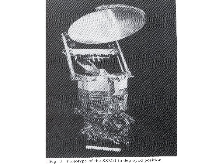
SSM/I Satellite
EOS-PM (AQUA-1) Satellite http: //www. aqua. nasa. gov AMSR-E, Launched May 4, 2002
Data Available from Feb. 2003 onwards Frequencies (GHz) Resolution (km) 6. 6, 10. 65, 18. 7, 76 x 44, 49 x 28, 28 x 16, 23. 8, 36. 5, 89 31 x 18, 14 x 8, 6 x 4
Active Sensor Systems and System Parameters Seasat ERS-1, 2 JERS -1 Radars at SIR-C ENVISAT Radarsat -2 Launch June 1978 July 91 &Apr 95 Feb. 92 Nov. 95 Apr & Oct. 1994 March 1, 2002 2004 Frequency 1. 27 5 5. 3 1. 275 5. 3 1. 2, 5. 3, 9. 8 5. 3 Waveleng. , c m 23. 5 5. 6 23. 5, 5. 6, 3. 1 5. 6 Resolution(m ) 25 30 18 10 100 - 25 30 10 -100 Swath (km) 100 75 35 500 - 15 - 90 150– 1 km 35 – 500 Look anlge 23 23 35 20 - 50 20 - 55 20 - 50 20 – 50 Polarization HH VV HH HH HH, VV, HV HH, VV Looks 4 4 3 1 - 4 -14 4
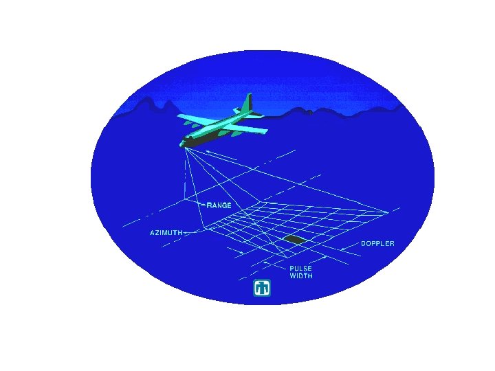
Elements of a Typical Remote Sensing Radar
ERS-1 Satellite with C-band VV SAR system System Parameters Launch: July 91 & Apr ‘ 95 (ERS 2) Frequency : 5. 3 GHz ( =5. 6 cm) Resolution : 30 m Swath : 100 km Look Angle : 230 Polarization: VV Looks : 4
RADARSAT-I System Parameters Frequency : 5. 3 GHz ( =5. 6 cm) Resolution: 10 -100 m Swath : 35 -500 km Look Angle: 20 -500 Polarization : HH Looks : 4 to 14
Future SAR Systems ENVISAT (Launch Date : March 1, 2002)
ENVISAT ASAR Operating Models
First Image from ENVISAT Antarctica Larsen B ice shelf Wide Swath 400 km 150 m resolution March 18, 2002
Incidence Angle Local incidence angle
Slant Range to Ground Range
Geometric Effects Foreshortening Layover Shadow
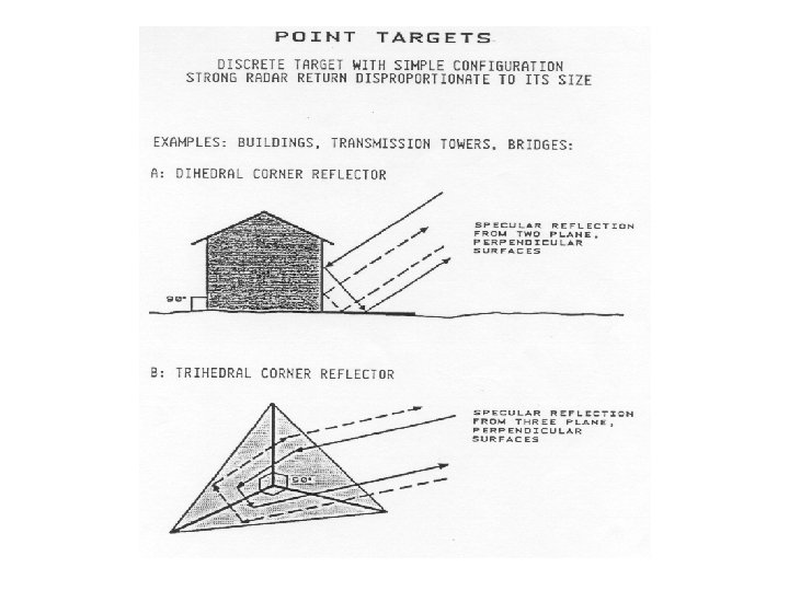
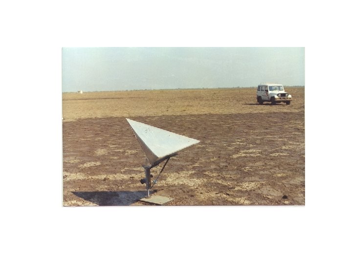
Speckle Reflection, Diffuse scattering Corner Reflector Volume Scattering
Surface Roughness X-band C-band L- 0. 05 smooth 0. 5 rough interm. smooth 1. 5 rough interm. 10. 0 rough
Radarsart 2 2003 HH, VV, HV, VH
Advanced Land Observing Satellite (ALOS) 2004 PALSAR (Phased array SAR) PRISM
Light. SAR (USA & Germany L- and X-band All Polarizations RISAT (Radar Imaging Satellite) C-band in 3 modes
Cryosat Radar Altimeter Mission Determine the variation in the thickness of the Ice sheets to be planned to Launch 2004 Range Resolution 4. 6 cm, accuracy 1 or 2 cm
Indian RISAT SAR Launch year - 2006 Frequency = 5. 35 GHz Resolution HRS 1 -2 m with Swath 10 x 10 km, single/dual polarization FRS-1 mode 3 -6 m with swath 30 km, single/dual polarization FRS-2 model 9 -12, with swath 30 km, Quad polarization MRS/CRS mode 25 - 50 m, with swath 120/240 km, single/quad