Microstrip Patch Antennas EEE 212 EEE 212 MICROSTIP


")


")
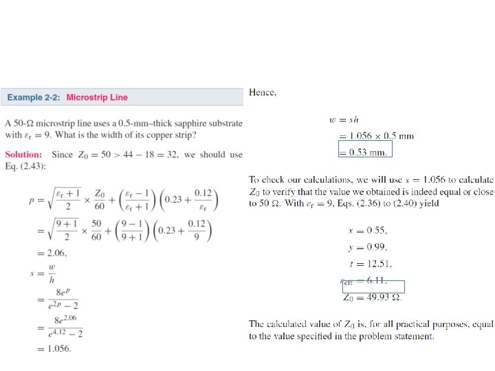
 Inverse process: Given Z 0, find w The solution formulas are")


 • Deschamps –")


- Slides: 89
Microstrip Patch Antennas EEE 212
EEE 212 MICROSTIP LINES
1952
Transmission Lines in ADS • Only the top conductor is shown in ADS – like you are looking at the circuit from the above • Ground plane is normally not shown • Example
Ideal Transmission Lines in ADS Pulldown menu: Tlines-Ideal
Ideal Transmission Lines in ADS Pulldown menu: Tlines-Ideal
Ideal Line S-parameters in ADS
Ideal Line S-parameters in ADS
Open/Shorted Transmission Line (Stub)
Open Transmission Line in parallel with the main line
Quiz: Shorted transmission line in parallel with the main line
Open Transmission Line in parallel with the main line
Microstrip Lines in ADS Pulldown menu: Tlines-Microstrip The length of the line L -> electrical length E of ideal line The width of the line W -> impedance Z of ideal line
How do we calculate width and length of the microstrip line if we know Z, E? And vice versa? • Use Line Calc in ADS • Use equations and write a matlab code
Use Line Calc From Schematic Diagram in ADS Tools-> Line Calc -> Start Line Calc
Quiz: Use Line Calc to find w and l of a microstrip line on RT/Duroid 6002 at 1 GHz. Zo=100 Ohms, l=90 degrees
Lossless Microstrip Line Phase velocity in dielectric: Phase velocity for microstrip: Quasi-TEM
Microstrip (cont. )
Microstrip (cont. ) Inverse process: Given Z 0, find w The solution formulas are based on two numerical fits, defined in terms of the value of Z 0 relative to that of the effective permittivity.
Intro to microwave substrates
EEE 212 QUARTER WAVE TRANSFORMER IMPEDANCE MATCHING
Examples of Matching Networks
Reflection Coefficient
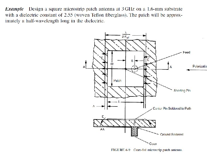
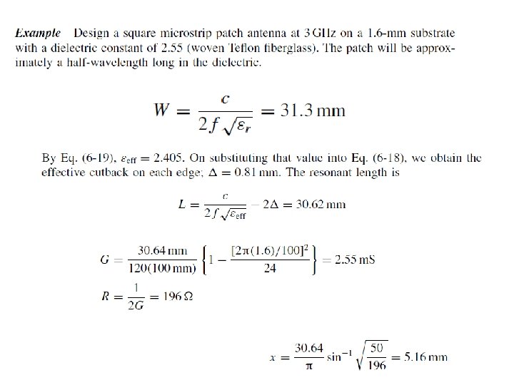
Example
Example
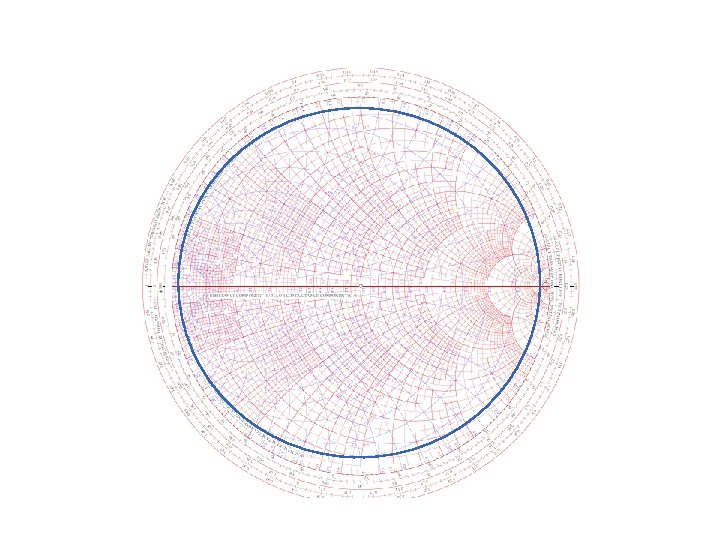
Reflection Coefficient on the Smith Ch
Reflection Coefficient on the Smith Ch
Reading input impedance using Wavelength Toward Generator scale 1. Find the load impedance on SC 2. Draw an SWR circle 3. Draw a line from the center of the SC to the edge to find the reference position on the scale wavelengths toward generator. 4. We add the transmission line length to the reference position 5. We find the position of Zin on the wavelength toward generator scale 6. Draw a line from the center of the circle to the edge of the Smith Chart 7. Where the SWR circle crosses the line ->Zin
Example – Find the input impedance
Example – Find the input impedance
Quarter Wave Transformer
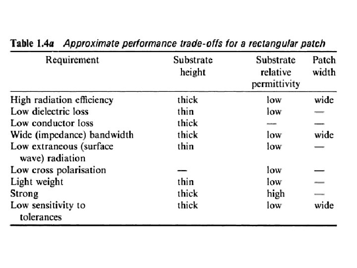
ANTENNA DESIGNER’S CONCERNS
http: //books. google. com/books/about/Handbook_of_Microstrip_Antennas. html? id=Nh. Nk 04 g. Wh 7 AC
http: //books. google. com/books/about/Handbook_of_Microstrip_Antennas. html? id=Nh. Nk 04 g. Wh 7 AC
EEE 212 MICROSTRIP PATCH ANTENNA
http: //books. google. com/books/about/Handbook_of_Microstrip_Antennas. html? id=Nh. Nk 04 g. Wh 7 AC
History • Radiation effects reported by Grieg and Engelmann (50 s) • Deschamps – an array of triangular antennas (50 s) • 70 s new generation of missiles required antennas conforming to the missile surface • In 80 s substrate manufacturing improved – intense R&D focused on patch
Patch Antenna
http: //books. google. com/books/about/Handbook_of_Microstrip_Antennas. html? id=Nh. Nk 04 g. Wh 7 AC
http: //books. google. com/books/about/Handbook_of_Microstrip_Antennas. html? id=Nh. Nk 04 g. Wh 7 AC
EEE 212 FEED
Coax and Strip Line Patch Feeding
Electromagnetic Coupling Feed
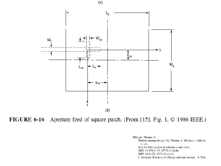
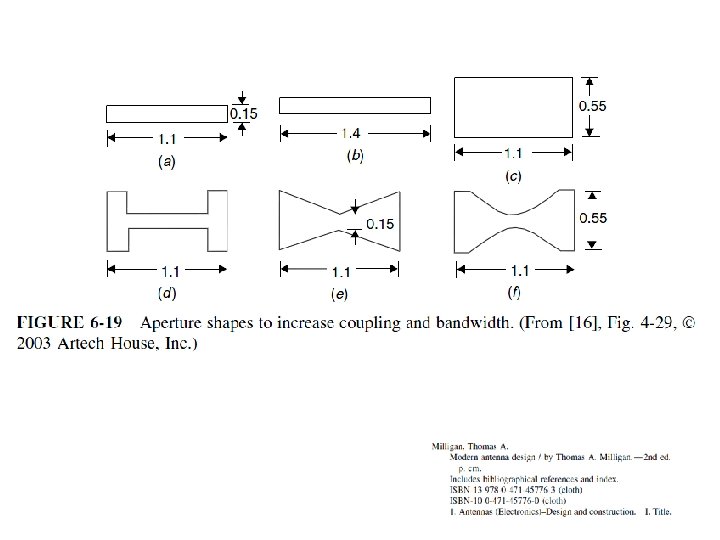
Aperture-Fed Patch
Capacitive Coupled Feed
Inset-Fed Patch
EEE 212 REDUCED SIZE PATCH
Quarter-Wave Patch
Adding a Shorting Pin
Meandering Current Paths
Folding Microstrip Patches
Dual Patch Structure
Patch Antenna Array Feeds
Series Feed Array
EEE 212 PATCH MODELING
Patch Modeling Methods • • Cavity Model Analytical Transmission Line Model Multiple Network Model (MNM) Method of Moments (Mo. M) Numerical Finite-Element Model (FEM) Spectral Domain Technique (SDT) Finite-Difference Time Domain (FTDT)
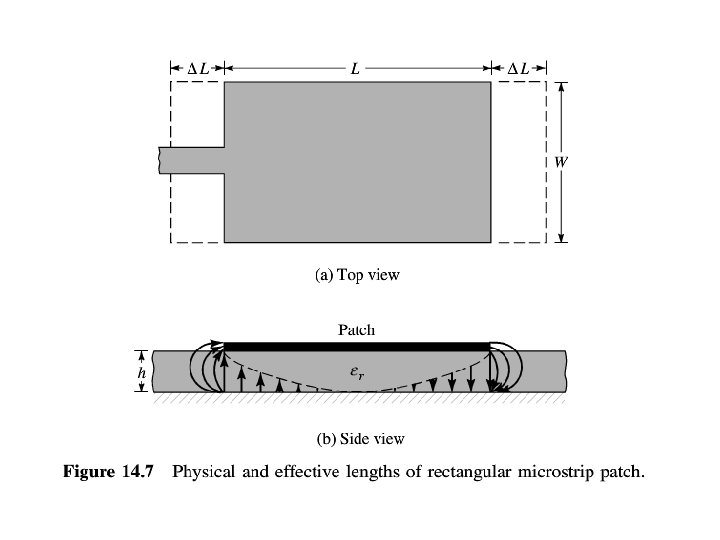
Transmission-line Model • Patch modeled as a section of transmission line • The field varies only along the length (No variation of transverse field ) • Open circuit at the and of the resonator is modeled with equivalent admittance • Easiest and lowest accuracy model
Microstrip Line
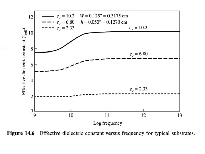
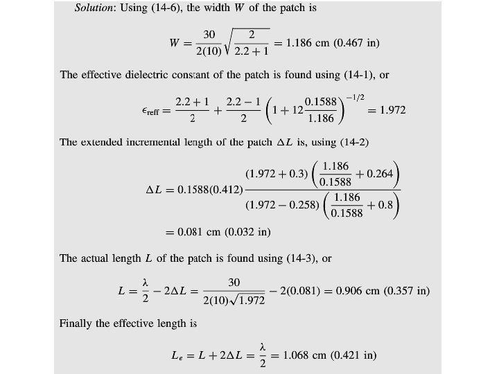
Effective Dielectric Constant
Equation for Length Extension
Frequency of Dominant Mode
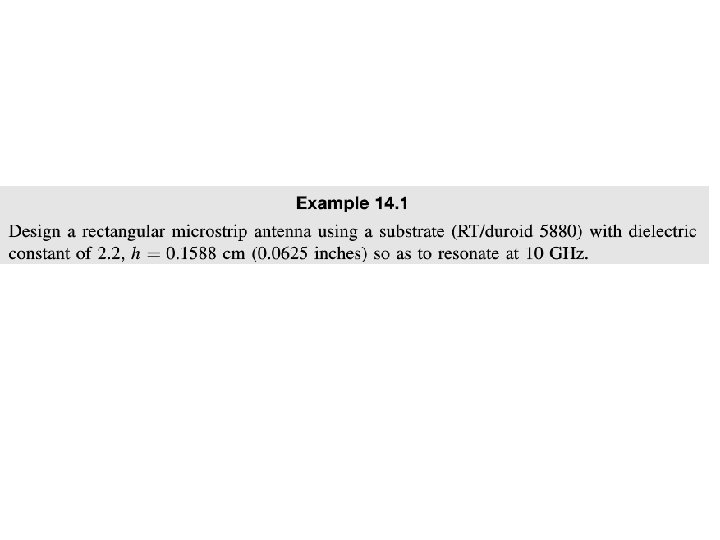
Patch Width
Patch Design Process
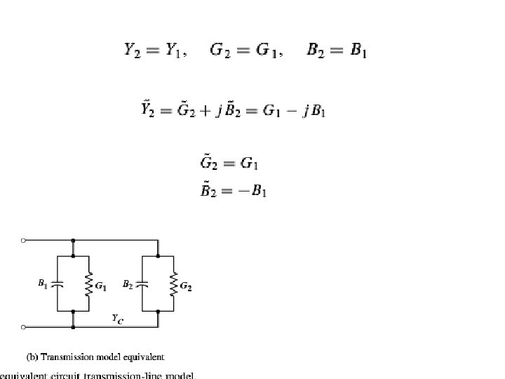
Equivalent Model
Slot Admittance
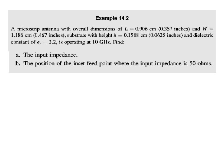
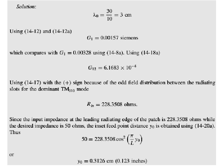
Inset Feed
Input resistance for the inset feed
Input Resistance Seen by Coax