Microscopy Microscopy allows us to view small objects

Microscopy ● ● Microscopy allows us to view small objects as if they we large Simple optical systems were used in early microscopes to view objects in the visible spectrum Today, microscopists employ complex optics, specialized photons, and detectors to image objects in fascinating ways How small can we see?

")
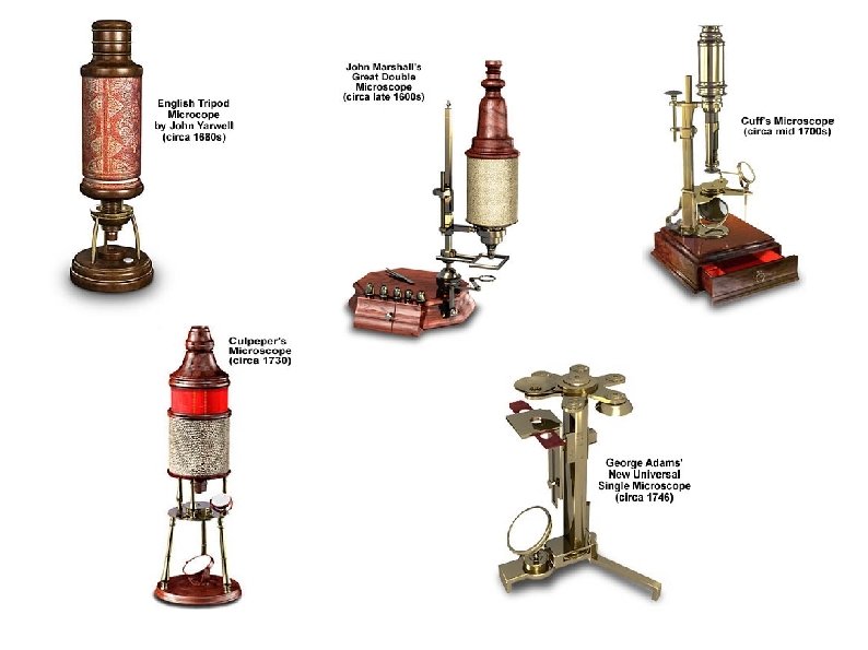
Magnification Optics ● ● Assyrians noted magnifaction of small glass spheres (B. C. ) Ptolemy wrote about magnification and refraction (2 nd century A. D. ) ● Spectacles (1300 A. D. ) ● More detailed investigation in 16 th century ● Galileo is credited with the first biological observations, using the Galilean microscope

Properties of lenses ● Spherical ● Bi-convex ● Bi-concave ● Plano-convex ● Plano-concave

Contrast in Microscopy ● Most thin objects are transparent – ● Need objects as thin as possible, but this can be quite challenging and does not allow easy 3 D analysis Stains can be used to differentiate features
 is about 0. 1 mm at")
Resolution in Microscopes ● ● Human eye (unaided) is about 0. 1 mm at 30 cm Limited by the nature of light – Red light has a wavelength of 700 nm – Violet light has a wavelength of 430 nm – Optical limits are roughly 0. 21 -0. 35 μm

Limitations of early magnifiers ● Distortion ● Imprecise focus ● Chromatic abberation ● Light loss

Simple Microscopes ● ● Simple microscopes consist – a specimen holder – A single lens Disadvantages include – chromatic aberration – Inflexibility in viewing fields

Compound Microscopes ● ● ● Compund microscopes employ two or more lenses Compund microscopes can reduce chromatic aberration and increase flexibility More complex to design

Early Optical Microscopes ● Janssen created a microscope capable of magnifying images between 3 and 10 times ● Bi-convex eyepiece ● Plano-convex objective

Leeuwenhoek's Microscope ● Magnification between 70 x to 250 x ● Small lenses (mm size) ● Resolution of roughly 1 micron

Robert Hooke's Microscope ● Compound design ● Bi-convex objective, eyepiece, and field lens ● Significant spherical and chromatic aberrations ● Internal diapragm ● Ingenious light source
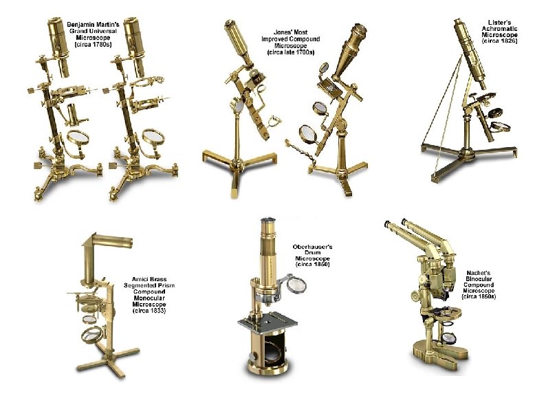
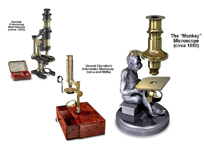
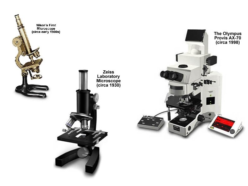
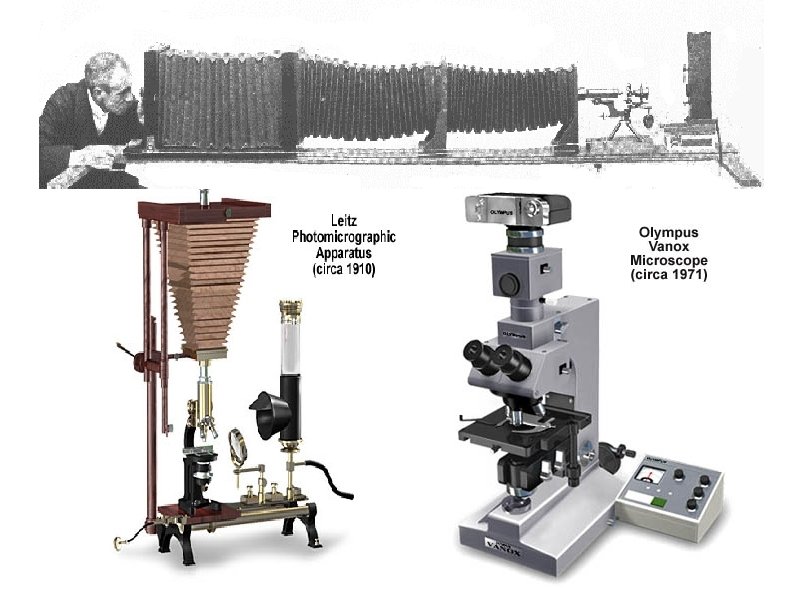

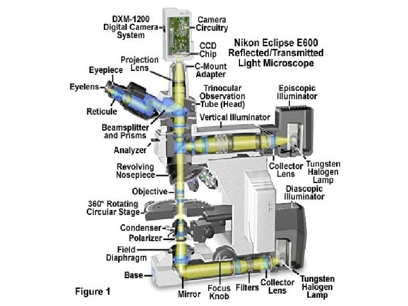
Optical Microscopes ● By 1900, microsopes had reached the limits determined by optical light – Optical theory says smallest clearly objects visible are no smaller than ½ wavelenth of light – Specimen preparation – Optical properties including light polarization were routinely used – Photographic techniques allowed for easy dissemintion of findings

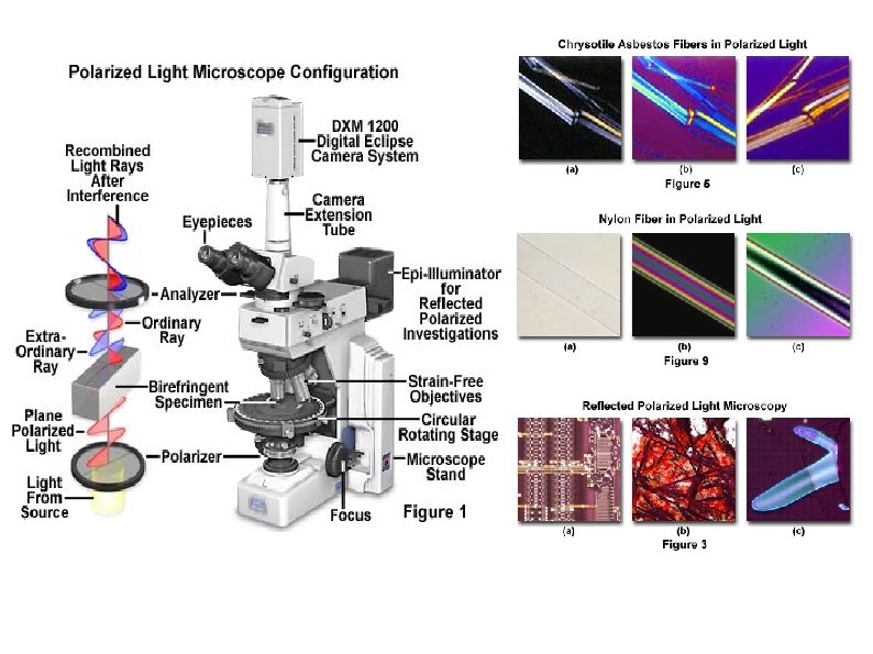
Polarization ● ● In polarizing microscopy, polarized light is reflected by or transmitted through a specimen Some light changes polarization depending on the specimen properties A second polarizing filter removes light unchanged in the specimen Helps distinguish similar materials with – Isotropy (minerals, crystals, glass, ceramics, DNA, etc. )

Phase-contrast ● ● Contrast is enhanced by exploiting sublte differences in refractive indices Similar to polarization A phase shift of the light waves can be introduced which causes interference Allows contrast between living cells and solution by removing background light
 (100 x) A fibroblast in tissue culture visualized with four types")
Chilodonella uncinata (parasite) (100 x) A fibroblast in tissue culture visualized with four types of light microscopy. The image in (A) was obtained by the simple transmission of light through the cell, a technique known as bright-field microscopy. (B) Phase-contrast microscopy; (C) differentialinterference-contrast microscopy; and (D)

Fluorescence Microscopes ● ● ● Contrast is obtained by staining a specimen with a dye (fluorochrome) which absorbs UV light and re-emits it in the visible spectrum Stained objects appear bright with respect to unstained features New techniques allows a green fluorescent protein from a jellyfish to be combined with proteins to undestand cellular function at the protein level.
 Bovine Pulmonary artery endothelium")
Human umbilical vein (120 X) Bovine Pulmonary artery endothelium

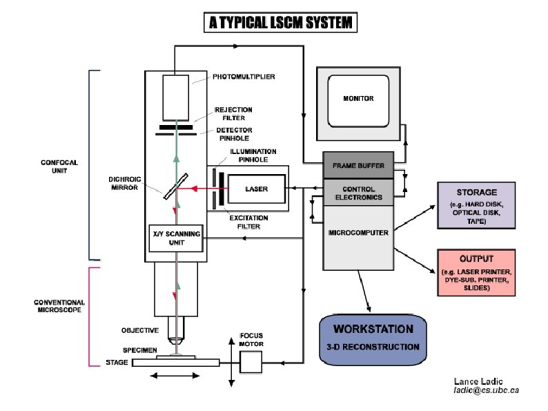
Confocal Scanning Microscopy ● ● Confocal miscropscopy gives a way to preserve three-dimensional structure of a specimen A focussed laser beam sweeps across a specimen at a specific depth Features at other depths have very low contrast An electronic slice is obtained and can be combined with others to study the 3 D nature of the specimen's features
 cells in culture (1, 350 x) 2 micron diameter spheres as")
He. La (cancer) cells in culture (1, 350 x) 2 micron diameter spheres as a volume showing how a 3 D image can be generated. Pollen (40 x)

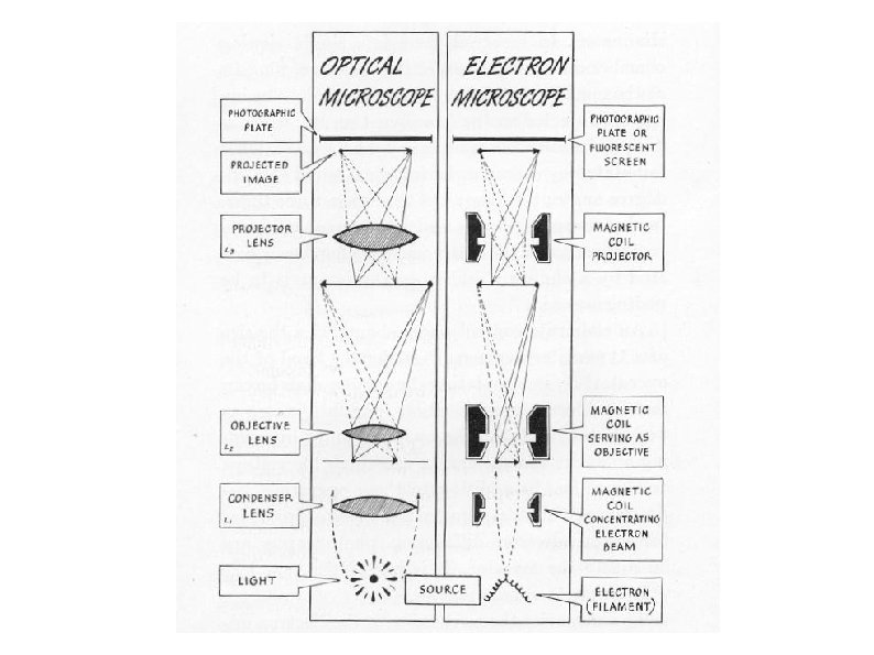
Electron Microscopes ● ● ● Electrons behave just like light photons, except they have a much smaller wavelength (0. 05 nm) than light Electrons can not be directly viewed with the human eye Electrons can only travel in a vacuum Electrons are emitted from a cathode ray gun, interact with the specimen, and are detected Electrons are focussed using magnets

Transmission Electron Microscopes ● ● ● An image is created by measuring the number of electrons passing through the specimen at each image location Contrast is obtained due to differential electron interactions with materials – Large atoms attract and stop more electrons – Small atoms attract fewer electrons A phosphor screen converts the transmitted electrons into visible light

TEM Staining ● ● As in light microscopy, objects can be treated to give more contrast Specimens can be fixed with a heavy metal salt such as Osmium Tetroxide Specimens can be directionally sputter coated with gold or metallic salts The metals absorb more electrons, providing increased contrast in the specimen
 infection in the lung. Clusters of coated")
Transmission Electron Microscope image of cytomegalovirus (CMV) infection in the lung. Clusters of coated virions are present in membrane-limited vesicles. Single, coated virions are also seen in the cisternae of the High magnification transmission electron micrograph of an ultrathin section through a mammalian mitochrondia. The inner and outter mitochondrial membranes as well as the intralumenal space are clearly visible at the periphery of this organelle. Numerous cristae formed by foldings of the inner mitochondrial membrane are

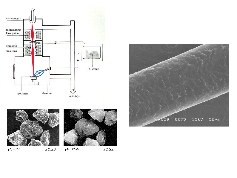
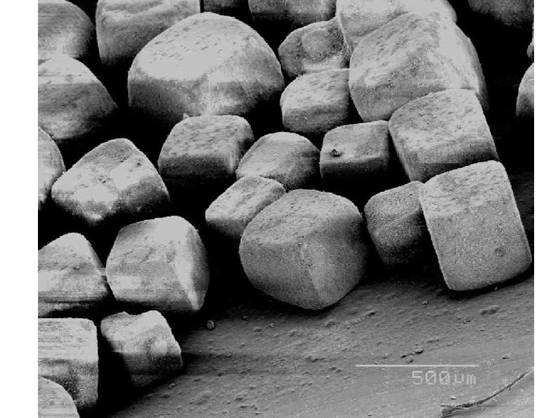
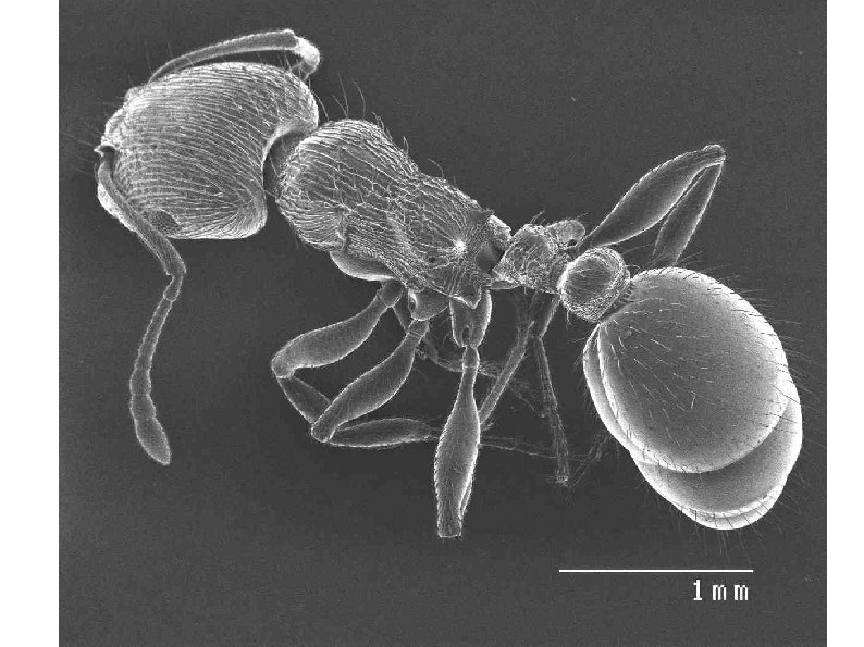
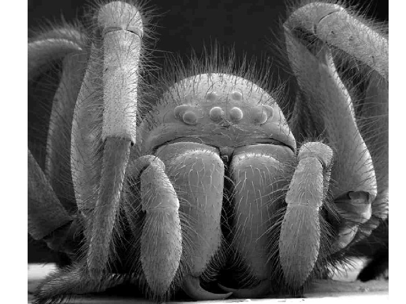
Scanning Electron Microscopes ● Developed in the 1940's ● Perfected in the 1960's ● Produces 3 D images from shadows ● Has a large depth of field ● ● An electron beam is swept across the specimen and the electrons scattered onto a detector An electron beam inside a CRT is swept synchonously with the miscrocope using its intensity to create an image

Scanning Tunneling Microscopes

Acoustical Microscopes

Atomic Force Microscopy


- Slides: 44