Microprogrammed Control Unit Microprogrammed Control Microprogramming is a


- Slides: 28
Micro-programmed Control Unit
Micro-programmed Control • Microprogramming is a method of control unit design in which the control signal selection and the sequencing information is stored in a ROM or RAM called control memory. • A sequence of microinstructions designed to control a specific instruction is called a microprogram.
Micro-programmed Control • For each micro-operation, control unit have to generate a set of control signals • For any micro-operation any control line may be on/off which can be represented by a binary pattern. • Thus a control word is constructed for each micro-operation.
Microprogrammed Control • The control information is stored in a control memory, and the control memory is programmed to initiate the required sequence of microoperations • Adv: Any required change can be done by updating the microprogram in control memory • Disadv: Slow operation
Microprogrammed Control • Microinstruction – The microinstruction specifies one or more microoperations • Microprogram – A sequence of microinstruction • Dynamic microprogramming : Control Memory = RAM – RAM can be used for writing (to change a writable control memory) – Microprogram is loaded initially from an auxiliary memory such as a magnetic disk • Static microprogramming : Control Memory = ROM – Control words in ROM are made permanent during the hardware production.
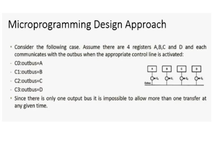
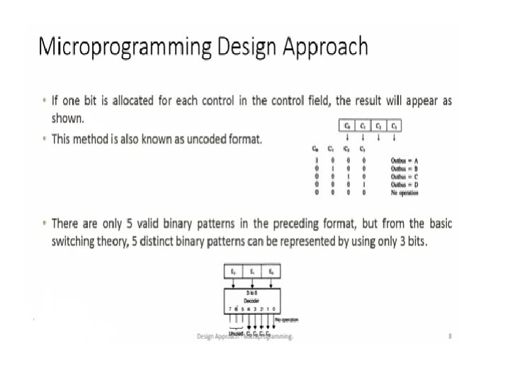
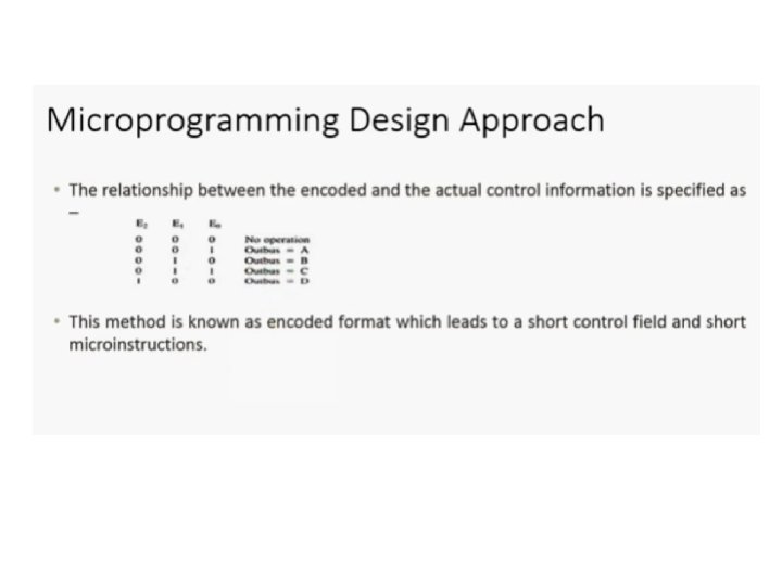
Microprogramming Approach • Generally micro-operations consist of two important fields : – Control Field : indicates which control signals are to be activated – Next Address Field : specify address of next microinstruction • Major Design Effort : Minimize Length of microinstruction.
Microprogramming Approach
Microinstruction Formats • There are two types of formats: – Horizontal Microinstruction – Vertical Microinstruction
Horizontal Microinstruction • For sequencing control word, – an address field is added to it to indicate the next control word to be executed and – a few bits are added to specify the condition for next control word execution
Horizontal Microinstruction Format • Internal CPU control line: one bit for each internal processor control line. • System Bus control line: one bit for each system bus control line.
Horizontal Microinstruction Format • Condition field: indicates condition for taking branch • Address field: address of the next microinstruction to be executed, if the branch is taken.
Interpretation of Micro-instruction 1. To execute this microinstruction, turn on all the control lines indicated by a 1 bit; leave off all control lines indicated by a 0 bit. These control signals will execute one or more micro-operations. 2. If the condition (indicated by the condition bits) is false, execute the next microinstruction in sequence. 3. If the condition is true, execute the next microinstruction pointed by the address field.
Disadv of Horizontal Microinstruction Format • Length of the microinstructions is high • The bits of the micro-program word cannot be used efficiently. i. e. Not all microinstructions allocate useful meanings to all the available fields.
Vertical Microinstruction Format • It uses few bits in the control word • It has the control word with only two fields: – First field is a code – Second field indicates the meaning of the code • It execute simple operations, such as: load, store, add, branch similar to machinelanguage instructions and hence it is also called software microprogramming.
Vertical Microinstruction Format
Disadv of Vertical Microinstruction Format • Speed of execution reduces proportionally with the number of distinct meanings of the code field
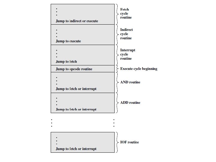
Control Memory Organization • Microinstructions in each routine are to be executed sequentially • Each routing ends with JUMP instruction indicating where to go next • There is a special execute cycle routine to signify which routine is to be executed depending on opcode
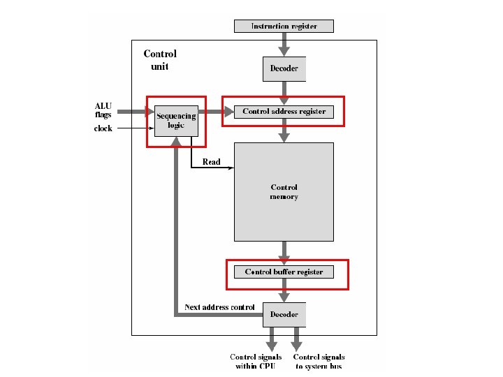
Microprogrammed Control Unit
Microprogrammed Control Unit • It executes a set of microinstructions are stored in control memory • Control Address Register (CAR) – Contains address of next microinstruction to be read – Similar to MAR • Control Buffer Register (CBR) – Contains control word of the currently executing microinstruction • Sequencing Logic Unit – It loads CAR and issues a READ command
Functioning of Micro-programmed CU 1. To execute an instruction, the sequencing logic unit issues a READ command to the control memory. 2. The content of the address specified in CAR is read into CBR 3. CBR generates control signals and next address information for the sequencing logic unit. 4. Sequencing logic unit loads a new address into CAR based on the next-address information from CBR and the ALU flags.
Calculating Next Address • Depending on the value of ALU flags and CBR, one of three decisions is made: • Get the next instruction: – CAR +1 • Jump to a new routine based on a jump microinstruction: – Load the address field of CBR into CAR. • Jump to a machine instruction routine: – Load the CAR based on the opcode in the IR.
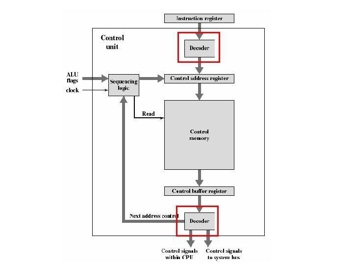
Two Decoders • Upper Decoder: translates the opcode of the IR into CAR • Lower decoder : used only for vertical microinstructions – In a vertical microinstruction, a code is used for each action to be performed and the decoder translates this code into individual control signals