
Microprocessors Chapter 7 80868088 Hardware Specifications prepared by
Microprocessors Chapter 7 8086/8088 Hardware Specifications prepared by Dr. Mohamed A. Shohla
Chapter Overview • Pin Outs and the Pin Functions • Bus Buffering and Latching • Bus Timing Faculty of Electronic Engineering – Dept. of Computer Science & Eng. Microprocessors Course 6 -2
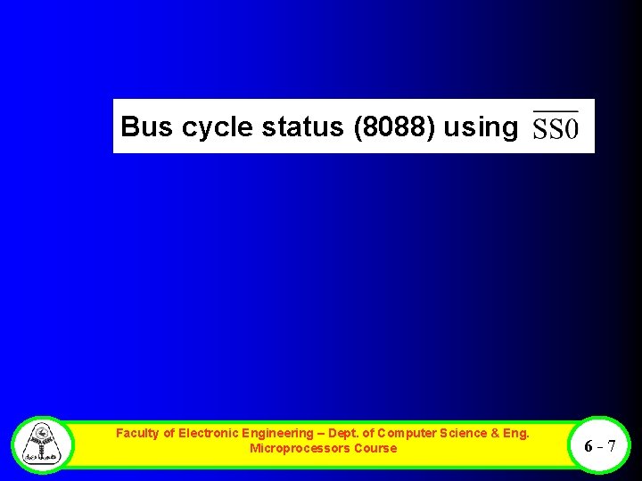
Pin Outs and the Pin Functions • the 8086 is a 16 bit microprocessor with a 16 bit data bus, and the 8088 is a 16 bit microprocessor with an 8 bit data bus. (As the pin outs show, the 8086 has pin connections AD 0 AD 15, and the 8088 has pin connections AD 0 AD 7. ) • Data bus width is therefore the only major difference between these microprocessors. • There is, however, a minor difference in one of the control signals. • The 8086 has an pin, and the 8088 has an pin. • The only other hardware difference appears on Pin 34 of both chips: on the 8088, it is an SSO pin, while on the 8086, it is a pin. Faculty of Electronic Engineering – Dept. of Computer Science & Eng. Microprocessors Course 6 -3
Pin Connections Faculty of Electronic Engineering – Dept. of Computer Science & Eng. Microprocessors Course 6 -4
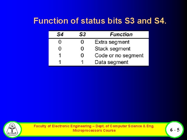
Function of status bits S 3 and S 4. Faculty of Electronic Engineering – Dept. of Computer Science & Eng. Microprocessors Course 6 -5
Minimum Mode Pins Faculty of Electronic Engineering – Dept. of Computer Science & Eng. Microprocessors Course 6 -6
Bus cycle status (8088) using Faculty of Electronic Engineering – Dept. of Computer Science & Eng. Microprocessors Course 6 -7
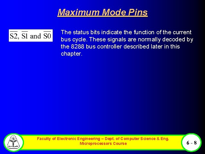
Maximum Mode Pins The status bits indicate the function of the current bus cycle. These signals are normally decoded by the 8288 bus controller described later in this chapter. Faculty of Electronic Engineering – Dept. of Computer Science & Eng. Microprocessors Course 6 -8
Bus Buffering and Latching • Before the 8086/8088 microprocessors can be used with memory or I/O interfaces, their multi plexed buses must be demultiplexed. • This section provides the detail required to demultiplex the buses and illustrates how the buses are buffered for very large systems. Faculty of Electronic Engineering – Dept. of Computer Science & Eng. Microprocessors Course 6 -9
Demultiplexing the Buses of the 8088 • Two 74 LS 373 transparent latches are used to demulti plex the address/data bus connections AD 7 AD 0 and the multiplexed address/status connections A 19/S 6 A 16/S 3. • These transparent latches, which are like wires whenever the address latch enable pin (ALE) becomes a logic 1, pass the inputs to the outputs. After a short time, ALE returns to its logic 0 condition, which causes the latches to remember the inputs at the time of the change to a logic 0. • In this case, A 7 A 0 are stored in the bottom latch and A 19 A 16 are stored in the top latch. Faculty of Electronic Engineering – Dept. of Computer Science & Eng. Microprocessors Course 6 - 10
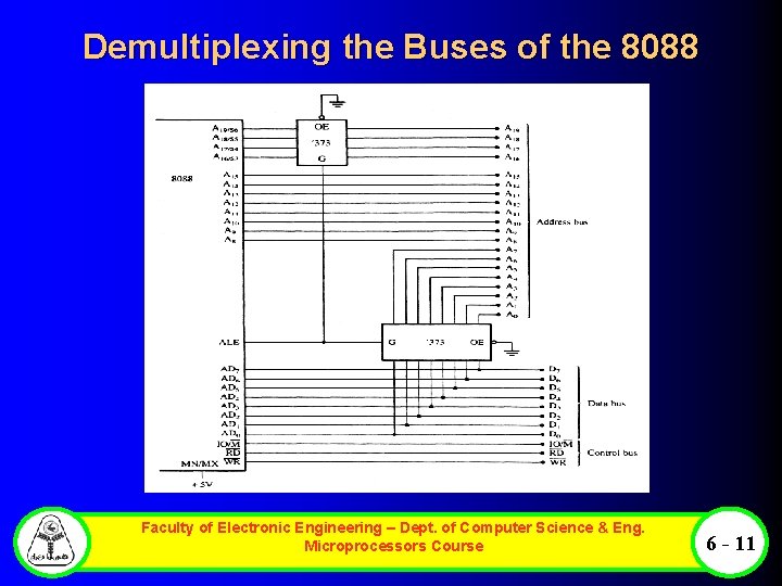
Demultiplexing the Buses of the 8088 Faculty of Electronic Engineering – Dept. of Computer Science & Eng. Microprocessors Course 6 - 11
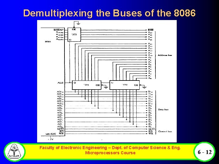
Demultiplexing the Buses of the 8086 Faculty of Electronic Engineering – Dept. of Computer Science & Eng. Microprocessors Course 6 - 12
The Buffered System • • If more than 10 unit loads are attached to any bus pin, the entire 8086 or 8088 system must be buffered. The demultiplexed pins are already buffered by the 74 LS 373 latches, which have been designed to drive the high capacitance buses encountered in microcomputer systems. The buffer's output currents have been increased so that more TTL unit loads may be driven: a logic 0 output provides up to 32 m. A of sink current, and a logic 1 output provides up to 5. 2 m. A of source current. This causes no difficulty unless memory or I/O devices are used, which function at near the maximum speed of the bus. Faculty of Electronic Engineering – Dept. of Computer Science & Eng. Microprocessors Course 6 - 13
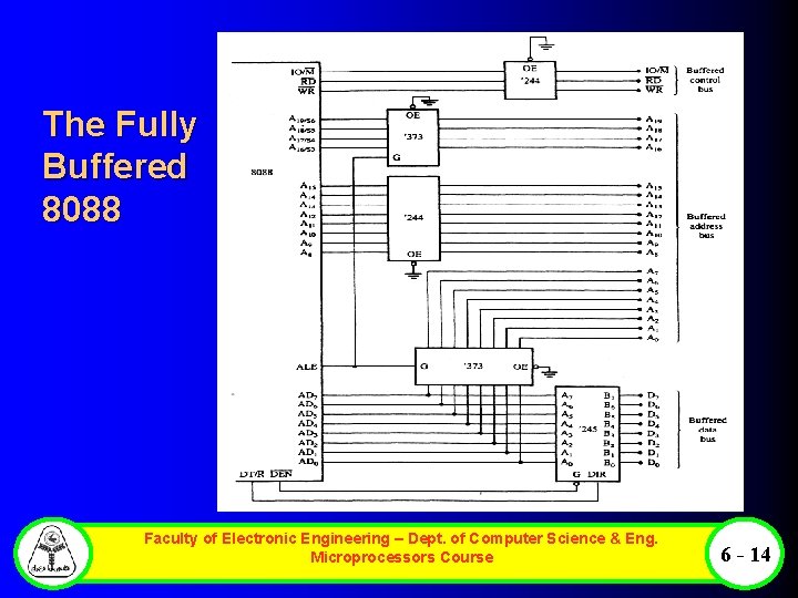
The Fully Buffered 8088 Faculty of Electronic Engineering – Dept. of Computer Science & Eng. Microprocessors Course 6 - 14
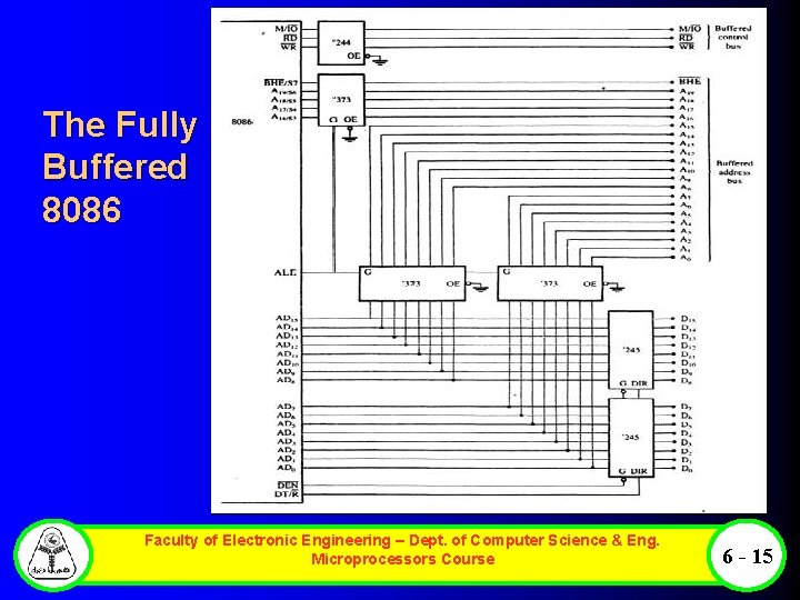
The Fully Buffered 8086 Faculty of Electronic Engineering – Dept. of Computer Science & Eng. Microprocessors Course 6 - 15
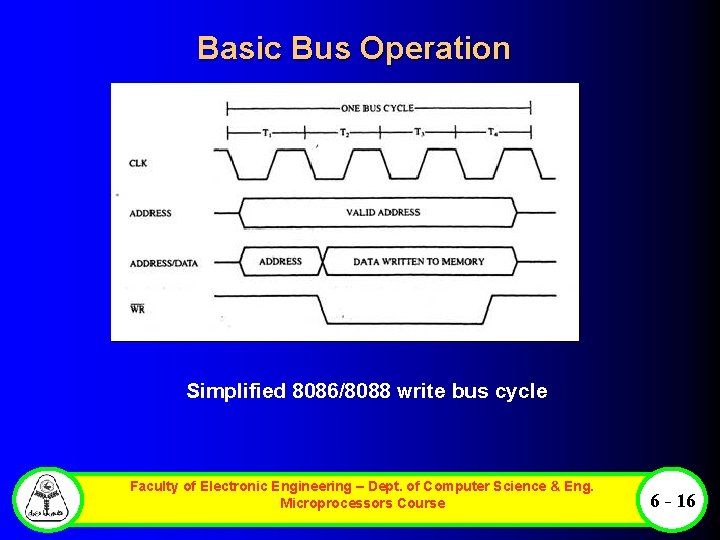
Basic Bus Operation Simplified 8086/8088 write bus cycle Faculty of Electronic Engineering – Dept. of Computer Science & Eng. Microprocessors Course 6 - 16
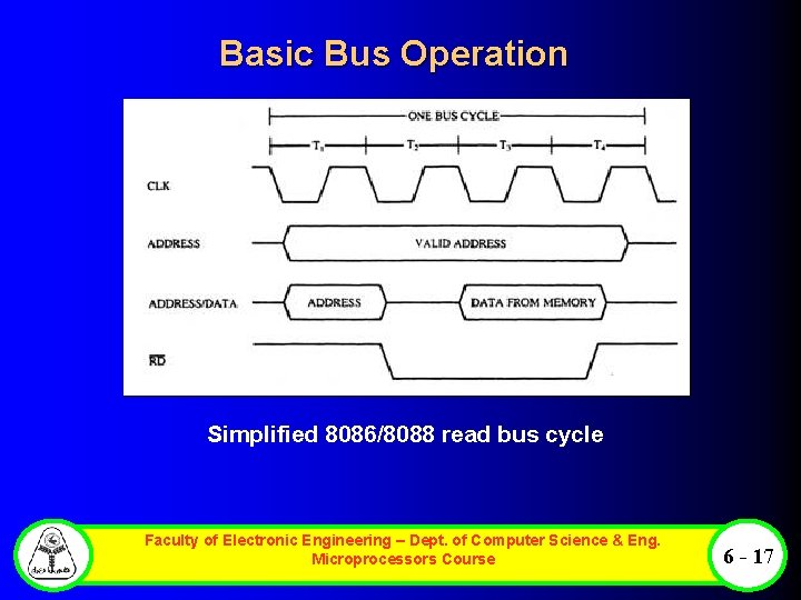
Basic Bus Operation Simplified 8086/8088 read bus cycle Faculty of Electronic Engineering – Dept. of Computer Science & Eng. Microprocessors Course 6 - 17
- Slides: 17