Michelson Interferometer This instrument can produce both types

Michelson Interferometer This instrument can produce both types of interference fringes i. e. , circular fringes of equal inclination at infinity and localized fringes of equal thickness 1

INTERFEROMETER
")
Michelson Interferometer Albert Abraham Michelson (1852 -1931)

Michelson-Morley Experiment In 1878, Michelson thought the detection of motion through the ether might be measurable. In trying to measure the speed of the Earth through the supposed "ether", you could depend upon one component of that velocity being known - the velocity of the Earth around the sun, about 30 km/s. Using a wavelength of about 600 nm, there should be a shift of about 0. 04 fringes as the spectrometer was rotated 360°. Though small, this was well within Michelson's capability. Michelson, and everyone else, was surprised that there was no shift. Michelson's terse description of the experiment: "The interpretation of these results is that there is no displacement of the interference bands. . The result of the hypothesis of a stationary ether is thus shown to be incorrect. " (A. A. Michelson, Am. J. Sci, 122, 120 (1881))

Experimental set up

Michelson Interferometer

Michelson Interferometer

Effective arrangement of the interferometer Circular fringes An observer at the detector looking into B will see M 1, a reflected image of M 2(M 2//) and the images S’ and S” of the source provided by M 1 and M 2. This may be represented by a linear configuration.

Longitudinal section –Circular fringes P rn N q S d O S D

In Young’s double-hole experiment: For small m Radius of nth bright ring

Internal reflection implies that the reflection is from an interface to a medium of lesser index of refraction. External reflection implies that the reflection is from an interface to a medium of higher index of refraction. 11

In Michelson interferometer Order of the fringe: When the central fringe is dark the order of the fringe is As d is increased new fringes appear at the centre and the existing fringes move outwards, and finally move out of the field of view. For any value of d, the central fringe has the largest value of m.

In Michelson interferometer For central dark fringe: The first dark fringe satisfies: For small θ

Radius of nth dark ring: 14

Haidinger Fringe

1. Measurement of wavelength of light Move one of the mirrors to a new position d’ so that the order of the fringe at the centre is changed from mo to m.
")
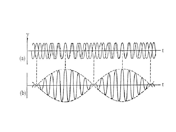
2. Measurement of wavelength separation of a doublet (λ 1 and λ 1+ λ) If the two fringe patterns coincide at the centre: (Concordance) The fringe pattern is very bright 18

Concordance
")
2. Measurement of wavelength separation of a doublet (λ 1 and λ 1+ λ) As d is increased p and q increase by different amounts, with When the bright fringes of λ 1 coincide with the dark fringes of λ 1+ λ, and vice-versa and the fringe pattern is washed away (Discordance).
")
Discordance = (q+1/2)
")
2. Measurement of wavelength separation of a doublet (λ 1 and λ 1+ λ) - Δ can be measured by increasing d 1 to d 2 so that the two sets of fringes, initially concordant, become discordant and are finally concordant again. - If p changes to p+n, and q changes to q+(n-1) we have concordant fringes again. 23

• Measurement of the coherence length of a spectral line • Measurement of thickness of thin transparent flakes • Measurement of refractive index of gases

LIGO - Laser Interferometer Gravitational Wave Observatory To detect Gravitational waves, one of the predictions of Einstein’s General Theory of Relativity When Gravitational waves pass through the interferometer they will displace the mirrors! Hanford Nuclear Reservation, Washington, Livingston, Louisiana Arm length: 4 Km Displacement Sensitivity: 10 -16 cm 25

Fabry-Perot Interferometer 26

Fabry-Perot Interferometer θ 30 o

Multiple Beam Interference 28

Optical Reversibility and Phase Changes on Reflection G. G. Stokes used the principle of optical reversibility to investigate the reflection of light at an interface between two media. The reversibility principle states that If there is no absorption of light, a light ray that is reflected or refracted will retrace its original path if its direction is reversed.

r and t are fractional amplitudes reflected and transmitted respectively According to principle of reversibility, the combined effect of reversing the reflected and transmitted beams should just be the incident beam (in absence of absorption). © SPK

Thin films: multiple beam interference 0 0 0 © SPK 0 0
![Path difference between rays 2 and 1 [(OS + SR)(in film)] – [OM( in](http://slidetodoc.com/presentation_image_h/90cdfe8340b8682c3fefed93935309b4/image-32.jpg "Path difference between rays 2 and 1 [(OS + SR)(in film)] – [OM( in")
Path difference between rays 2 and 1 [(OS + SR)(in film)] – [OM( in air) ] = [(PS + SR)(in film)] – [OM( in air)] = [(PR)(in film)] – [OM( in air)] = μ (PN + NR) – OM = μ (PN) = μ (OP Cos θ) Δ= 2μ d cos θ

CASE - I If 2μ d cos θm = m λ then rays 2, 3, 4, 5, …. are in phase and 1 out of phase. Amplitude of 2+3+4+5 …. 2 4 6 = aotr’t’(1+ r’ +…) 2 = aotr’t’(1/(1 –r’ )) = aotr’t’(1/tt’) = aor’= - aor
 = aor +(- aor) = 0 Amplitude of transmitted beams")
Total reflected Amplitude: 1+(2+3+4+…) = aor +(- aor) = 0 Amplitude of transmitted beams α, β, γ, δ … 2 4 6 = aott’(1+ r’ +…) = ao
 λ then rays 1,")
CASE - II If 2μ d cos θm = (m+1/2) λ then rays 1, 2, 4, 6, … are in phase and 3, 5, … are out of phase. Rays α, γ, … in phase and rays β , δ, … are out of phase

Optical field in reflected beam where : is the incident wave; is the phase arising from the extra optical path length.

Resultant reflected scalar wave If the number of terms of the series approaches infinity, the series converges and the resultant becomes where,

Reflected irradiance

Optical field in transmitted beam

Transmitted irradiance

For Transmitted rays = 2 mπ Path diff. 2μd cos θm = m = (2 m+1)π Path diff. 2μd cos θm = (2 m+1) /2

For Reflected rays

Interference filter

An interference filter is designed for normal incidence of 488 nm light. The refractive index of the spacer is 1. 35. What should be thickness of the spacer for normal incidence of light. It will pass different wavelength if the angle of incidence is not 90 o.

We now introduce Coefficient of Finesse
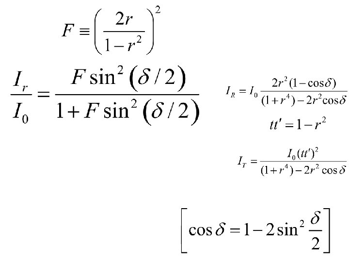

Airy function A Airy function represents the transmitted flux-density distribution. Note: is related to path difference . The complementary [1 - A( )] represents the reflected flux-density distribution.

I 0 d or Multiple beam interference has resulted in redistribution of energy density in comparison to sinusoidal two-beam patter.

IR/I IT/I d or

Variation of intensities with phase d or

Bright fringes Transmitted rays Dark fringes Reflected rays Dark fringes Transmitted rays Bright fringes Reflected rays

Fabry-Perot Interferometer 53

Fabry-Perot Interferometer θ 30 o

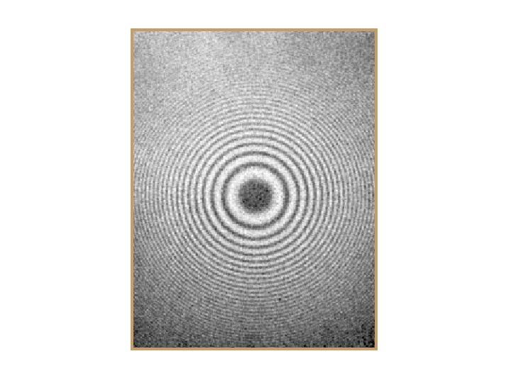
The conditions of interference are precisely those discussed earlier. With =1, the bright fringes in transmission are given by: 2 d cos m= m The radii of the rings are therefore given by the formula obtained in Michelson interferometer i. e. , Rn ≈ D 2 m 2 = D 2 n /d However, there is an essential difference between M. I. and F. P. : One uses a two beam interference while the other uses multiple beam interference. Hence the formula for the intensities and the sharpness of the fringes are quite different.

The intensity is given by: Where F is Coefficient of finesse of the mirror system. F = (2 r/(1 -r 2))2 and we also know that, for bright fringe : 2 d cos m= m What we can conclude from these equations: a)The intensity falls on either side of the maximum. b)The fall in intensity is dictated by the value of the Coefficient of finesse F. c)The Coefficient of finesse is larger for values of the reflection coefficient r approaching unity. Thus very sharp rings are obtained by increasing the polish of the mirrors.

I 0

Transmitted intensity

Full width at half maximum =IT/Io φm

wikipedia

When two mirrors are held fixed and adjusted for parallelism by screwing some sort of spacer, it is said to be an Etalon. A quartz plate polished and metal-coated will also serve as an Etalon (with 1).

Chromatic resolving power - The ability of the spectroscope or the interferometer to separate the components of multiplets is known as chromatic resolving power (CRP). - In a two beam interferometer, like Michelson interferometer and Young’s double slit set-up, the bright fringes are as broad as the dark fringes. The fringes are not sharp. - For good resolution, the bright fringes must be as sharp as possible.

Fabry-Perot fringes Michelson fringes

Doublet separation in Fabry-Perot interferometer

Resolved wavelengths s: separation w: width

Unresolved wavelengths

Barely resolved

Chromatic resolving power of Fabry Perot interferometer - Where, λ is the minimum wavelength interval of a doublet that the instrument is capable of barely resolving. - The criterion for bare resolution is called the Rayleigh criterion. - The smaller the value of λ, the higher is the resolving power of the instrument. Barely resolved Using: 2 d cos θm= mλ ; ( Pabry-Perot - bright fringe in transmission )

FWHM: Angular distance at which the intensity falls to half the peak intensity
 =sin a cos b+ cos a sin b ; Using &")
sin(a+b) =sin a cos b+ cos a sin b ; Using &

Using F 1/2

Sodium doublet λ 1= 589. 0 nm λ 2= 589. 6 nm Δλ= 0. 6 nm λ/Δλ~1000 CRP<1000

Sodium doublet λ 1= 589. 0 nm λ 2= 589. 6 nm Δλ= 0. 6 nm λ/Δλ~1000 CRP ~ 1000

Sodium doublet λ 1= 589. 0 nm λ 2= 589. 6 nm Δλ= 0. 6 nm λ/Δλ~1000 CRP >1000

Sodium doublet λ 1= 589. 0 nm λ 2= 589. 6 nm Δλ= 0. 6 nm λ/Δλ~1000 CRP >> 1000

Sodium doublet λ 1= 589. 0 nm λ 2= 589. 6 nm Δλ= 0. 6 nm λ/Δλ~1000 CRP>>>1000

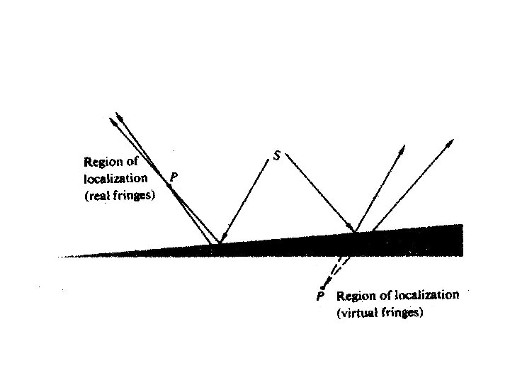
Types of fringes

Interference fringes Real Virtual Localized Non-localized

Real fringe - Can be intercepted on a screen placed anywhere in the vicinity of the interferometer without a condensing lens system. Virtual fringe - Cannot be projected onto a screen without a condensing focusing system. In this case, rays do not converge.

Non-localized fringe - Exists everywhere - Result of point/line source

Localized fringe - Observed over particular surface - Result of extended source

POHL’S INTERFEROMETER Real Non-localized Virtual Localized

Newton’s Ring U<<R & U>>d
- Slides: 84