Michelson Interferometer INTERFEROMETER Michelson Interferometer Albert Abraham Michelson

Michelson Interferometer

INTERFEROMETER
")
Michelson Interferometer Albert Abraham Michelson (1852 -1931)

Experimental set up

M 1 M 2 A

Function of Glass Plate C If C is not used then the path difference will be Will be introduced between the light rays coming from M 1 and M 2. Where t and μ are thickness and refractive index of beam splitter i. e. B. To adjust this path difference a second glass plate C having same thickness, refractive index and at same inclination as beam Splitter is introduced between M 2 and beam splitter. That is C is known as compensating plate.

Working: Phase change on reflection: If glass plate B is semi silvered on back then the two rays AM 1 and AM 2 suffers a phase change of 2π each. Hence a total phase difference between them will be zero. Hence the condition for path difference will be C. I. D. I.

If glass plate B is not semi silvered on back then the ray AM 1 suffers a phase change of π and AM 2 suffers a phase change of 2π each. Hence a total phase difference between them will be π i. e. corresponding path difference will be λ/2. Hence the condition for path difference will be modified as C. I. D. I.

Type of fringes

Effective arrangement of the interferometer Circular fringes S 2 S 1 M ’ 2

Haidinger Fringe
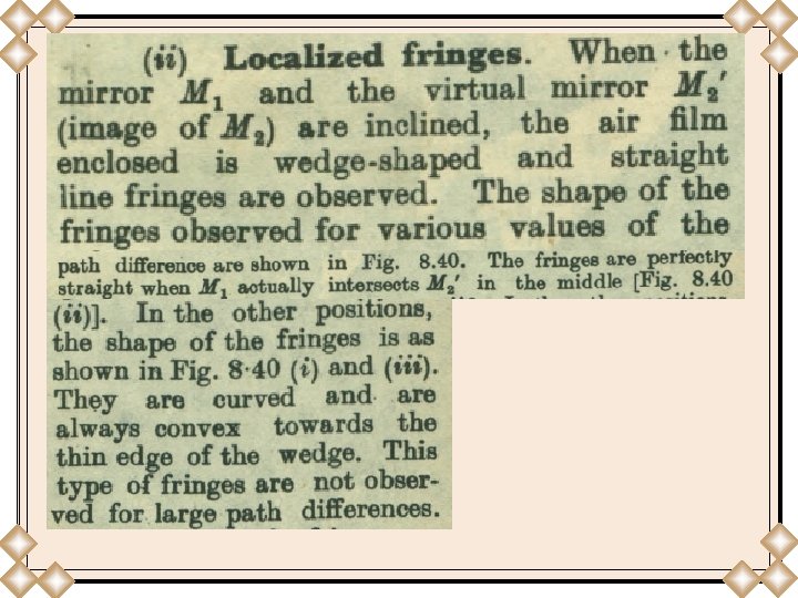
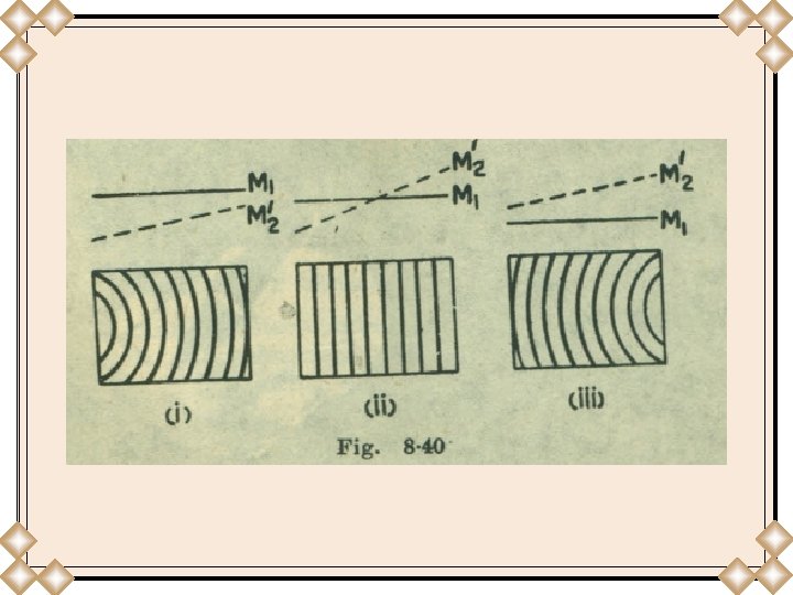

White light fringes To obtain white light fringes M 1 and M 2 are not perpendicular as a result M 1 and M’ 2 are not parallel. Therefore a film of varying thickness is enclosed between M 1 and M’ 2. Thus monochromatic light source (λ) is now replaced by a white light source (λ 1 λ 2 λ 3. . . ). As a result coloured fringes are obtained. The colour with smallest wavelength forms its fringes at the thinner side of the film and as thickness increases the wavelength for fringes also increases. However if M 1 intersects M’ 2 , at the point of intersection the path difference will be zero, resulting a straight line white coloured central fringe. Each side of central white fringe, coloured fringes whose wavelength increases with the thickness of the film are obtained.

However when the thickness becomes very large more than one colour forms its fringes at the same point. As a result overlapping takes place, so all colours forms their fringes at the same point. Thus we have uniform illumination i. e. white region. • Order of the fringe • Formation of both real and virtual fringes
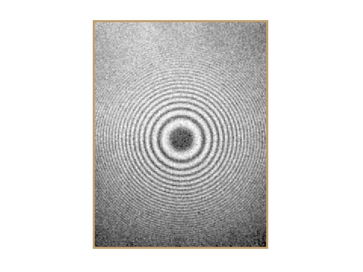

1. Measurement of wavelength of light At centre i. e. each time when a mirror M 1 is moved by a distance of λ/2, the order at the centre will increase by one i. e. new fringe is obtained.

Therefore time M 1 is moved by λ/2 , one new fringe will appear from the centre. The positions of mirror M 1 is recorded with the scale attached to M 1. If the initial and final positions are x 1 and x 2 respectively. Then the distance by which M 1 is moved If during this movement N new fringes will appear from the centre, then

• Measurement of the coherence length of a spectral line • Formation of straight white light fringes • Measurement of thickness of thin transparent flakes • Measurement of refractive index of gases • Standardization of meter scale

1. Optics Author: Eugene Hecht 2. Optics Author: Ajoy Ghatak Edition 4 th Article 15. 11 page 15. 22
- Slides: 20