
MICE Spectrometer Solenoid Electrical System Soren Prestemon FNAL
- Slides: 38
MICE Spectrometer Solenoid Electrical System Soren Prestemon FNAL, Dec. 3, 2015 Most of the content has been gathered from work/slides by John Joseph, Heng Pan, Vladimir Kashikin
Outline • General electrical layout – Original design – Modifications in the last years • Magnet protection design – Review of protection strategy – Strengths and weaknesses • Modeling of protection scenarios – Model assumptions and limitations 12/03/15 Soren Prestemon 2
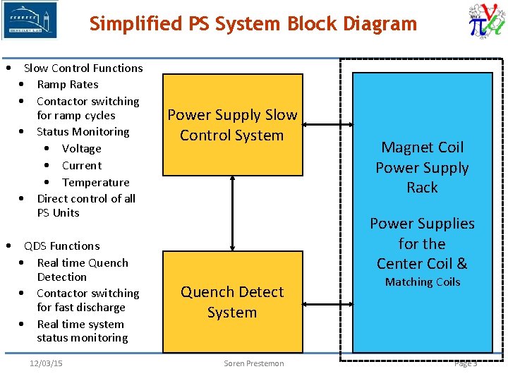
Simplified PS System Block Diagram • Slow Control Functions • Ramp Rates • Contactor switching for ramp cycles • Status Monitoring • Voltage • Current • Temperature • Direct control of all PS Units • QDS Functions • Real time Quench Detection • Contactor switching for fast discharge • Real time system status monitoring 12/03/15 Power Supply Slow Control System Magnet Coil Power Supply Rack Power Supplies for the Center Coil & Quench Detect System Soren Prestemon Matching Coils Page 3
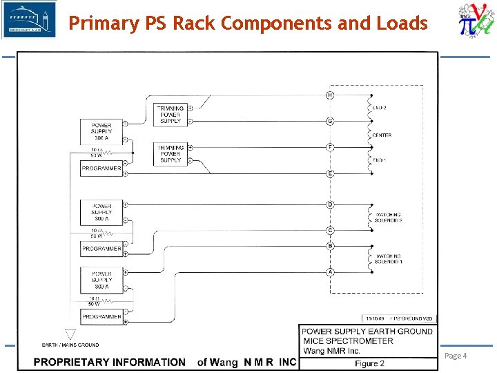
Primary PS Rack Components and Loads 12/03/15 Soren Prestemon Page 4
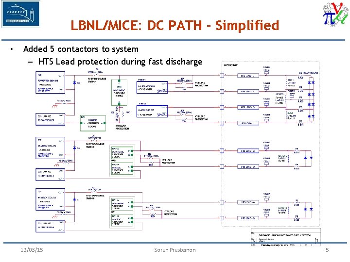
LBNL/MICE: DC PATH - Simplified • Added 5 contactors to system – HTS Lead protection during fast discharge 12/03/15 Soren Prestemon 5
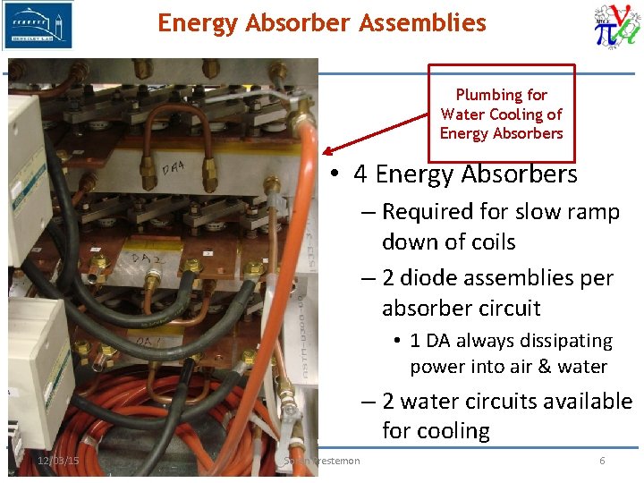
Energy Absorber Assemblies Plumbing for Water Cooling of Energy Absorbers • 4 Energy Absorbers – Required for slow ramp down of coils – 2 diode assemblies per absorber circuit • 1 DA always dissipating power into air & water – 2 water circuits available for cooling 12/03/15 Soren Prestemon 6
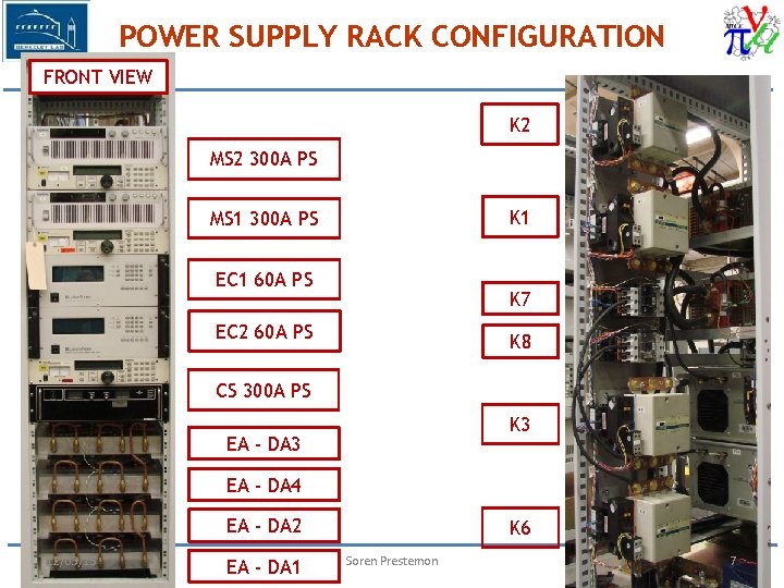
POWER SUPPLY RACK CONFIGURATION FRONT VIEW K 2 MS 2 300 A PS K 1 MS 1 300 A PS EC 1 60 A PS K 7 EC 2 60 A PS K 8 CS 300 A PS K 3 EA - DA 4 EA - DA 2 12/03/15 EA - DA 1 K 6 Soren Prestemon 7
Summary of Changes Implemented @ LBL • Redesigned system to improve HTS Lead protection – Additional contactors to isolate coils from power supplies during fast ramp down and enable in-cryo coil protection – Adding 2 nd Solid State Relay to handle increased Contactor pickup current • Reconfigured rack to optimize DC cabling – Improved physical separation of AC and DC wires – All Contactors physically close to associated supplies • Moved all AC wiring above water cooling circuits • Replacing 15 VDC PS with 24 VDC PS for interlock circuits • Replaced all control and monitoring wiring – Bundled twisted pair 12/03/15 Soren Prestemon 8
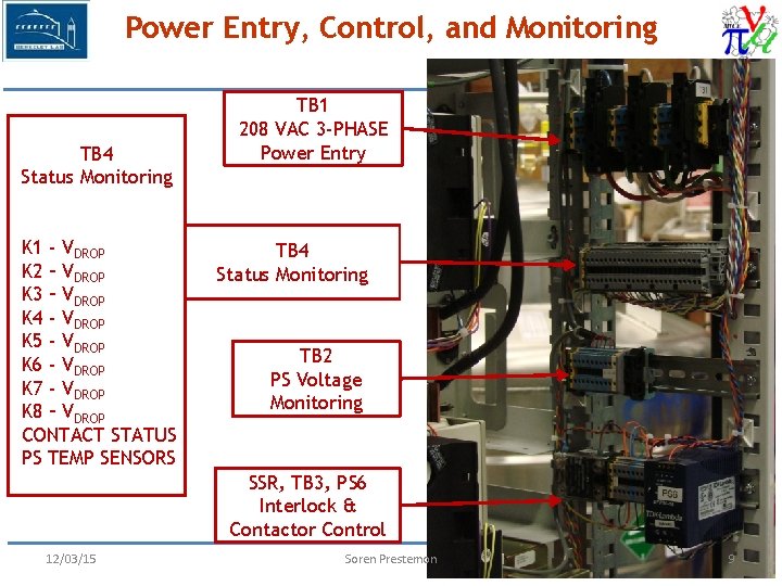
Power Entry, Control, and Monitoring TB 4 Status Monitoring K 1 - VDROP K 2 – VDROP K 3 – VDROP K 4 - VDROP K 5 - VDROP K 6 - VDROP K 7 - VDROP K 8 – VDROP CONTACT STATUS PS TEMP SENSORS TB 1 208 VAC 3 -PHASE Power Entry TB 4 Status Monitoring TB 2 PS Voltage Monitoring SSR, TB 3, PS 6 Interlock & Contactor Control 12/03/15 Soren Prestemon 9
Magnet Protection 12/03/15 Soren Prestemon 10
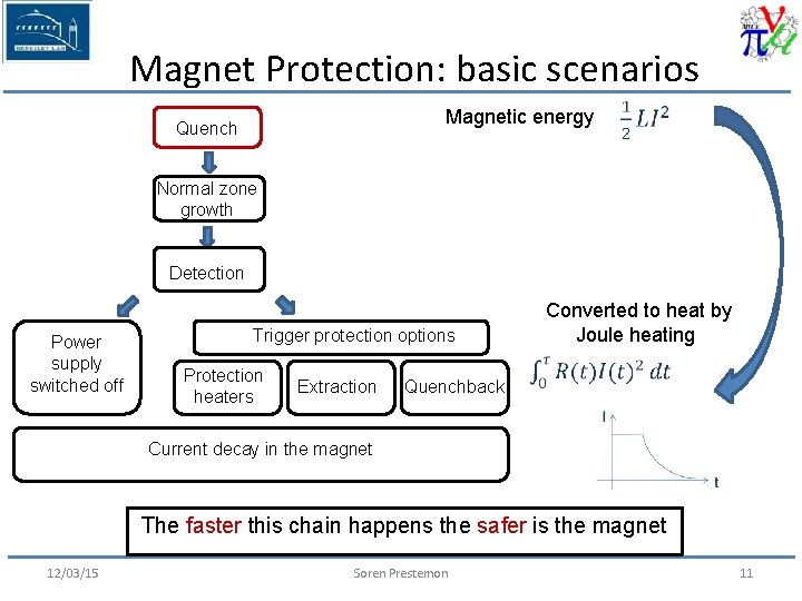
Magnet Protection: basic scenarios Magnetic energy Quench Normal zone growth Detection Power supply switched off Trigger protection options Protection heaters Extraction Converted to heat by Joule heating Quenchback Current decay in the magnet The faster this chain happens the safer is the magnet 12/03/15 Soren Prestemon 11
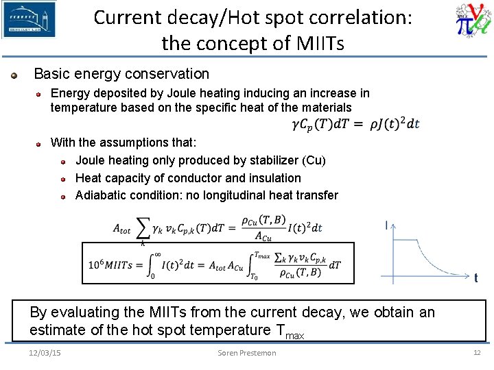
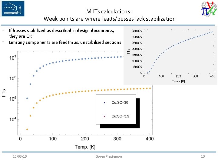
Current decay/Hot spot correlation: the concept of MIITs Basic energy conservation Energy deposited by Joule heating inducing an increase in temperature based on the specific heat of the materials With the assumptions that: Joule heating only produced by stabilizer (Cu) Heat capacity of conductor and insulation Adiabatic condition: no longitudinal heat transfer By evaluating the MIITs from the current decay, we obtain an estimate of the hot spot temperature Tmax 12/03/15 Soren Prestemon 12
MIITs calculations: Weak points are where leads/busses lack stabilization • • If busses stabilized as described in design documents, they are OK Limiting components are feedthrus, unstabilized sections 12/03/15 Soren Prestemon 13
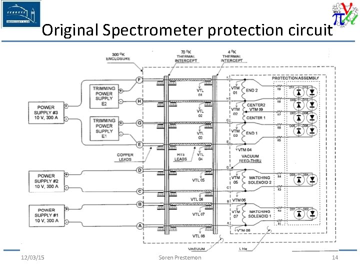
Original Spectrometer protection circuit 12/03/15 Soren Prestemon 14
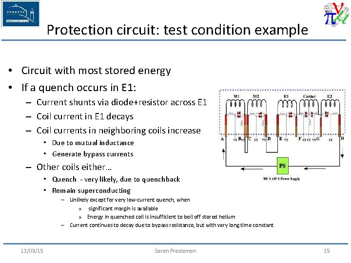
Protection circuit: test condition example • Circuit with most stored energy • If a quench occurs in E 1: – Current shunts via diode+resistor across E 1 – Coil current in E 1 decays – Coil currents in neighboring coils increase • Due to mutual inductance • Generate bypass currents – Other coils either… • Quench - very likely, due to quenchback • Remain superconducting – Unlikely except for very low-current quench, when » significant margin is available » Energy in quenched coil is insufficient to boil off stored helium – Current continues to decay due to bypass resistance, but with very long time constant 12/03/15 Soren Prestemon 15
Review of Spectrometer protection circuit • System is passive – No “need” to trigger any circuitry – Bypass resistors allow each coil / coil section to decay at their own speed – Reduces hot –spot temperatures, peak voltages • But… – No direct ability to initiate quenches(!) – Bypass resistors cannot serve as full energy absorbers • They “buy us some time” for quenchback to occur • What we want: – A system that protects coils well during quenches (e. g. training) – A system that avoids damage to the cold mass during serious faults 12/03/15 Soren Prestemon 16
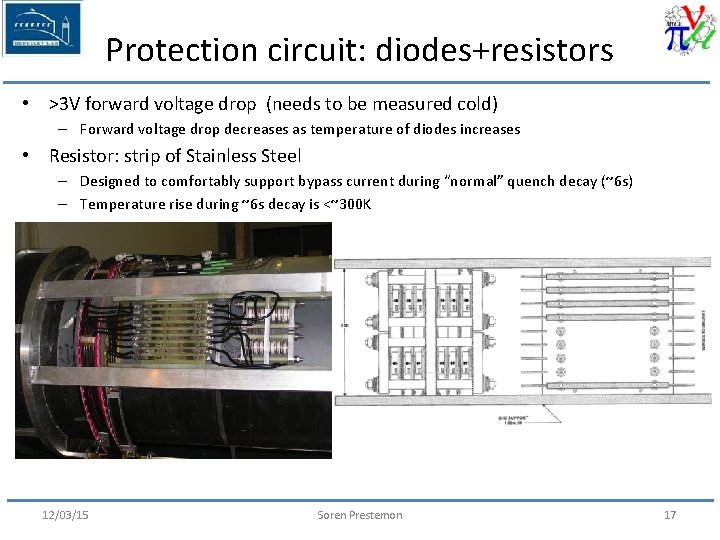
Protection circuit: diodes+resistors • >3 V forward voltage drop (needs to be measured cold) – Forward voltage drop decreases as temperature of diodes increases • Resistor: strip of Stainless Steel – Designed to comfortably support bypass current during “normal” quench decay (~6 s) – Temperature rise during ~6 s decay is <~300 K 12/03/15 Soren Prestemon 17
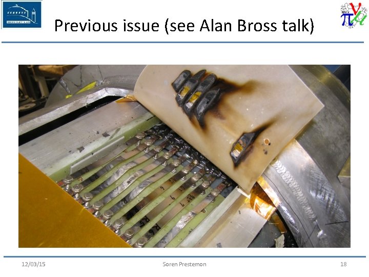
Previous issue (see Alan Bross talk) 12/03/15 Soren Prestemon 18
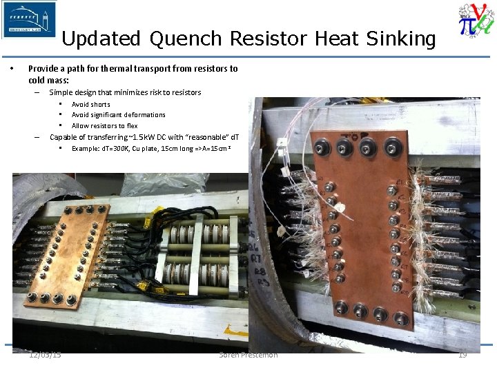
Updated Quench Resistor Heat Sinking • Provide a path for thermal transport from resistors to cold mass: – – Simple design that minimizes risk to resistors • Avoid shorts • Avoid significant deformations • Allow resistors to flex Capable of transferring ~1. 5 k. W DC with “reasonable” d. T • Example: d. T=300 K, Cu plate, 15 cm long =>A=15 cm 2 12/03/15 Soren Prestemon 19
HTS leads • Protection concept: – First: avoid quench by providing margin! • No energizing until high-end temp. sufficiently low – Second: trigger spin-down if issue arises • Interlock PS to high-end temperature • Interlock PS to voltage drop – Third: make access to HTS leads “reasonable” • And design protection to avoid damage to cold-mass in case of such faults 12/03/15 Soren Prestemon 20
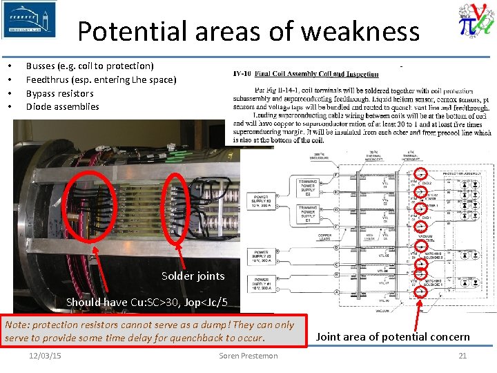
Potential areas of weakness • • Busses (e. g. coil to protection) Feedthrus (esp. entering Lhe space) Bypass resistors Diode assemblies Solder joints Should have Cu: SC>30, Jop<Jc/5 Note: protection resistors cannot serve as a dump! They can only serve to provide some time delay for quenchback to occur. 12/03/15 Soren Prestemon Joint area of potential concern 21
Quench modeling 12/03/15 Soren Prestemon 22
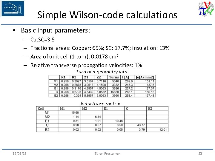
Simple Wilson-code calculations • Basic input parameters: – – Cu: SC=3. 9 Fractional areas: Copper: 69%; SC: 17. 7%; insulation: 13% Area of unit cell (1 turn): 0. 0178 cm 2 Relative transverse propagation velocities: 1% Turn and geometry info Inductance matrix 12/03/15 Soren Prestemon 23
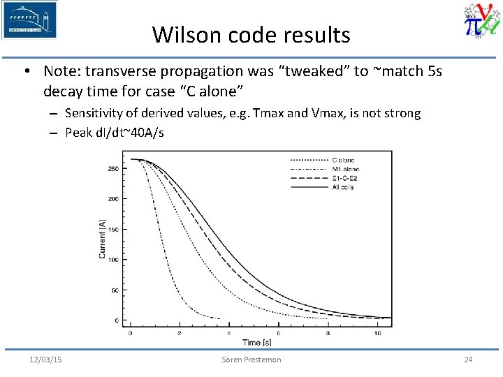
Wilson code results • Note: transverse propagation was “tweaked” to ~match 5 s decay time for case “C alone” – Sensitivity of derived values, e. g. Tmax and Vmax, is not strong – Peak d. I/dt~40 A/s 12/03/15 Soren Prestemon 24
3 D simulations • Limitations of “Wilson code” simulation: – Does not consider mutual coupling and full electric circuit – Does not take into account quenchback from mandrel heating – Does not provide means of determining turn-to-turn or layer-to-layer voltages • Vector Field Quench module: – Provides for mutual coupling and full electric circuit – Provides for quenchback from mandrel heating – Can use “Wilson-code” for validation on simple system (e. g. single coil with no quenchback) 12/03/15 Soren Prestemon 25
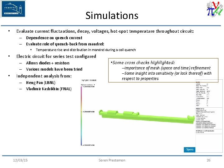
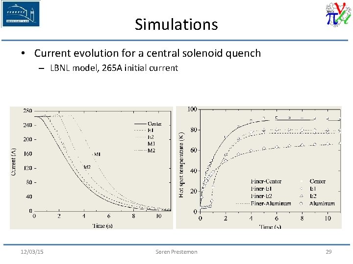
Simulations • Evaluate current fluctuations, decay, voltages, hot-spot temperature throughout circuit: – Dependence on quench current – Evaluate role of quench-back from mandrel: • • Temperature rise and distribution in mandrel during a coil quench Electric circuit for series test configured – Allows diodes + resistors – Various models have been tried • Independent analysis from: – Heng Pan (LBNL) – Vladimir Kashikhin (FNAL) 12/03/15 • Some cross checks highlighted: –Importance of mesh (space and time) refinement –Some insight into sensitivity (or lack thereof) with respect to properties Soren Prestemon 26
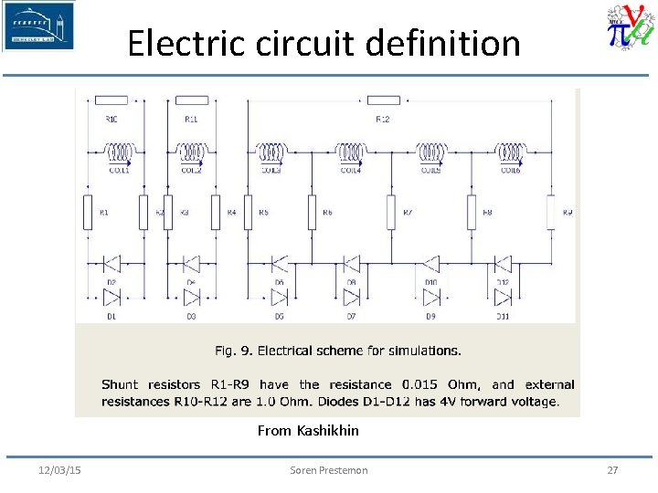
Electric circuit definition From Kashikhin 12/03/15 Soren Prestemon 27
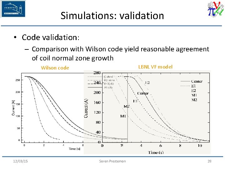
Simulations: validation • Code validation: – Comparison with Wilson code yield reasonable agreement of coil normal zone growth LBNL VF model Wilson code 12/03/15 Soren Prestemon 28
Simulations • Current evolution for a central solenoid quench – LBNL model, 265 A initial current 12/03/15 Soren Prestemon 29
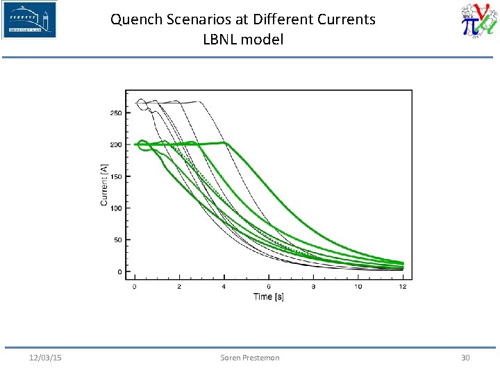
Quench Scenarios at Different Currents LBNL model 12/03/15 Soren Prestemon 30
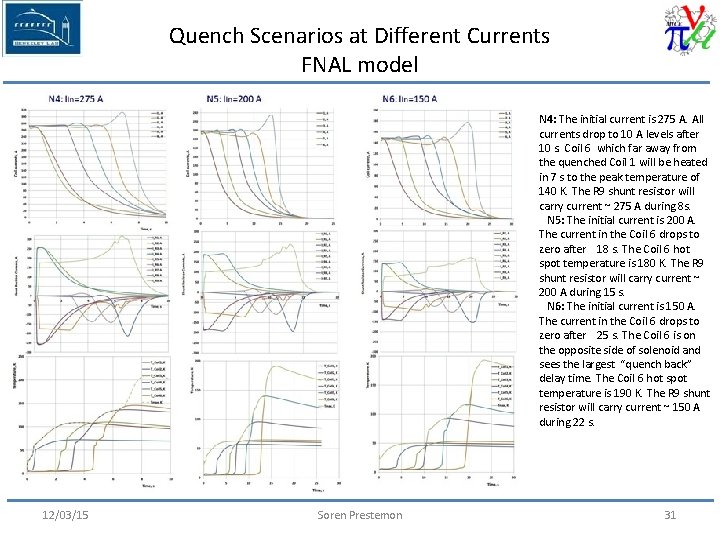
Quench Scenarios at Different Currents FNAL model N 4: The initial current is 275 A. All currents drop to 10 A levels after 10 s. Coil 6 which far away from the quenched Coil 1 will be heated in 7 s to the peak temperature of 140 K. The R 9 shunt resistor will carry current ~ 275 A during 8 s. N 5: The initial current is 200 A. The current in the Coil 6 drops to zero after 18 s. The Coil 6 hot spot temperature is 180 K. The R 9 shunt resistor will carry current ~ 200 A during 15 s. N 6: The initial current is 150 A. The current in the Coil 6 drops to zero after 25 s. The Coil 6 is on the opposite side of solenoid and sees the largest “quench back” delay time. The Coil 6 hot spot temperature is 190 K. The R 9 shunt resistor will carry current ~ 150 A during 22 s. 12/03/15 Soren Prestemon 31
Quench Scenarios at Different Currents: Model differences • Main differences: – FNAL model yields longer delay between quenchback of coils further away – FNAL model yields higher hotspot temperatures • Expected sources of differences: – FNAL model needs further time-step reduction – FNAL model includes insulation layer All models assumed contact between coil and mandrel at all interfaces; this may not be valid under all operating conditions. 12/03/15 Soren Prestemon 32
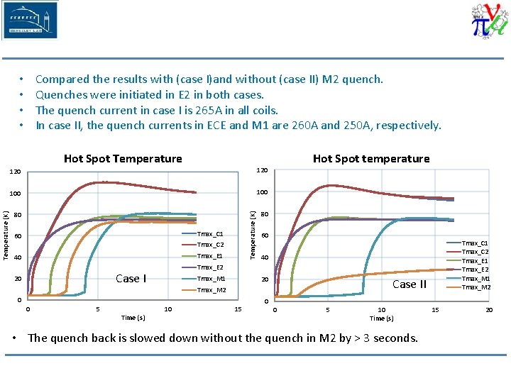
Compared the results with (case I)and without (case II) M 2 quench. Quenches were initiated in E 2 in both cases. The quench current in case I is 265 A in all coils. In case II, the quench currents in ECE and M 1 are 260 A and 250 A, respectively. • • 120 100 80 80 Temperature (K) Hot Spot Temperature Tmax_C 1 60 Tmax_C 2 Tmax_E 1 40 60 40 Tmax_M 1 20 Case II Tmax_M 2 0 0 5 Time (s) Tmax_C 1 Tmax_C 2 Tmax_E 1 Tmax_E 2 Tmax_M 1 Tmax_M 2 Tmax_E 2 Case I 20 Hot Spot temperature 10 15 0 0 5 10 Time (s) • The quench back is slowed down without the quench in M 2 by > 3 seconds. 15 20
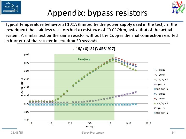
Appendix: bypass resistors Typical temperature behavior at 100 A (limited by the power supply used in the test). In the experiment the stainless resistors had a resistance of ~0. 04 Ohm, twice that of the actual system. A similar test on the same resistor without the Copper thermal connection resulted in burnout of the resistor in less than 30 seconds. 12/03/15 Soren Prestemon 34
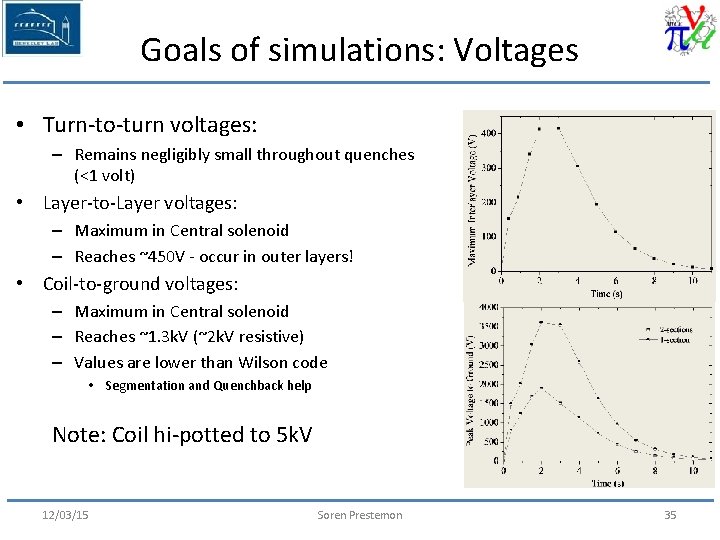
Goals of simulations: Voltages • Turn-to-turn voltages: – Remains negligibly small throughout quenches (<1 volt) • Layer-to-Layer voltages: – Maximum in Central solenoid – Reaches ~450 V - occur in outer layers! • Coil-to-ground voltages: – Maximum in Central solenoid – Reaches ~1. 3 k. V (~2 k. V resistive) – Values are lower than Wilson code • Segmentation and Quenchback help Note: Coil hi-potted to 5 k. V 12/03/15 Soren Prestemon 35
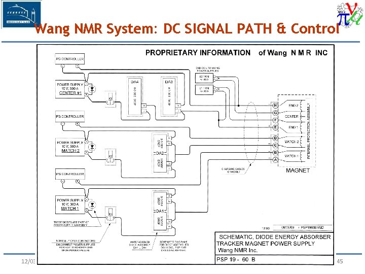
Wang NMR System: DC SIGNAL PATH & Control 12/03/15 Soren Prestemon Page 45
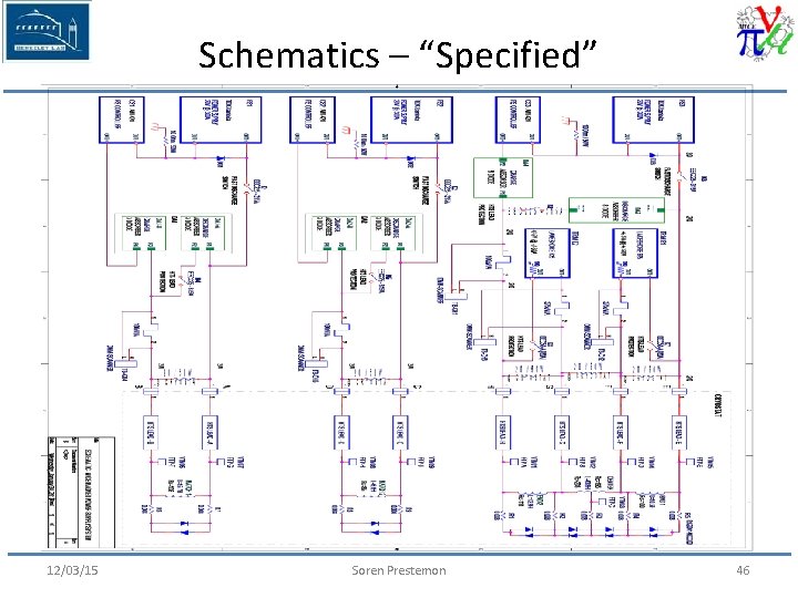
Schematics – “Specified” 12/03/15 Soren Prestemon 46
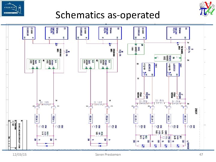
Schematics as-operated 12/03/15 Soren Prestemon 47