
Method of Characteristics Minimum Length Nozzle and Aerospike

















- Slides: 76
Method of Characteristics, Minimum Length Nozzle, and Aerospike Nozzle Contour Design Stephen A. Whitmore Mechanical and Aerospace Engineering Department (Not in Sutton and Biblarz) MAE 5540 - Propulsion Systems 1
The NASA Need? (1) NASA RFI Solicitation Number NNC 09 Z 005: MARS ASCENT VEHICLE TECHNOLOGIES FOR DEVELOPMENT, DUE JAN 30, 2009. • NASA’s In-Space Propulsion Technology (ISPT) project has been assigned the responsibility of developing propulsion technologies needed to enable future sample return missions. • In recognition of the high interest of the science community in the return of samples from Mars the ISPT project, working in conjunction with the Mars Technology Program (MTP), will be starting an effort to develop long lead and critical technologies necessary for a Mars Ascent Vehicle (MAV). http: //prod. nais. nasa. gov/cgi-bin/eps/synopsis. cgi? acqid=133093 MAE 5540 - Propulsion Systems 2
The NASA Need? (2) • Areas of interest include: Component technologies offering improvements in specific impulse or offer significant reduction in mass for operations including propulsive maneuvers, … thrust vector control (TVC), guidance and communication, …integrated TVC, valves, actuators, flex seals, composite motor case, lightweight avionics, etc. • Concepts must be above TRL 2 with rapid demonstration to TRL 4 expected and development to TRL 6 practical within a 4 -6 year horizon. • Submissions are intended to aid in future NRA (NASA Research Announcement) preparation. NRA figures of merits would emphasize reductions in mass and risk. MAE 5540 - Propulsion Systems 3
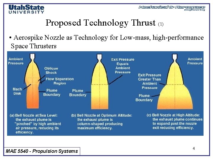
Proposed Technology Thrust (1) • Aerospike Nozzle as Technology for Low-mass, high-performance Space Thrusters MAE 5540 - Propulsion Systems 4
Proposed Technology Thrust (2) • High Expansion ratio for smaller mass/volume • Enhanced Thrust and Specific Impulse • Simple, More reliable operation MAE 5540 - Propulsion Systems 5
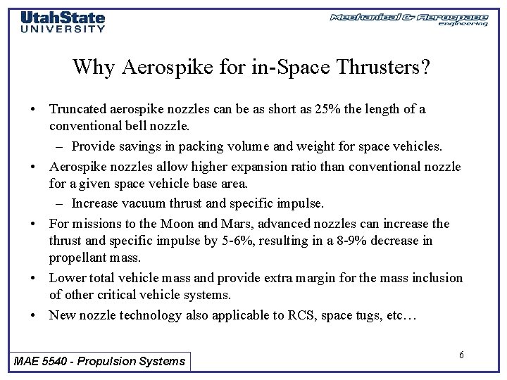
Why Aerospike for in-Space Thrusters? • Truncated aerospike nozzles can be as short as 25% the length of a conventional bell nozzle. – Provide savings in packing volume and weight for space vehicles. • Aerospike nozzles allow higher expansion ratio than conventional nozzle for a given space vehicle base area. – Increase vacuum thrust and specific impulse. • For missions to the Moon and Mars, advanced nozzles can increase thrust and specific impulse by 5 -6%, resulting in a 8 -9% decrease in propellant mass. • Lower total vehicle mass and provide extra margin for the mass inclusion of other critical vehicle systems. • New nozzle technology also applicable to RCS, space tugs, etc… MAE 5540 - Propulsion Systems 6
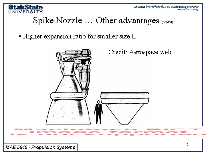
Spike Nozzle … Other advantages (cont’d) • Higher expansion ratio for smaller size II Credit: Aerospace web MAE 5540 - Propulsion Systems 7
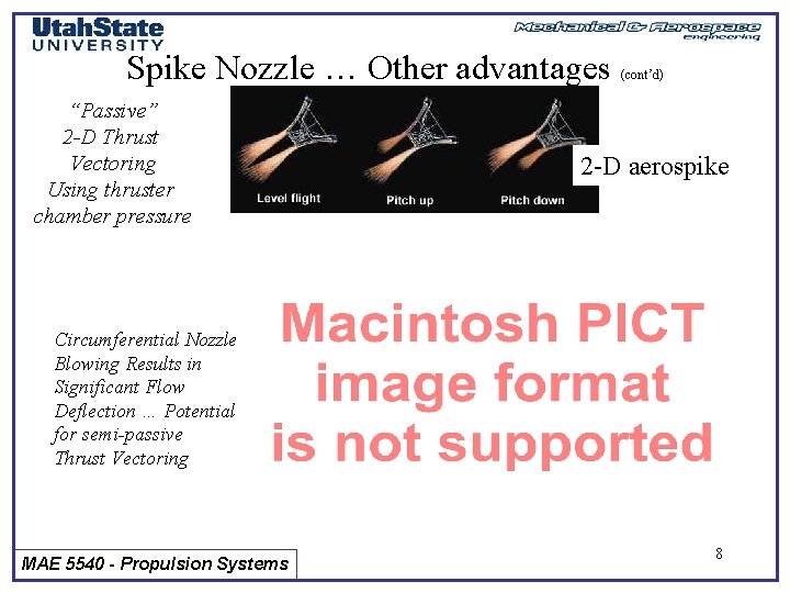
Spike Nozzle … Other advantages “Passive” 2 -D Thrust Vectoring Using thruster chamber pressure (cont’d) 2 -D aerospike Circumferential Nozzle Blowing Results in Significant Flow Deflection … Potential for semi-passive Thrust Vectoring MAE 5540 - Propulsion Systems 8
Spike Nozzle … Disadvantages ) • Only 1 ……. . • Low TRL Level: No aerospike engine has ever flown on an Operational rocket application. As a result, little flight design experience has been gained. High Fidelity, comprehensive ground test data also limited. Almost no correlation of experimental and analytical results Fidelity and controllability data is non existent Current TRL Level 2 -3 tops! MAE 5540 - Propulsion Systems 9
ALTAIR Configuration (Firestar Engineering Concept) Firestar Engineering Proprietary MAE 5540 - Propulsion Systems 10
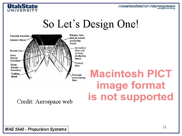
So Let’s Design One! Credit: Aerospace web MAE 5540 - Propulsion Systems 11
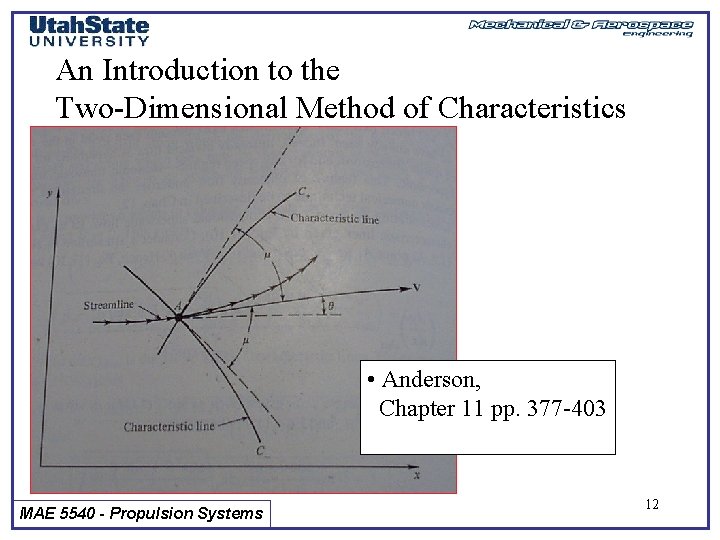
An Introduction to the Two-Dimensional Method of Characteristics • Anderson, Chapter 11 pp. 377 -403 MAE 5540 - Propulsion Systems 12
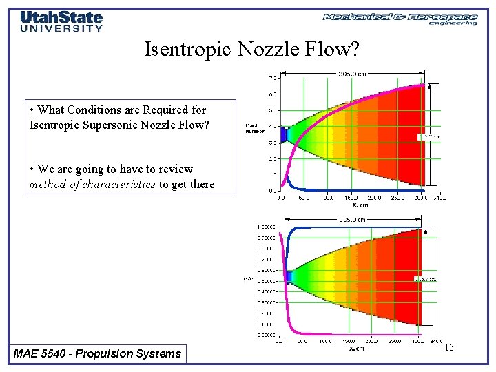
Isentropic Nozzle Flow? • What Conditions are Required for Isentropic Supersonic Nozzle Flow? • We are going to have to review method of characteristics to get there MAE 5540 - Propulsion Systems 13
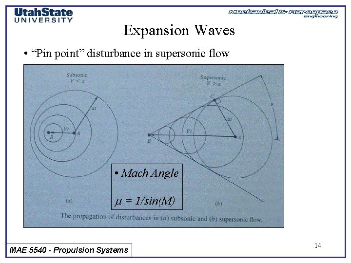
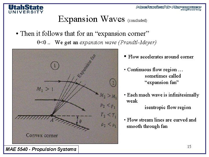
Expansion Waves • “Pin point” disturbance in supersonic flow • Mach Angle m = 1/sin(M) MAE 5540 - Propulsion Systems 14
Expansion Waves (concluded) • Then it follows that for an “expansion corner” q<0. . We get an expansion wave (Prandtl-Meyer) • Flow accelerates around corner • Continuous flow region … sometimes called “expansion fan” • Each mach wave is infinitesimally weak isentropic flow region • Flow stream lines are curved and smooth through fan MAE 5540 - Propulsion Systems 15
Prandtl-Meyer Expansion Fan: Mathematical Analysis Revisited • Consider flow expansion around an infinitesimal corner • From Law of Sines MAE 5540 - Propulsion Systems 16
Prandtl-Meyer Expansion Fan: Mathematical Analysis (cont’d) • Expanding sin(p+m), sin(p m dq), and collecting terms • Letting dq is considered be infinitesimal MAE 5540 - Propulsion Systems 17
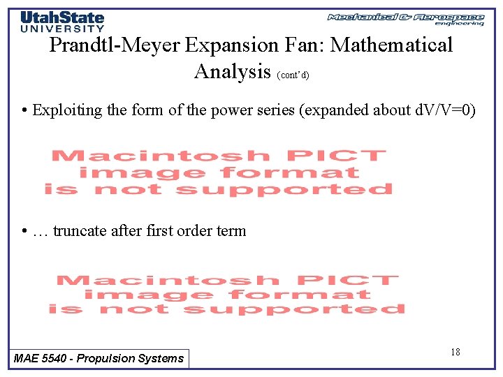
Prandtl-Meyer Expansion Fan: Mathematical Analysis (cont’d) • Exploiting the form of the power series (expanded about d. V/V=0) • … truncate after first order term MAE 5540 - Propulsion Systems 18
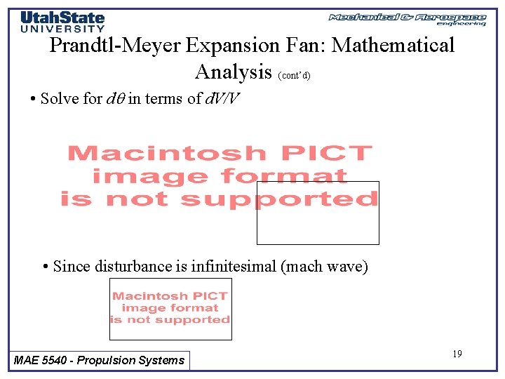
Prandtl-Meyer Expansion Fan: Mathematical Analysis (cont’d) • Solve for dq in terms of d. V/V • Since disturbance is infinitesimal (mach wave) MAE 5540 - Propulsion Systems 19
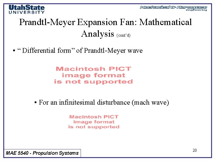
Prandtl-Meyer Expansion Fan: Mathematical Analysis (cont’d) • “ Differential form” of Prandtl-Meyer wave • For an infinitesimal disturbance (mach wave) MAE 5540 - Propulsion Systems 20
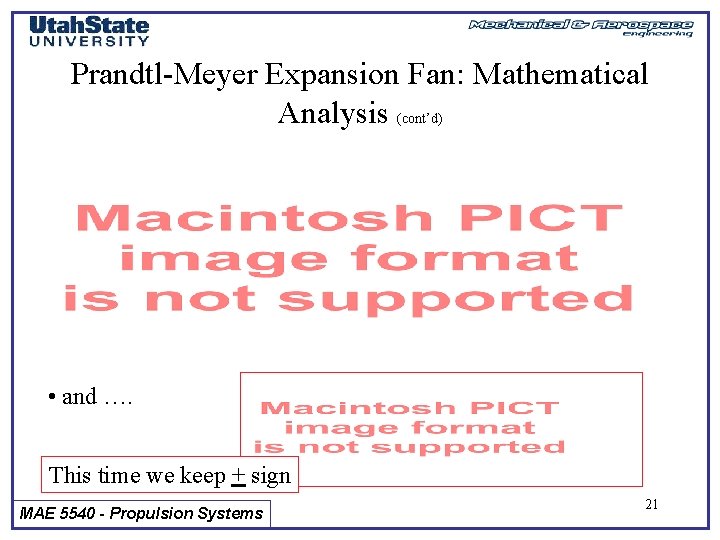
Prandtl-Meyer Expansion Fan: Mathematical Analysis (cont’d) • and …. This time we keep + sign MAE 5540 - Propulsion Systems 21
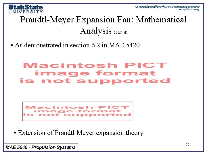
Prandtl-Meyer Expansion Fan: Mathematical Analysis (cont’d) • As demonstrated in section 6. 2 in MAE 5420 • Extension of Prandtl Meyer expansion theory MAE 5540 - Propulsion Systems 22
Method of Characteristics Revisited • Left and Right running characteristic lines Slope: q m • C- “right running” characteristic Line is a Generalization For infinitesimal expansion corner flow MAE 5540 - Propulsion Systems 23
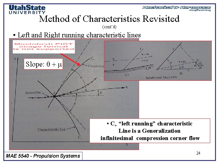
Method of Characteristics Revisited (cont’d) • Left and Right running characteristic lines Slope: q + m • C+ “left running” characteristic Line is a Generalization infinitesimal compression corner flow MAE 5540 - Propulsion Systems 24
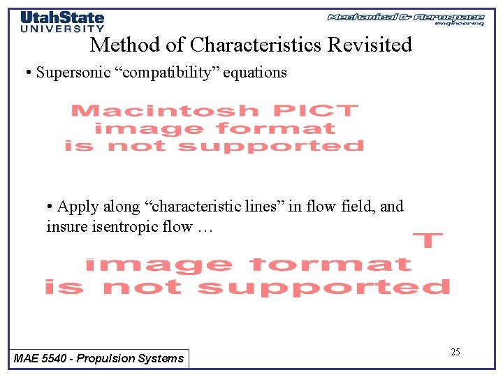
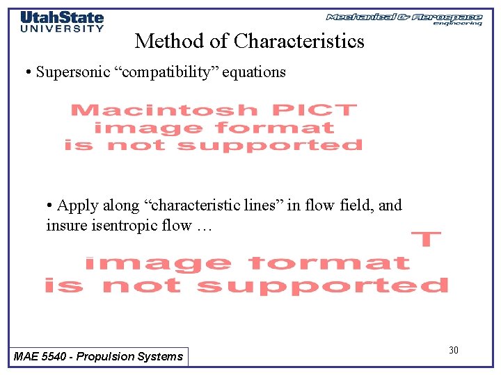
Method of Characteristics Revisited • Supersonic “compatibility” equations • Apply along “characteristic lines” in flow field, and insure isentropic flow … MAE 5540 - Propulsion Systems 25
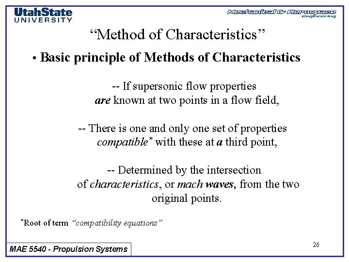
“Method of Characteristics” • Basic principle of Methods of Characteristics -- If supersonic flow properties are known at two points in a flow field, -- There is one and only one set of properties compatible* with these at a third point, -- Determined by the intersection of characteristics, or mach waves, from the two original points. *Root of term “compatibility equations” MAE 5540 - Propulsion Systems 26
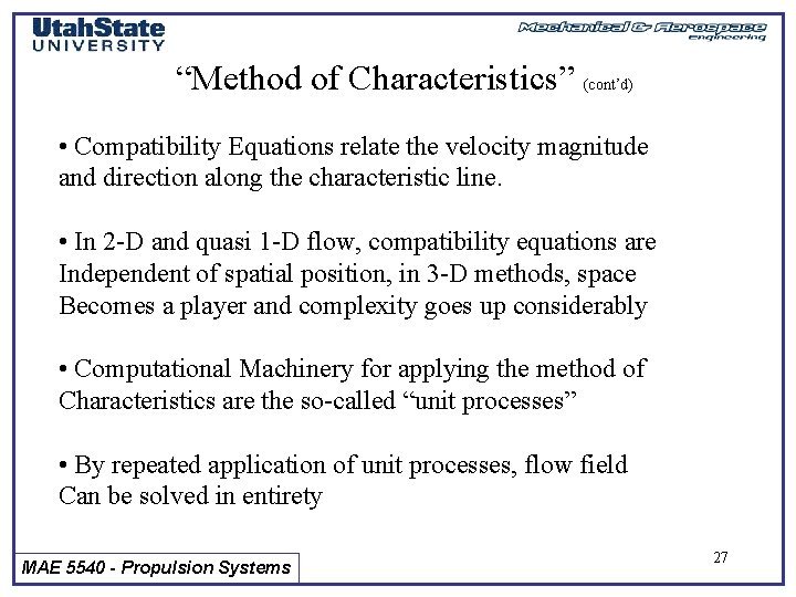
“Method of Characteristics” (cont’d) • Compatibility Equations relate the velocity magnitude and direction along the characteristic line. • In 2 -D and quasi 1 -D flow, compatibility equations are Independent of spatial position, in 3 -D methods, space Becomes a player and complexity goes up considerably • Computational Machinery for applying the method of Characteristics are the so-called “unit processes” • By repeated application of unit processes, flow field Can be solved in entirety MAE 5540 - Propulsion Systems 27
Supersonic Nozzle Design • Strategic contouring will “absorb” mach waves to give isentropic flow in divergent section MAE 5540 - Propulsion Systems 28
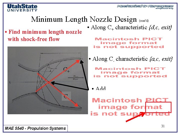
Supersonic Nozzle Design (cont’d) • Rocket Nozzle (Minimum Length) • Wind tunnel diffuser (gradual expansion) • Find minimum length nozzle with shock-free flow MAE 5540 - Propulsion Systems 29
Method of Characteristics • Supersonic “compatibility” equations • Apply along “characteristic lines” in flow field, and insure isentropic flow … MAE 5540 - Propulsion Systems 30
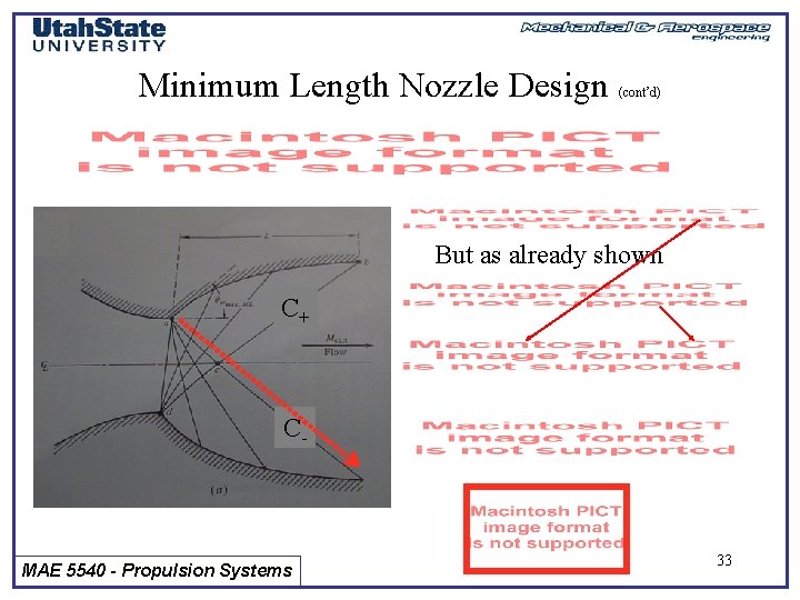
Minimum Length Nozzle Design • Find minimum length nozzle with shock-free flow (cont’d) • Along C+ characteristic {d, c, exit} • Along C- characteristic {a, c, exit} C+ • Add C- MAE 5540 - Propulsion Systems 31
Minimum Length Nozzle Design (cont’d) • Find minimum length nozzle • Along C characteristic {a, c} with shock-free flow at point a C+ • But from Prandtl-Meyer expansion at point a 0 C- MAE 5540 - Propulsion Systems 32
Minimum Length Nozzle Design (cont’d) But as already shown C+ C- MAE 5540 - Propulsion Systems 33
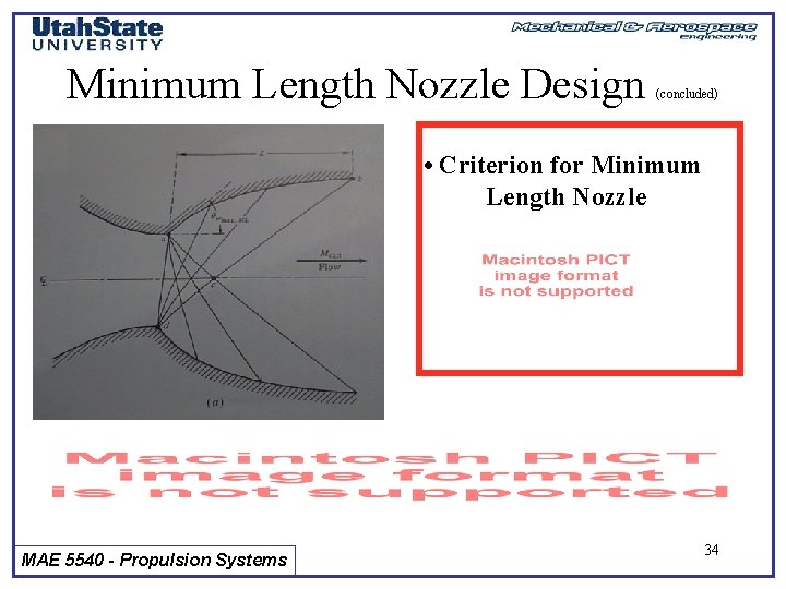
Minimum Length Nozzle Design (concluded) • Criterion for Minimum Length Nozzle MAE 5540 - Propulsion Systems 34
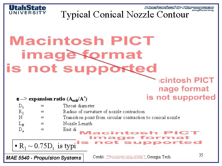
Typical Conical Nozzle Contour e --> expansion ratio (Aexit/A*) Dt R 1 N LN De = = = Throat diameter Radius of curvature of nozzle contraction Transition point from circular contraction to conical nozzle Nozzle Length Exit diameter • R 1 ~ 0. 75 Dt is typical MAE 5540 - Propulsion Systems Credit: Georgia Tech 35
Typical Conical Nozzle Contour (Cont’d) • Solve for Nozzle length in terms of other parameters MAE 5540 - Propulsion Systems 36
Typical Conical Nozzle Contour • Using trig identities • R 5540 typical MAE Propulsion 1 ~ -0. 75 D t is Systems (Cont’d) 37
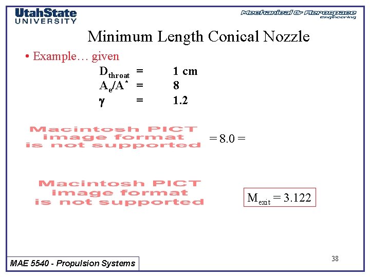
Minimum Length Conical Nozzle • Example… given Dthroat = Ae/A* = = 1 cm 8 1. 2 = 8. 0 = Mexit = 3. 122 MAE 5540 - Propulsion Systems 38
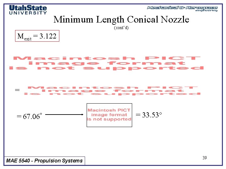
Minimum Length Conical Nozzle (cont’d) Mexit = 3. 122 = = 67. 06 MAE 5540 - Propulsion Systems = 33. 53 39
Minimum Length Conical Nozzle (cont’d) • R 1 ~ 0. 75 Dt is typical …. R 1=0. 75 cm = 33. 53 • Any shorter and you have “problems” = = 1. 606 cm MAE 5540 - Propulsion Systems 40
What happens when a nozzle expands too quickly? • i. e. …. A mess … for a given Operating condition there is only so fast we can expand a Conventional Nozzle • Is there an alternative to the minimum length nozzle? MAE 5540 - Propulsion Systems 41
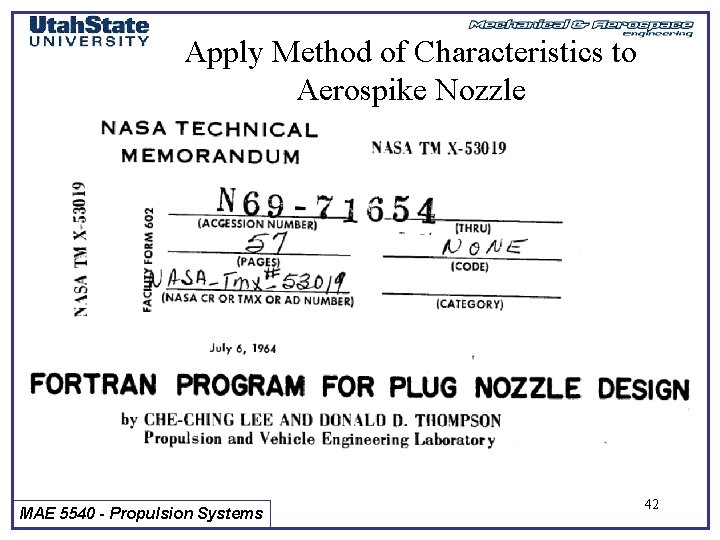
Apply Method of Characteristics to Aerospike Nozzle MAE 5540 - Propulsion Systems 42
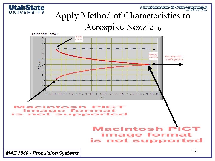
Apply Method of Characteristics to Aerospike Nozzle (1) MAE 5540 - Propulsion Systems 43
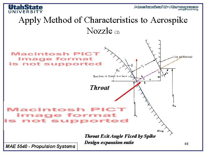
Apply Method of Characteristics to Aerospike Nozzle (2) Throat MAE 5540 - Propulsion Systems Throat Exit Angle Fixed by Spike Design expansion ratio 44
Apply Method of Characteristics to Aerospike Nozzle (3) Along spike surface MAE 5540 - Propulsion Systems 45
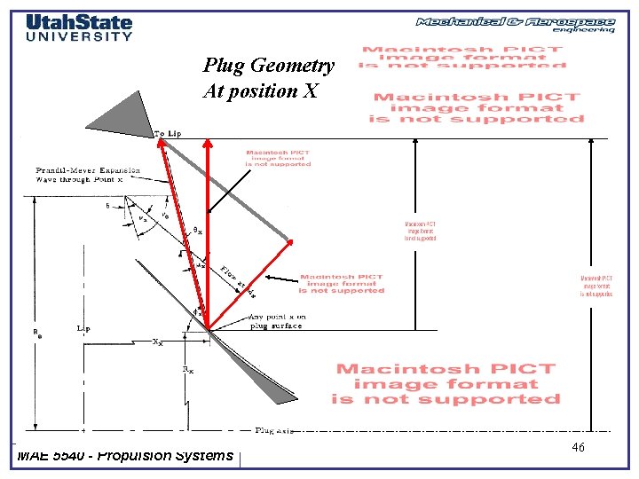
Plug Geometry At position X MAE 5540 - Propulsion Systems 46
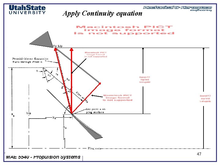
Apply Continuity equation MAE 5540 - Propulsion Systems 47
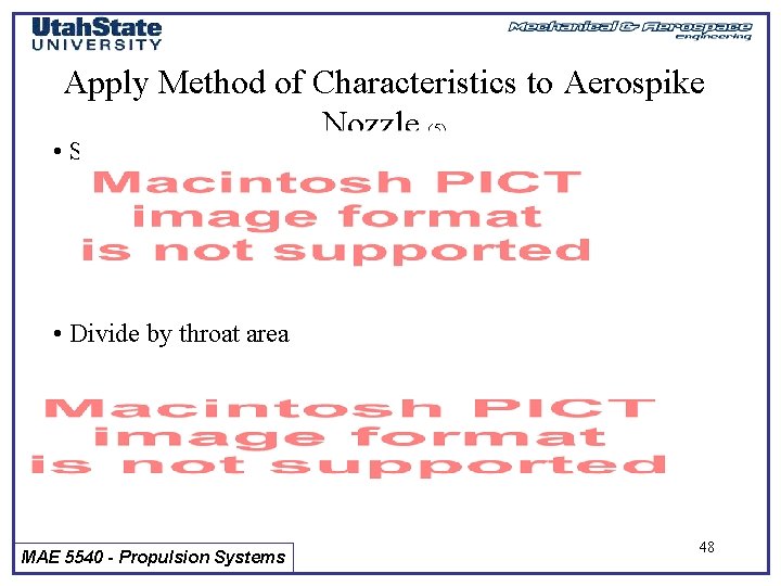
Apply Method of Characteristics to Aerospike Nozzle (5) • Solving for Ax • Divide by throat area MAE 5540 - Propulsion Systems 48
Apply Method of Characteristics to Aerospike Nozzle (6) • Simplifying MAE 5540 - Propulsion Systems 49
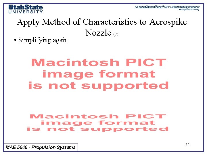
Apply Method of Characteristics to Aerospike Nozzle (7) • Simplifying again MAE 5540 - Propulsion Systems 50
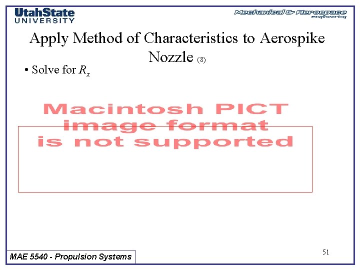
Apply Method of Characteristics to Aerospike Nozzle (8) • Solve for Rx MAE 5540 - Propulsion Systems 51
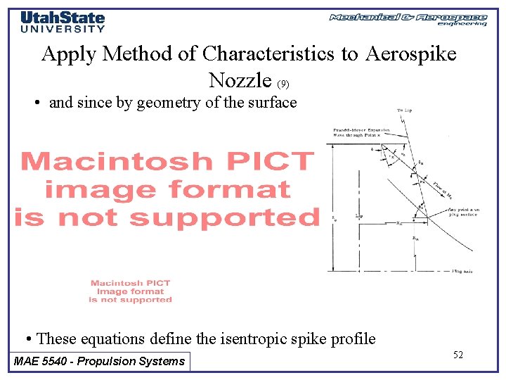
Apply Method of Characteristics to Aerospike Nozzle (9) • and since by geometry of the surface • These equations define the isentropic spike profile MAE 5540 - Propulsion Systems 52
Apply Method of Characteristics to Aerospike Nozzle (10) Exit pressure expands to ambient condition MAE 5540 - Propulsion Systems 53
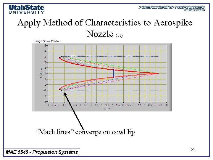
Apply Method of Characteristics to Aerospike Nozzle (11) “Mach lines” converge on cowl lip MAE 5540 - Propulsion Systems 54
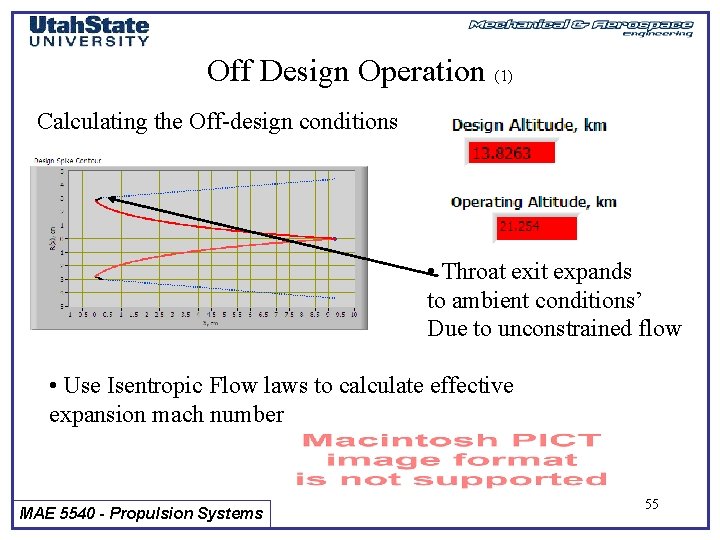
Off Design Operation (1) Calculating the Off-design conditions • Throat exit expands to ambient conditions’ Due to unconstrained flow • Use Isentropic Flow laws to calculate effective expansion mach number MAE 5540 - Propulsion Systems 55
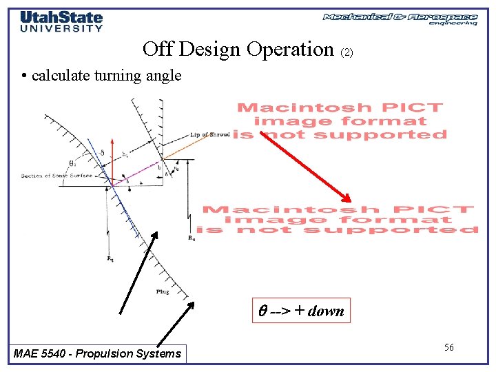
Off Design Operation (2) • calculate turning angle --> + down MAE 5540 - Propulsion Systems 56
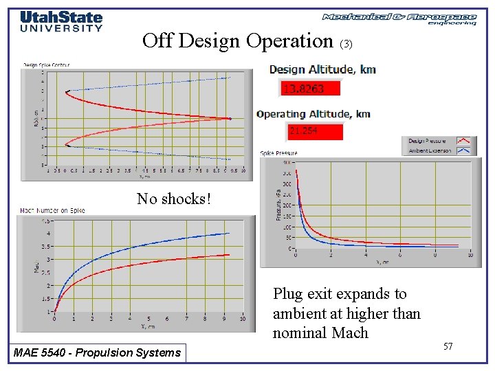
Off Design Operation (3) No shocks! Plug exit expands to ambient at higher than nominal Mach MAE 5540 - Propulsion Systems 57
Off Design Operation (4) No shocks! MAE 5540 - Propulsion Systems Plug exit compresses to ambient at smaller than 58 nominal Mach
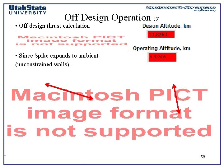
Off Design Operation (5) • Off design thrust calculation • Since Spike expands to ambient (unconstrained walls). . MAE 5540 - Propulsion Systems 59
Compare Aerospike to Minimum Expansion Ratio Nozzle 6. 6 cm length 8. 03 cm length MAE 5540 - Propulsion Systems 60
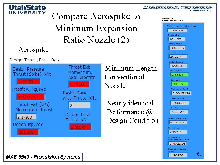
Compare Aerospike to Minimum Expansion Ratio Nozzle (2) Aerospike Minimum Length Conventional Nozzle Nearly identical Performance @ Design Condition MAE 5540 - Propulsion Systems 61
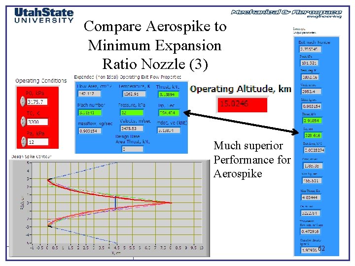
Compare Aerospike to Minimum Expansion Ratio Nozzle (3) Much superior Performance for Aerospike MAE 5540 - Propulsion Systems 62
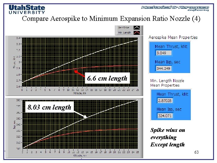
Compare Aerospike to Minimum Expansion Ratio Nozzle (4) 6. 6 cm length 8. 03 cm length Spike wins on everything Except length MAE 5540 - Propulsion Systems 63
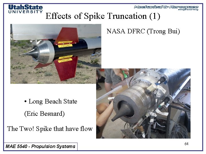
Effects of Spike Truncation (1) NASA DFRC (Trong Bui) • Long Beach State (Eric Besnard) The Two! Spike that have flow MAE 5540 - Propulsion Systems 64
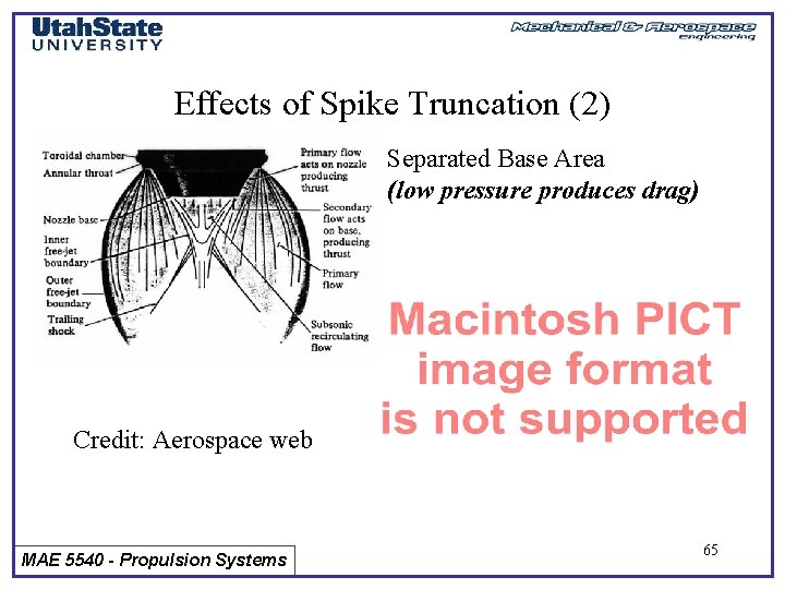
Effects of Spike Truncation (2) Separated Base Area (low pressure produces drag) Credit: Aerospace web MAE 5540 - Propulsion Systems 65
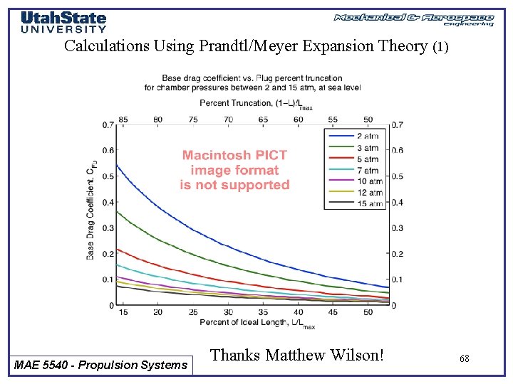
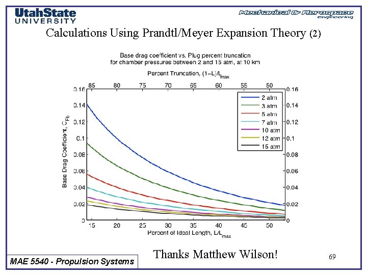
Effects of Spike Truncation (4) • Primary Loss is base drag MAE 5540 - Propulsion Systems 66
Effects of Spike Truncation (3) Effects are not as dramatic as one would think! … At higher altitudes truncation hurts you less MAE 5540 - Propulsion Systems 67
Calculations Using Prandtl/Meyer Expansion Theory (1) MAE 5540 - Propulsion Systems Thanks Matthew Wilson! 68
Calculations Using Prandtl/Meyer Expansion Theory (2) MAE 5540 - Propulsion Systems Thanks Matthew Wilson! 69
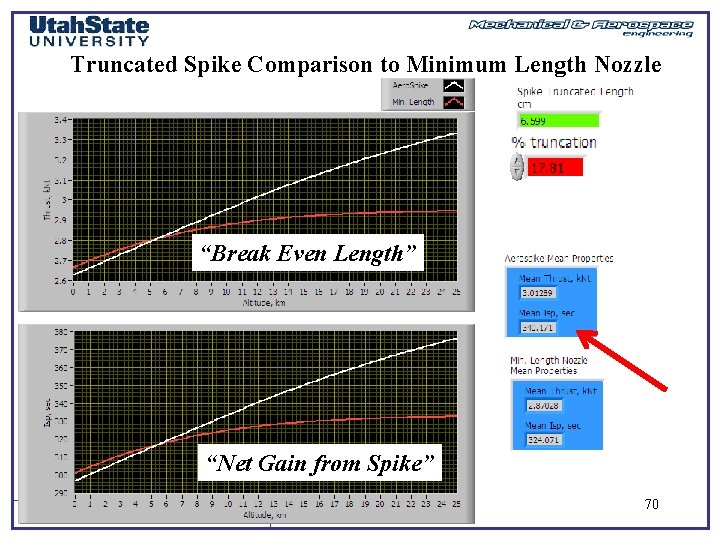
Truncated Spike Comparison to Minimum Length Nozzle “Break Even Length” “Net Gain from Spike” MAE 5540 - Propulsion Systems 70
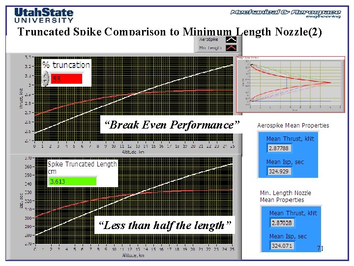
Truncated Spike Comparison to Minimum Length Nozzle(2) “Break Even Performance” “Less than half the length” MAE 5540 - Propulsion Systems 71
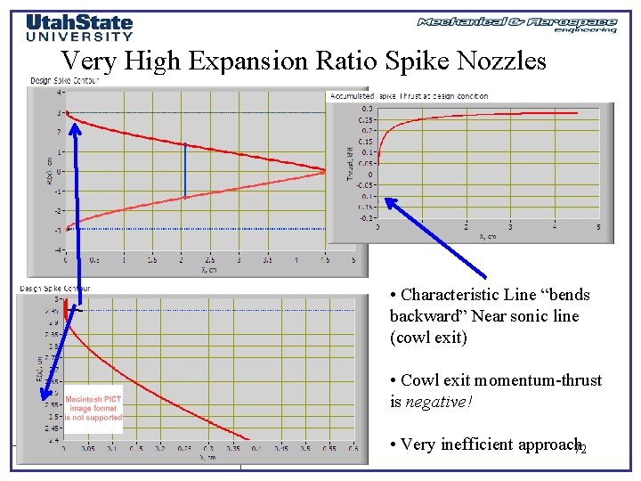
Very High Expansion Ratio Spike Nozzles • Characteristic Line “bends backward” Near sonic line (cowl exit) • Cowl exit momentum-thrust is negative! MAE 5540 - Propulsion Systems • Very inefficient approach 72
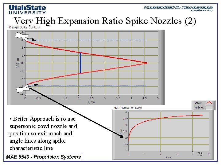
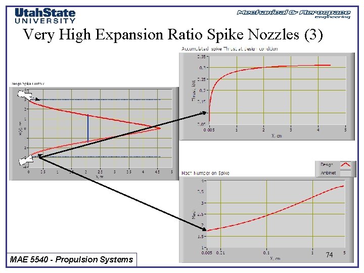
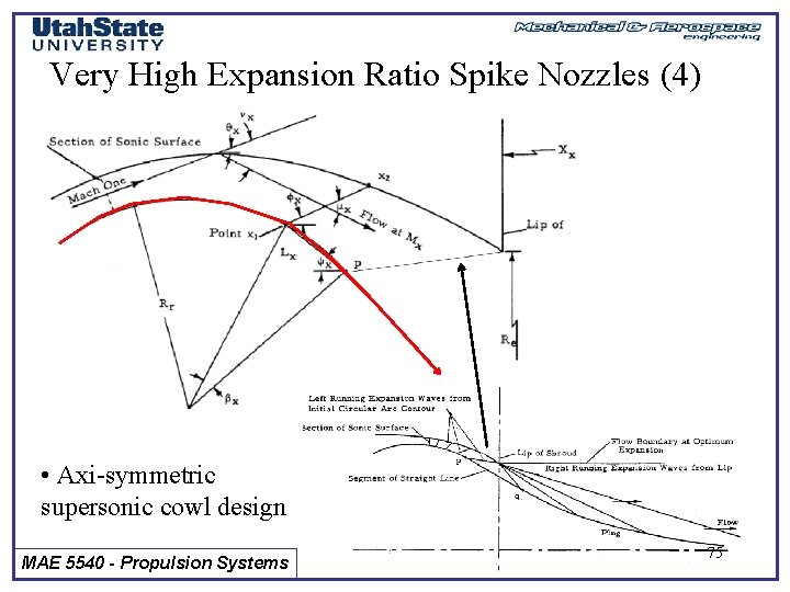
Very High Expansion Ratio Spike Nozzles (2) • Better Approach is to use supersonic cowl nozzle and position so exit mach and angle lines along spike characteristic line MAE 5540 - Propulsion Systems 73
Very High Expansion Ratio Spike Nozzles (3) MAE 5540 - Propulsion Systems 74
Very High Expansion Ratio Spike Nozzles (4) • Axi-symmetric supersonic cowl design MAE 5540 - Propulsion Systems 75
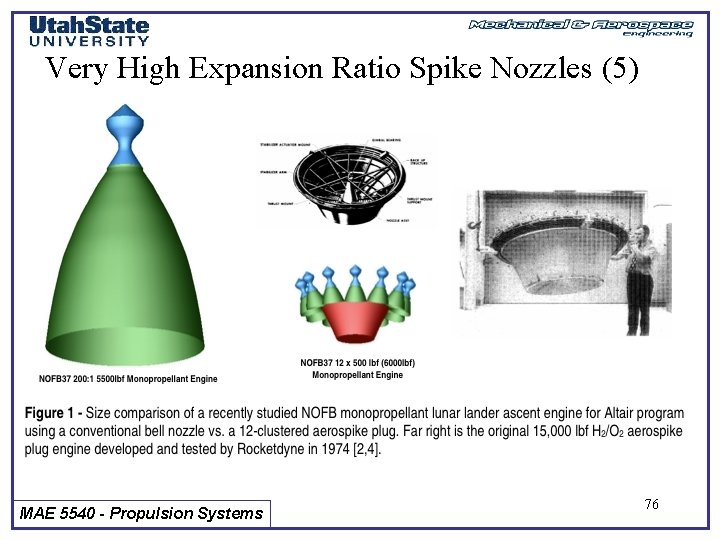
Very High Expansion Ratio Spike Nozzles (5) MAE 5540 - Propulsion Systems 76