Metal Joining Process Prepared by Darshan K Bhatt

Metal Joining Process Prepared by, Darshan K Bhatt

A Brief History of Welding • Late 19 th Century • Scientists/engineers apply advances in electricity to heat and/or join metals (Le Chatelier, Joule, etc. ) • Early 20 th Century • Prior to WWI welding was not trusted as a method to join two metals due to crack issues • 1930’s and 40’s • Industrial welding gains acceptance and is used extensively in the war effort to build tanks, aircraft, ships, etc. • Modern Welding • the nuclear/space age helps bring welding from an art to a science

Types of Welding Fusion Welding Homogeneous Gas Welding Electroslag High Energy Beam Electric Arc Pressure Welding Heterogeneous Brazing Friction Welding Soldering MIG TIG Shielded Metal Arc – “Stick”

Classification of welding process

Welding Processes v Fusion Welding Involves melting and solidification v Solid phase welding Explosive welding Diffusion welding Friction welding

Fusion welding • Most commonly used process • Heat source: electric arc, gas flame, laser • Filler metal From electrode, rod, wire, powder, flux Independently added filler No filler (Autogenous welding)

Weld • The AWS definition for welding process is “ A materials joining process which produce coalescence of materials by heating them to suitable temperature with or without he application of pressure or by the application of pressure alone and with or without use of filler metal”. • Filler (if used) has a melting temperature similar to the parts being joint.

Weldability • The capacity of material to be welded under the imposed fabrication condition into a specific, suitably designed structure and to perform satisfactorily in intended service.

Weldability of a Metal • Metallurgical Capacity • Parent metal will join with the weld metal without formation of deleterious constituents or alloys • Mechanical Soundness • Joint will be free from discontinuities, gas porosity, shrinkage, slag, or cracks • Serviceability • Weld is able to perform under varying conditions or service (e. g. , extreme temperatures, corrosive environments, fatigue, high pressures, etc. )

Factor affecting weldability • • • Design Physical properties Solidification of weld metal Dilution Chemical properties Contaminant gases Gas metal reaction Metallurgical properties Service environment

Fusion Welding Principles • Base metal is melted • Filler metal may be added • Heat is supplied by various means • • Oxyacetylene gas Electric Arc Plasma Arc Laser

Fusion Welding principle ELECTRODE COATING CORE WIRE WELDING ATMOSPHERE ARC STREAM ARC POOL SOLIDIFIED SLAG PENETRATION DEPTH WELD BASE METAL

Fusion weld structure

Thermal HAZ region

HAZ structure

Weld Metal Protection • During fusion welding, the molten metal in the weld “puddle” is susceptible to oxidation • Must protect weld puddle (arc pool) from the atmosphere • Methods • Weld Fluxes • Inert Gases • Vacuum

Weld Fluxes • Typical fluxes • Si. O 2, Ti. O 2, Fe. O, Mg. O, Al 2 O 3 • Produces a gaseous shield to prevent contamination • Act as scavengers to reduce oxides • Add alloying elements to the weld • Influence shape of weld bead during solidification

Inert Gases • Argon, helium, nitrogen, and carbon dioxide • Form a protective envelope around the weld area • Used in • MIG • TIG • Shield Metal Arc

Vacuum • Produce high-quality welds • Used in electron beam welding • Nuclear/special metal applications • Zr, Hf, Ti • Reduces impurities by a factor of 20 versus other methods • Expensive and time-consuming
 • Shielded Metal")
Types of Fusion Welding • Oxyacetylene Cutting/Welding (Gas cutting / welding) • Shielded Metal Arc (“SMAW”) • Metal Inert Gas (MIG) • Tungsten Inert Gas (TIG)

Gas Welding • Sound weld is obtained by selecting proper size of flame, filler material and method of moving torch • The temperature generated during the process is 33000 c • When the metal is fused, oxygen from the atmosphere and the torch combines with molten metal and forms oxides, results defective weld • Fluxes are added to the welded metal to remove oxides • Common fluxes used are made of sodium, potassium. Lithium and borax. • Flux can be applied as paste, powder, liquid, solid coating or gas.

GAS WELDING EQUIPMENT. . .

GAS WELDING EQUIPMENT. . . 1. Gas Cylinders Pressure Oxygen – 125 kg/cm 2 Acetylene – 16 kg/cm 2 2. Regulators Working pressure of oxygen 1 kg/cm 2 Working pressure of acetylene 0. 15 kg/cm 2 Working pressure varies depends upon the thickness of the work pieces welded. 3. Pressure Gauges 4. Hoses 5. Welding torch 6. Check valve 7. Non return valve

Gas Cylinders • Two large steel cylinders, capable to withstand high pressure are needed to keep oxygen and acetylene separately. • Cylinders are painted with different colors : oxygen cylinder in black color and acetylene cylinder in maroon or red color. • Oxygen is filled at pressure to 2000 pound per square inch (PSI). • Large weight of acetylene is kept dissolved in acetone. • Acetylene cylinder should not be exposed to higher temperature for safety reasons.

Welding Torch

Welding Rods • These are also called filler metals. Filler metal is typically in the form of rod, 90 mm long and diameter ranging from 1. 6 mm to 9. 5 mm. • Composition of filler metal must be same as that of base metal. Two types of welding rods are generally available. • One is coated welding rods, which have coating of flux. • Others are bare welding rods having no coating of flux. • Different types of welding rods are used for welding of different metals. Some examples are given below.
 Welding • Flame formed by burning a mix of acetylene (C 2")
Gas (Oxyacetylene) Welding • Flame formed by burning a mix of acetylene (C 2 H 2) and oxygen TORCH TIP Inner Cone: 5000 -6300 deg F 2300 deg F Combustion Envelope 3800 deg F • Fusion of metal is achieved by passing the inner cone of the flame over the metal • Oxyacetylene can also be used for cutting metals

Flames • The flame can be divided in to three zones. Zone ‘ 1’ is very near to the outlet of torch, where oxygen reacts with acetylene and burning of two gases takes place. • Zone ‘ 2’ produces carbon monoxide and hydrogen in ratio 2 : 1 by volume. • This zone gives the highest temperature of Welding the flame • Zone ‘ 3’ is the outermost zone of the flame. • Temperature of this zone is comparatively low. • This zone converts CO to CO 2 and H 2 O vapours.

Types of Flames • Oxygen is turned on, flame immediately changes into a long white inner area (Feather) surrounded by a transparent blue envelope is called Carburizing flame (30000 c) • Addition of little more oxygen give a bright whitish cone surrounded by the transparent blue envelope is called Neutral flame (It has a balance of fuel gas and oxygen) (32000 c) • Used for welding steels, aluminium, copper and cast iron • If more oxygen is added, the cone becomes darker and more pointed, while the envelope becomes shorter and more fierce is called Oxidizing flame Has the highest temperature about 34000 c • Used for welding brass and brazing operation

Types of Flames

GAS CUTTING • Ferrous metal is heated in to red hot condition and a jet of pure oxygen is projected onto the surface, which rapidly oxidizes • Oxides having lower melting point than the metal, melt and are blown away by the force of the jet, to make a cut • Fast and efficient method of cutting steel to a high degree of accuracy • Torch is different from welding • Cutting torch has preheat orifice and one central orifice for oxygen jet • PIERCING and GOUGING are two important operations • Piercing, used to cut a hole at the centre of the plate or away from the edge of the plate • Gouging, to cut a groove into the steel surface

Arc welding • Electric arc welding is one of the fusion welding processes in which coalescence of the metal is achieved by the heat from an electric arc between an electrode and work piece. • Electric arc is generated when electrode is brought into contact with the work and is then quickly separated by a short distance approximately 2 mm. • The circuit operates at low voltage and high current so arc is established in the gap due to thermoionic emission from electrode (Cathode) to work piece (Anode). • This arc produces at temperature of the order of 5500°C or higher.

Arc welding
 • An electric arc is generated between a coated electrode")
Shielded Metal Arc (Stick) • An electric arc is generated between a coated electrode and the parent metal • The coated electrode carries the electric current to form the arc, produces a gas to control the atmosphere and provides filler metal for the weld bead • Electric current may be AC or DC. If the current is DC, the polarity will affect the weld size and application

Metal arc welding
 Power source (welding machine) • (b)")
Arc Welding Equipments Facilitator Equipment Welding • (a) Power source (welding machine) • (b) Electrode holder • (c) Work table • (d) Cables (for connection) • (e) Finishing devices like chipping, hammer, wire brush, etc. Consumable Equipment • (a) Electrode • (b) Flux • (c) Workpiece • (d) Filler metal Protecting Equipment • (a) Welding shields • (b) Goggles • (c) Screens • (d) Gloves • (e) Apron
")
Welding Power Sources • Shielded metal arc welding may utilize either alternating current (AC) or direct current (DC). • Whether to use an AC, DC, or AC/DC power source depends on the type of welding to be done and the electrodes used.

Factors affecting power source 1. Electrode Selection - Using a DC power source allows the use of a greater range of electrode types. While most of the electrodes are designed to be used on AC or DC, some will work properly on DC. 2. Metal Thickness - DC power sources may be used for welding both heavy sections and light gauge work. Sheet metal is more easily welded with DC because it is easier to strike and maintain the DC arc at low currents. 5. Arc Blow - When welding with DC, magnetic fields are set up throughout the weldment. In weldments that have varying thickness and protrusions, this magnetic field can affect the arc by making it stray or fluctuate in direction. This condition is especially troublesome when welding in corners. AC seldom causes this problem because of the rapidly reversing magnetic field produced.

Factors affecting power source • 3. Distance from Work - If the distance from the work to the power source is great, AC is the best choice since the voltage drop through the cables is lower than with DC. Even though welding cables are made of copper or aluminum (both good conductors), the resistance in the cables becomes greater as the cable length increases. In other words, a voltage reading taken between the electrode and the work will be somewhat lower than a reading taken at the output terminals of the power source. This is known as voltage drop.
 produces welds with shallow penetration; however,")
Factors affecting power source • Electrode negative (-) produces welds with shallow penetration; however, the electrode melt-off rate is high. • Electrode positive (+)produces welds with deep penetration and a narrower weld bead.

Electrode • The electrode rod is made of a material that is compatible with the base material being welded and is covered with a flux that gives off vapors that serve as a shielding gas and provide a layer of slag, both of which protect the weld area from atmospheric contamination.
 AWS")
Electrode Designation • To designate the electrode two basic standards are used, 1) AWS standard: Rods are commonly known by their AWS (American Welding Society) name, so it's a useful standard to decode. We'll use E 7018 rods as an example: 2) ISO standard: The European coding system has recently been amended and is now an International Standard ISO 2560 which is basically the same as EN 499.

AWS standard • E 7018: E Electrode: E just means the electrode is for MMA welding and has a flux coating. 70 Tensile Strength (in ksi): The minimum tensile strength measured in kilo-pounds(force) per square inch. In our example 70 ksi would be 70, 000 psi pounds(force) per square inch, or 480 N/mm 2. 1 Welding Positions: 1. All position 2. Flat and horizontal position 8 Flux Coating and Current: 0 - High cellulose sodium (Cellulosic)- DC+ 1 - High cellulose potassium - AC or DC+ or DC 2 - High titania sodium (Rutile) - AC or DC 3 - High titania potassium (Rutile) - AC or DC+ 4 - Iron powder titania (Rutile) - AC or DC- or DC+ -------8 - Iron powder low hydrogen (Basic) - AC or DC+

ISO standard • In the ISO standard E 7018 rods are known as E 46 4 B 32 H 5. E Electrode E just means the electrode is for MMA welding and has a flux coating. 46 Yield Strength (in N/mm 2) Multiply this number by 10 for the minimum yield strength in N/mm 2. In our example 46 will represent a minimum yield strength of 460 N/mm 2 This is not directly equivalent to the tensile strength in the AWS standard. Yield Strength is where the metal starts to deform plastically (when it doesn't spring back to it's original form after the load is released). Tensile Strength is when the metal breaks.

ISO standard • 4 - Minimum Impact Temperature at 46 J This represents the temperature at which the weld material becomes brittle.

ISO standard • 3 - Current Type and Recovery 'Recovery' is the weight of weld metal deposited in the weld relative to the weight of the core wire. Over 100% means that the weld will weigh more than the weight of the core wire. In other words the coating contains iron powder (or in some rods other alloys). 2 - Welding Positions H - Hydrogen content

• B - Rod Flux Coating • • AAcid A type of rutile characterised by very smooth arc but with minimal penetration and prone to moisture pick up. good on very thin sheet. CCellulosic (E 6010) An organic coating containing Cellulose with good penetration, high deposition, and easily removed slag, but high hydrogen content • • • . BBasic (E 7018 or E 7016) These chemically basic (alkali) coatings contain calcium carbonate or calcium fluoride. They are normally used for Low Hydrogen rods. RRutile (E 6013) In welding rod coatings it provides slag cover, arc stability (it ionizes easily) and helps the fast freeze ability of positional rods. RCRutile Cellulosic (E 6013) Most rutiles contain some cellulose to improve the penetration, otherwise the same as R.

Inert Gas Welding • For materials such as Al or Ti which quickly form oxide layers, a method to place an inert atmosphere around the weld puddle had to be developed
 • Uses a consumable electrode (filler wire made of the")
Metal Inert Gas (MIG) • Uses a consumable electrode (filler wire made of the base metal) • Inert gas is typically Argon CONSUMABLE ELECTRODE DRIVE WHEELS POWER SOURCE SHIELDING GAS BASE METAL ARC COLUMN PUDDLE
 • Tungsten electrode acts as a cathode • A plasma")
Tungsten Inert Gas (MIG) • Tungsten electrode acts as a cathode • A plasma is produced between the tungsten cathode and the base metal which heats the base metal to its melting point • Filler metal can be added to the weld pool TUNGSTEN ELECTRODE POWER SOURCE TUNGSTEN ELECTRODE (CATHODE) ++ SHIELDING GAS BASE METAL ARC COLUMN PUDDLE ++ - - BASE METAL (ANODE)
 refers to a group of welding")
Resistance Welding process • Electric resistance welding (ERW) refers to a group of welding processes that produce coalescence of faying surfaces where heat to form the weld is generated by the electrical resistance of material combined with the time and the force used to hold the materials together during welding. 1. Spot welding 2. Seam welding

Spot Welding • Spot welding is a resistance welding method used to join two or more overlapping metal sheets, studs, projections, electrical wiring hangers, some heat exchanger fins, and some tubing. • Usually power sources and welding equipment are sized to the specific thickness and material being welded together. • The thickness is limited by the output of the welding power source and thus the equipment range due to the current required for each application. • Usually, two copper electrodes are simultaneously used to clamp the metal sheets together and to pass current through the sheets.

Spot Welding

Seam Welding • Resistance seam welding is a process that produces a weld at the faying surfaces of two similar metals. • The seam may be a butt joint or an overlap joint and is usually an automated process. • It differs from butt welding in that butt welding typically welds the entire joint at once and seam welding forms the weld progressively, starting at one end. • Like spot welding, seam welding relies on two electrodes, usually made from copper, to apply pressure and current. • The electrodes are disc shaped and rotate as the material passes between them.

Seam Welding

Projection Welding Process • “Projection welding is an electric resistance welding process that produces welds by the heat obtained from the resistance to the flow of the welding current. The resulting welds are localized at predetermined points by projections, embossments, or intersections”. a. Embossed b. Stud-to-Plate c. Annular

Projection Welding Process

Welding Positions INCREASING DIFFICULTY FLAT HORIZONTAL VERTICAL OVERHEAD

Weld Defects • Undercuts/Overlaps • Grain Growth • A wide T will exist between base metal and HAZ. Preheating and cooling methods will affect the brittleness of the metal in this region • Blowholes • Are cavities caused by gas entrapment during the solidification of the weld puddle. Prevented by proper weld technique (even temperature and speed)

Weld Defects • Inclusions • Impurities or foreign substances which are forced into the weld puddle during the welding process. Has the same effect as a crack. Prevented by proper technique/cleanliness. • Segregation • Condition where some regions of the metal are enriched with an alloy ingredient and others aren’t. Can be prevented by proper heat treatment and cooling. • Porosity • The formation of tiny pinholes generated by atmospheric contamination. Prevented by keeping a protective shield over the molten weld puddle.

Residual Stresses • Rapid heating and cooling results in thermal stresses detrimental to joint strength. • Prevention • Edge Preparation/Alignment – beveled edges and space between components to allow movement • Control of heat input – skip or intermittent weld technique • Preheating – reduces expansion/contraction forces (alloys) and removes moisture from the surface • Peening – help metal stretch as it cools by hitting with a hammer. Use with care since it may work harden the metal • Heat Treatment – “soak” the metal at a high temperature to relieve stresses • Jigs and Fixtures – prevent distortion by holding metal fixed • Number of Passes – the fewer the better.

Joint Design BUTT JOINT FILLET JOINT STRAP JOINT LAP JOINT CORNER JOINT

Generalized Welding Symbol FAR SIDE DETAILS Weld Geometry Electrode Material D L 1 -L 2 ARROW SIDE DETAILS Field weld symbol Weld all-around for pipes, etc. D = Weld Depth (usually equal to plate thickness) L 1 = Weld Length L 2 = Distance between centers for stitched welds The Field Weld Symbol is a guide for installation. Shipyards normally do not use it, except in modular construction.

Example Welding Symbol Geometry symbol for V-groove One-sided welds are max 80% efficient Two sided are 100% efficient 1/2 1/2”
 Backing")
Weld Symbols (Butt Joints) Backing
")
Weld Symbol (Fillet Joints)
")
Weld Symbol (Corner Joints)

Non - Conventional Welding Process
 FW process in which heat for coalescence is produced by superheated")
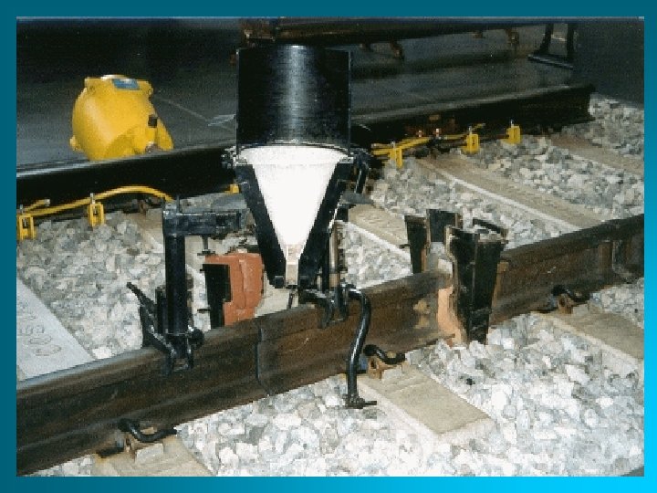
Thermit Welding (TW) FW process in which heat for coalescence is produced by superheated molten metal from the chemical reaction of thermit • Thermit = mixture of Al and Fe 3 O 4 fine powders that produce an exothermic reaction when ignited • Also used for incendiary bombs • Filler metal obtained from liquid metal • Process used for joining, but has more in common with casting than welding
 Thermit welding: (1) Thermit ignited; (2) crucible tapped, superheated metal flows")
Thermit Welding (TW) Thermit welding: (1) Thermit ignited; (2) crucible tapped, superheated metal flows into mold; (3) metal solidifies to produce weld joint.

TW Applications • Joining of railroad rails • Repair of cracks in large steel castings and forgings • Weld surface is often smooth enough that no finishing is required

Laser Welding • • Photons transmit energy and heat • • Energy intensity up to 109 Watts/cm 2 • • Depth to width of hole up to 50 x • • Automatic controllers needed • • 90% efficiency • • Reflectors don’t weld easily

Laser Welding

Electron Beam Welding • Electrons strike surface and generate heat • Best performed in a vacuum • Work piece must be a conductor • Magnetic fields affect beam • Current to 1/2 A • Power to 100 k. W • X-rays produced

Electron Beam Welding
 electron-beam or laser-beam welding •")
Weld Comparison Size of weld beads in • (a) electron-beam or laser-beam welding • (b) conventional arc welding.
: (1) rotating part, no contact; (2) parts brought")
Friction Welding • Friction welding (FRW): (1) rotating part, no contact; (2) parts brought into contact to generate friction heat; (3) rotation stopped and axial pressure applied; and (4) weld created.

Friction Welding

Friction Stir Welding

Explosive Welding
- Slides: 81