METAL FORMING Module5 High Energy Rate Forming Methods


 Production rates are higher, as parts are made at")
 Production cost is low as power hammer (or press) is eliminated in")
 The required final shape/ dimensions are obtained in one stroke (or step),")
 Highly skilled person are required from design to execution. ii) Transient stresses")
 Governmental regulations/ procedures / safety norms must be followed. vi) Dies need")
 In ship building – to form large plates / parts (up to")

 Unconfined type or Stand off technique 2) Confined type")
")


 Shock wave is efficiently transmitted through water and energy is transmitted effectively")


")

 Entire shock wave front is utilized as there is no loss in")


 Better control of the pressure pulse as source of energy is electrical-")
 Suitable only for smaller works ii) Need for vacuum makes the equipment")


 Suitable for small tubes ii) Operations like collapsing, bending and crimping can")
 Applicable only for electrically conducting materials. ii) Not suitable for large work")


 is rotated rapidly")

 are crushed in a")


- Slides: 67
METAL FORMING Module-5 High Energy Rate Forming Methods & Powder Metallurgy
Syllabus • High Energy Rate Forming Methods & Powder Metallurgy: High Energy Rate Forming Methods: Principles, advantages and applications, explosive forming, electro hydraulic forming, Electromagnetic forming. • Powder Metallurgy: Basic steps in Powder metallurgy brief description of methods of production of metal powders, conditioning and blending powders, compaction and sintering application of powder metallurgy components, advantages and limitations. 10 Hrs
WHAT IS HERF? Ø It is a forming process in which large amount of energy is applied on the work material for very short interval of time Ø Forming method take place in few second Ø Forming take place rapid rate Ø The process is also called high velocity forming process
NEED FOR HERF Ø Forming of long and complex structure Ø Forming of high thermal resistant material Ø Forming of high strength alloy Ø To reduce time Ø To increase production rate
EFFECTS OF STRAIN RATES DURING FORMING 1. The flow stress increases with strain rates 2. The temperature of work is increases due to adiabatic heating. 3. Improved lubrication if lubricating film is maintained. 4. Many difficult to form materials like Titanium and Tungsten alloys, can be deformed under high strain rates.
PRINCIPLE OF HERF PROCESSES Ø The energy of deformation is delivered at a much higher rate than in conventional practice. Ø Larger energy is applied for a very short interval of time. Ø High particle velocities are produced in contrast with non conventional forming process. Ø The velocity of deformation is also very large and hence these are also called High Velocity Forming (HVF) processes.
Continued… Ø Large parts can be easily formed by this technique. Ø The strain rate dependence of strength increases with increasing temperature. Ø For many metals, the elongation to fracture increases with strain rate beyond the usual metal working range, until a critical strain rate is achieved, where the ductility drops sharply.
Continued… Ø The yield stress and flow stress at lower plastic strains are more dependent on strain rate than the tensile strength. Ø High rates of strain cause the yield point to appear in tests on low carbon steel that do not show a yield point under ordinary rates of strain.
ADVANTAGES OF HERF PROCESSES i) Production rates are higher, as parts are made at a rapid rate. ii) Die costs are relatively lower. iii) Tolerances can be easily maintained. iv) flexibility of the process – it is possible to form most metals including difficult to form metals. v) No or minimum spring back effect on the material after the process.
Continued… vi) Production cost is low as power hammer (or press) is eliminated in the process. Hence it is economically justifiable. vii) Complex shapes / profiles can be made much easily, as compared to conventional forming.
Continued… viii) The required final shape/ dimensions are obtained in one stroke (or step), thus eliminating intermediate forming steps and pre forming dies. ix) Suitable for a range of production volume such as small numbers, batches or mass production.
LIMITATIONS: i) Highly skilled person are required from design to execution. ii) Transient stresses of high magnitude are applied on the work. iii) Not suitable to highly brittle materials iv) Source of energy (chemical explosive or electrical) must be handled carefully.
Continued… v) Governmental regulations/ procedures / safety norms must be followed. vi) Dies need to be much bigger to withstand high energy rates and shocks and to prevent cracking. vii) Controlling the application of energy is critical as it may crack the die or work. viii) It is very essential to know the behavior or established performance of the work metal initially.
APPLICATIONS: i) In ship building – to form large plates / parts (up to 25 mm thick). ii) Bending thick tubes/ pipes (up to 25 mm thick). iii) Crimping of metal strips. iv) Radar dishes
EXPLOSIVE FORMING A punch in conventional forming is replaced by an explosive charge. Explosives used can be: Ø High energy chemicals like TNT, RDX, and Dynamite. Ø Gaseous mixtures Ø Propellants.
TYPES OF EXPLOSIVE FORMING: 1) Unconfined type or Stand off technique 2) Confined type or Contact technique
UNCONFINED TYPE (OR STAND OFF TECHNIQUE)
PRINCIPLE: • The work is firmly supported on the die and the die cavity is evacuated. • A definite quantity of explosive is placed suitably in water medium at a definite stand off distance from the work. • On detonation of the explosive charge, a pressure pulse (or a shock wave) of very high intensity is produced.
CONTINUED. . . • A gas bubble is also produced which expands spherically and then collapses. • When the pressure pulse impinges against the work (plate or sheet, the metal is deformed into the die with a high velocity of around 120 m/s (430 km/h).
Role of water ü Acts as energy transfer medium ü Ensure uniform transmission of energy ü Control sound explosion ü Smooth application of energy on the work without direct contact
Process variable ü Type and amount of explosive ü Stand off distance: optimum ü Transfer medium: water ü Work size ü Work material properties
ADVANTAGES i) Shock wave is efficiently transmitted through water and energy is transmitted effectively on the work ii) Less noise iii) Less probability of damage to work. iv) Large and thick parts can be easily formed v) Economical, when compared to a hydraulic press
LIMITATIONS: i. Vacuum is essential and hence it adds to the cost. ii. Dies must be larger and thicker to withstand shocks. iii. Not suitable for small and thin works. iv. Explosives must be carefully handled according to the regulations of the government.
APPLICATIONS: • Ship building, • Radar dish, • Elliptical domes in space applications
CONFINED SYSTEM ( OR CONTACT TECHNIQUE)
PRINCIPLE ü The pressure pulse or shock wave produced is in direct contact with the work piece (usually tubular) and hence the energy is directly applied on the work without any water medium. ü The tube collapses into the die cavity and is formed. It is used for bulging operations.
ADVANTAGES: i) Entire shock wave front is utilized as there is no loss in water. ii) More efficient as compared to unconfined type. Disadvantages: i) More hazard of die failure ii) Vacuum is required in the die iii) Air present in the work piece (tube) is compressed leading to heating. iv) Not suitable for large and thick plates.
FACTORS TO BE CONSIDERED WHILE SELECTING AN HERF PROCESS: • Size of work piece • Geometry of deformation • Behavior of work material under high strain rates • Energy requirements/ source • Cost of tooling / die • Cycle time • Overall capital investment • Safety considerations.
ELECTRO HYDRAULIC FORMING
PRINCIPLE • A sudden electrical discharge in the form of sparks is produced between electrodes and this discharge produces a shock wave in the water medium. This shock wave deforms the work plate and collapses it into the die. • The characteristics of this process are similar to those of explosive forming. The major difference, however, is that a chemical explosive is replaced by a capacitor bank, which stores the electrical energy. • The capacitor is charged through a charging circuit. When the switch is closed, a spark is produced between electrodes and a shock wave or pressure pulse is created. The energy released is much lesser than that released in explosive forming.
ADVANTAGES: i) Better control of the pressure pulse as source of energy is electrical- which can be easily controlled. ii) Safer in handling than the explosive materials. iii) More suitable if the work size is small to medium. iv) Thin plates can be formed with smaller amounts of energy. v) The process does not depend on the electrical properties of the work material.
LIMITATIONS: i) Suitable only for smaller works ii) Need for vacuum makes the equipment more complicated.
ELECTROMAGNETIC FORMING
PROCESS DETAILS/ STEPS
ADVANTAGES: i) Suitable for small tubes ii) Operations like collapsing, bending and crimping can be easily done. iii) Electrical energy applied can be precisely controlled and hence the process is accurately controlled. iv) The process is safer compared to explosive forming. v) Wide range of applications.
Limitations: i) Applicable only for electrically conducting materials. ii) Not suitable for large work pieces. iii) Rigid clamping of primary coil is critical. iv) Shorter life of the coil due to large forces acting on it.
POWDER METALLURGY Ø It is the process used for fabricating the metal part from the finely compacted metal powder Ø It is solid state fabrication technique Ø Two or more metal powder are thoroughly blended and compacted to consolidate using die
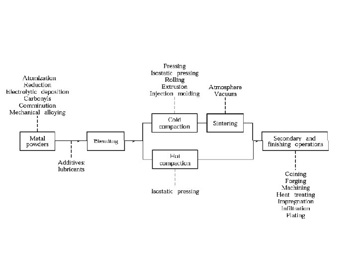
STEPS INVOLVED IN PM TECHNIQUE 1. Preparation of powders: very fine powders are obtained using various techniques. 2. Blending of powders: The fine powders are mixed along with a lubricant. The lubricant helps in imparting good flowability to the powders. 3. Compacting: The blended powder is compacted in a mold or die. 4. Sintering: The compacted mass is sintered at a high temperature in a furnace in a controlled atmosphere.
Continued. . . 5. Sizing: The sintered component is passed in a mold or dies to trim the component and achieve high dimensional accuracy. 6. Machining: If required final machining is done on some specific locations including drilling very small holes. 7. Treatment: Parts are subjected to deburring to remove any small projections 8. Inspection: Finally parts are inspected to check the quality.
ADVANTAGES OF POWDER METALLURGY Ø Virtually unlimited choice of alloys and non metallic with associated properties. Ø A variety of metal or non metal powders can be used. Ø Refractory materials are popularly processed by PM. Ø Can be very economical for mass production Ø Long term reliability through close control of dimensions and physical properties. Ø Very good material utilization - loss of material very less. Ø Minimization or elimination of Machining. Ø Very good surface finish can be easily obtained.
DISADVANTAGES • • Initial Investment cost high Limited part size and complexity High cost of powder material. High cost of tooling. Less stronger than wrought ones. Fracture toughness may be low. Less well known process. Health hazard to the operator due to very fine powder being processed
STEP. 1. PRODUCTION OF METAL POWDERS • Size: -0. 1 to 1000µm • The shape, purity, size depend on type of process used • The methods normally used for the production of metal powder are ü Atomization. ü Rotating Electrode Method ü Electrolytic deposition ü Pulverization
Atomization. ü Here the liquid metal stream is produced through a small orifice and the stream is broken by a jet of inert gas/water/air. ü Finely divided particles are obtained. ü The size of the particle depends on the temperature of the metal, flow rate, nozzle size & jet characteristics. ü A continuous uniform production of metal powders can be obtained.
Continued. .
Rotating Electrode Method ü In this method a consumable electrode(Metal rod) is rotated rapidly in a helium gas filled chamber. ü The centrifugal force breaks up the molten tip of the electrode, producing particles. ü Opposite to the spindle tip a non rotating electrode establishes an arc which heats the metal electrode which is rotating. ü Tiny droplets of metal are formed.
Continued. . .
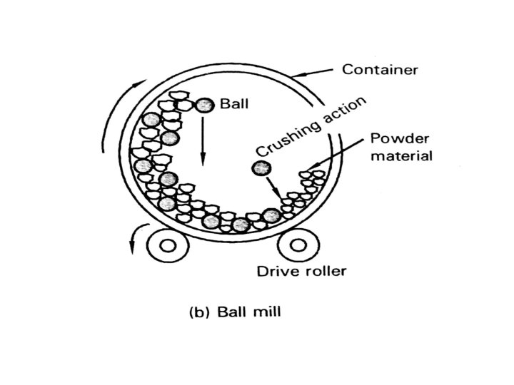
Pulverization ü In this method metals (brittle & less brittle) are crushed in a ball mill to produce small particles. ü In a ball mill, using rotating hollow cylinders, partly filled with steel or white cast iron balls, the metals are crushed. ü Repeated rotation of hollow cylinder results in crushing of the metal. Brittle metals will produce particles of angular shapes. Ductile metal will produce flake particles. (Hence, not suitable for powder metallurgy application).
ELECTROLYTIC DEPOSITION
STEP 2. BLENDING METAL POWDERS ü Here powders of two or more metals having different size & shapes are mixed to get a uniform mixture. ü The ideal mixture consists of Particles having uniform distribution. ü Powders of different metals are mixed to improve physical & mechanical properties as required. ü To improve the flow characteristics, lubricants are mixed with the metal powder.
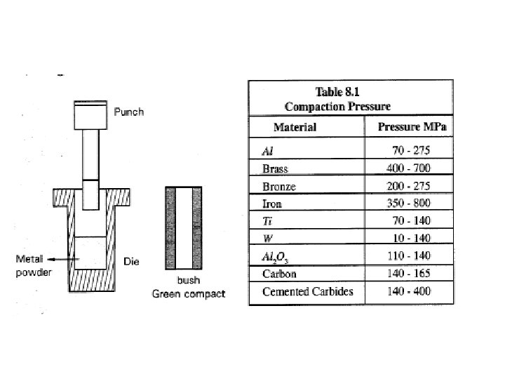
3. Compaction of Powder • In this step, the blended powders are pressed into shapes in dies using presses activated by hydraulic & mechanical means. • The pressure is around 70 -800 Mpa. • The pressed powder refer to as green strength • Pressing is generally done at room temp • The density of green compact depends upon pressure applied
• Methods of compaction Ø Using a punch and a die. Ø By Rolling. Ø By Extrusion. Ø By Injection moulding. Ø By Isostatic pressing
Using punch and a Die • Here a punch and a die assembly is used. • The metal powder mixture is filled in the die and the punch is forced on it. The powder gets compacted. • The range of pressure used for compaction is shown in the table.
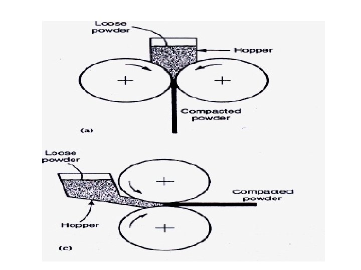
Powder Rolling • In powder rolling the powder is fed into the roll gap in a two high rolling mill and is compacted into a continuous strip at speeds up to 0. 5 m/s. • The process can be carried out at room temperature or at elevated temperatures.
Powder Extrusion
• Powders can be compacted by extrusion. • The metal powder is encased in a container and extruded. • A simple plunger cylinder arrangement is used • before sintering, preformed PM parts may be rolled or forged in a closed die to their shape.
Powder injection moulding
• Very fine metal powder are blended with a polymer or a wax based binder • The blended mixture undergoes compaction due to pressure obtain by screw container • The green compact are heated in an oven at low temp to burn off plastic
Cold isostatic pressing
Hot isostatic pressing
Sintering