Metal Casting By S K Mondal Sand casting

Metal Casting By S K Mondal

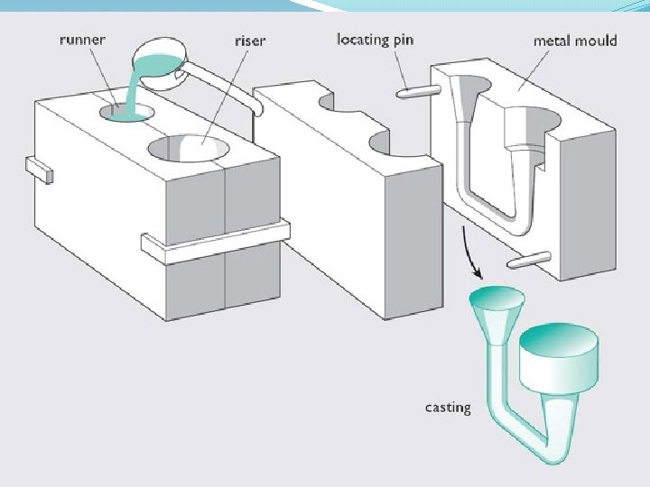
Sand casting � Sand casting uses ordinary sand as the primary mould material. � The sand grains are mixed with small amounts of other materials, such as clay and water, to improve mouldability and cohesive strength, and are then packed around a pattern that has the shape of the desired casting. � The pattern must be removed before pouring, the mold is usually made in two or more pieces. � An opening called a sprue hole is cut from the top of the mold through the sand connected to a system of channels called runners. Contd….

� The molten metal is poured into the sprue hole, flows through the runners, and enters the mold cavity through an opening called a gate. � Gravity flow is the most common means of introducing the metal into the mold. � After solidification, the mold is broken and the finished casting is removed. � The casting is then “fettled” by cutting off the ingate and the feeder head. � Because the mold is destroyed, a new mold must be made for each casting. Contd…

Sequential steps in making a sand casting �A pattern board is placed between the bottom (drag) and top (cope) halves of a flask, with the bottom side up. �Sand is then packed into the drag half of the mold. �A bottom board is positioned on top of the packed sand, and the mold is turned over, showing the top (cope) half of pattern with sprue and riser pins in place. �The cope half of the mold is then packed with sand. Contd…
, and the runner and")
�The mold is opened, the pattern board is drawn (removed), and the runner and gate are cut into the surface of the sand. �The mold is reassembled with the pattern board removed, and molten metal is poured through the sprue. �The contents are shaken from the flask and the metal segment is separated from the sand, ready for further processing.
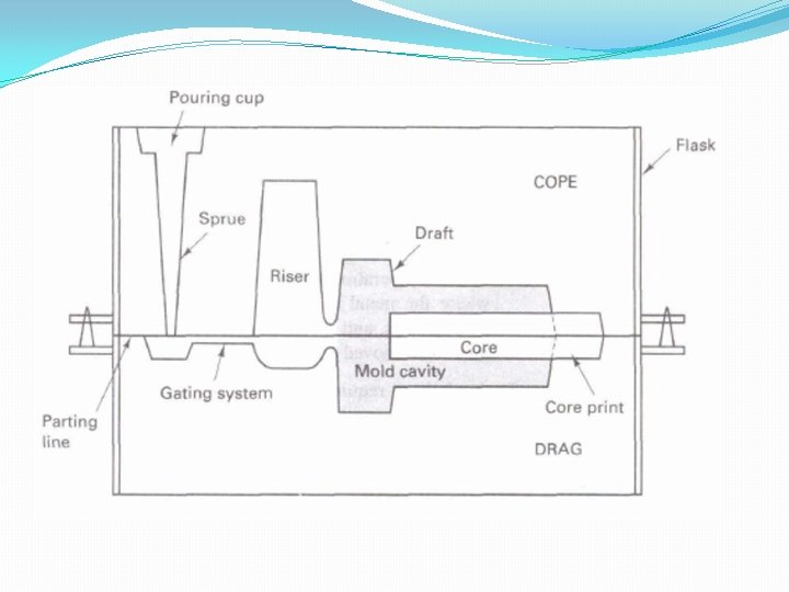


Casting Terms �Flask: A moulding flask is one which holds the sand mould intact. It is made up of wood for temporary applications or metal for long-term use. �Drag: Lower moulding flask. �Cope: Upper moulding flask. �Cheek: Intermediate moulding flask used in three- piece moulding. Contd…

�Pattern: Pattern is a replica of the final object to be made with some modifications. �Parting line: This is the dividing line between the two moulding flasks that makes up the sand mould. �Bottom board: This is a board normally made of wood, which is used at the start of the mould making. Contd…

�Moulding sand: The freshly prepared refractory material used for making the mould cavity. It is a mixture of silica, clay and moisture in appropriate proportions. �Backing sand: This is made up of used and burnt sand. �Core: Used for making hollow cavities in castings.

�Pouring basin: A small funnel-shaped cavity at the top of the mould into which the molten metal is poured. �Sprue: The passage through which the molten metal from the pouring basin reaches the mould cavity. �Runner: The passage ways in the parting plane through which molten metal flow is regulated before they reach the mould cavity. �Gate: The actual entry point through which molten Contd…

�Chaplet: Chaplets are used to support cores inside the mould cavity. �Chill: Chills are metallic objects, which are placed in the mould to increase the cooling rate of castings. �Riser: It is a reservoir of molten metal provided in the casting so that hot metal can flow back into the mould cavity when there is a reduction in volume of metal due to solidification Contd…

Padding �Tapering of thinner section towards thicker section is known as 'padding'. �This will require extra material. �If padding is not provided, centre line shrinkage or porosity will result in the thinner section.

IES-1996 Which of the following methods are used for obtaining directional solidification for riser design 1. Suitable placement of chills 2. Suitable placement of chaplets 3. Employing padding Select the correct answer. (a) 1 and 2 (b) 1 and 3 (c) 2 and 3 (d) 1, 2 and 3

Pattern A pattern is a replica of the object to be made by the casting process, with some modifications. The main modifications are � The addition of pattern allowances, �The provision of core prints, and �Elimination of fine details, which cannot be obtained by casting and hence are to be obtained by further processing

Pattern Allowances 1. Shrinkage or contraction allowance 2. Draft or taper allowance 3. Machining or finish allowance 4. Distortion or camber allowance 5. Rapping allowance

Shrinkage allowance �All metals shrink when cooling except perhaps bismuth. �This is because of the inter-atomic vibrations which are amplified by an increase in temperature. �The shrinkage allowance is always to be added to the linear dimensions. Even in case of internal dimensions. Contd…

Liquid shrinkage and solid shrinkage �Liquid shrinkage refers to the reduction in volume when the metal changes from liquid to solid state at the solidus temperature. To account for this, risers are provided in the moulds. �Solid shrinkage is the reduction in volume caused, when a metal loses temperature in the solid state. The shrinkage allowance is provided to take care of this reduction.

�Pattern Allowances Cast Iron Brass, Copper, Aluminium Steel Zinc, Lead 10 mm/m 15 mm/m 20 mm/m 25 mm/m �In grey cast iron and spheroidal graphite iron, the amount of graphitization controls the actual shrinkage. When graphitization is more, the shrinkage would be less and vice versa.

GATE 2011 A cubic casting of 50 mm side undergoes volumetric solidification shrinkage and volumetric solid contraction of 4% and 6% respectively. No riser is used. Assume uniform cooling in all directions. The side of the cube after solidification and contraction is (a) 48. 32 mm (b) 49. 90 mm (c) 49. 94 mm (d) 49. 96 mm

Draft �To reduce the chances of the damage of the mould cavity at the time of pattern removal, the vertical faces of the pattern are always tapered from the parting line. This provision is called draft allowance. �Inner surfaces of the pattern require higher draft than outer surfaces. �Draft is always provided as an extra metal.

DRAFT ALLOWANCE

Shake Allowance �At the time of pattern removal, the pattern is rapped all around the vertical faces to enlarge the mould cavity slightly to facilitates its removal. �It is a negative allowance and is to be applied only to those dimensions, which are parallel to the parting plane.

Distortion Allowance �A metal when it has just solidified is very weak and therefore is likely to be distortion prone. �This is particularly so for weaker sections such as long flat portions, V, U sections or in a complicated casting which may have thin and long sections which are connected to thick sections. �The foundry practice should be to make extra material provision for reducing the distortion.

Pattern Materials �Wood patterns are relatively easy to make. Wood is not very dimensionally stable. Commonly used teak, white pine and mahogany wood. �Metal patterns are more expensive but are more dimensionally stable and more durable. Commonly used CI, Brass, aluminium and white metal. �Hard plastics, such as urethanes, and are often preferred with processes that use strong, organically bonded sands that tend to stick to other pattern materials. �In the full-mold process, expanded polystyrene (EPS) is used. �Investment casting uses wax patterns.

The pattern material should be �Easily worked, shaped and joined �Light in weight �Strong, hard and durable �Resistant to wear and abrasion �Resistant to corrosion, and to chemical reactions �Dimensionally stable and unaffected by variations in temperature and humidity. �Available at low cost.

IES-1994 Which of the following materials can be used for making patterns? 1. Aluminium 2. Wax 3. Mercury 4. Lead Select the correct answer using the codes given below: Codes: (a) 1, 3 and 4 (b) 2, 3 and 4 (c) 1, 2 and 4 (d) 1, 2 and 3

Types of Pattern Single Piece Pattern Theseareinexpensiveandthesimplesttypeof patterns. As the name indicates, they are made of a single piece. Gated Pattern Gating and runner system are integral with the pattern. This would eliminate the hand cutting of the runners and gates and help in improving the productivity of a moulding.

Types of Pattern Split Pattern or Two Piece Pattern This the most iswidely used type pattern of intricate for castings. When the contour of the casting makes its withdrawal from the mould difficult, or when the depth of the casting is too high, then the pattern is split into two parts so that one part is in the drag and the other in the cope.

Types of Pattern �Cope and Drag Pattern These are similar to split patterns. In addition to splitting the pattern, the cope and drag halves of the pattern along with the gating and riser systems are attached separately to the metal or wooden plates along with the alignment pins. They are called the cope and drag patterns.

Types of Pattern �Match Plate Pattern The cope and drag patterns along with the gating and the risering are mounted on a single matching metal or wooden plate on either side.

Types of Pattern �Loose Piece Pattern This type of pattern is also used when the contour of the part is such that withdrawing the pattern from the mould is not possible.

Types of Pattern �Follow Board Pattern This type of pattern is adopted for those castings where there are some portions, which are structurally weak and if not supported properly are likely to break under the force of ramming.

Types of Pattern �Sweep Pattern It is used to sweep the complete casting by means of a plane sweep. These are used for generating large shapes, which are axisymmetrical or prismatic in nature such as bellshaped or cylindrical.

Types of Pattern �Skeleton Pattern A skeleton of the pattern made of strips of wood is used for building the final pattern by packing sand around the skeleton. After packing the sand, the desired form is obtained with the help of a strickle. This type of pattern is useful generally for very large castings, required in small quantities where large expense on complete wooden pattern is not justified.

Cooling Curve

Fluidity The ability of a metal to flow and fill a mold is known as fluidity. Pouring Temperature �The most important controlling factor of fluidity is the pouring temperature or the amount of superheat. �Higher the pouring temperature, the higher the fluidity. �Excessive temperatures should be avoided, however. At high pouring temperatures, metal-mold reactions are accelerated and the fluidity may be so great as to permit penetration. �Penetration is a defect where the metal not only fills the mold cavity but also fills the small voids between the sand particles in a sand mold.


Core �Used for making cavities and hollow projections. �All sides of core are surrounded by the molten metal and are therefore subjected to much more severe thermal and mechanical conditions and as a result the core sand should be of higher strength than the moulding sand.

Desired characteristics of a core � Green Strength: A core made of green sand should be strong enough to retain the shape till it goes for baking. � Dry Strength: It should have adequate dry strength so that when the core is placed in the mould, it should be able to resist the metal pressure acting on it. � Refractoriness: Since in most cases, the core is surrounded all around it is desirable that the core material should have higher refractoriness. Contd…

� Permeability: Gases evolving from the molten metal and generated from the mould may have to go through the core to escape out of the mould. Hence cores are required to have higher permeability. �Permeability Number: The rate of flow of air passing through a standard specimen under a standard pressure is termed as permeability number. �The standard permeability test is to measure time taken by a 2000 cu cm of air at a pressure typically of 980 Pa (10 g/cm 2), to pass through a standard sand specimen confined in a specimen tube. The standard specimen size is 50. 8 mm in diameter and a length of 50. 8 mm.

�Then, the permeability number, R is obtained by Where V= volume of air = 2000 cm 3 H = height of the sand specimen = 5. 08 cm p = air pressure, g/cm 2 A = cross sectional area of sand specimen = 20. 268 cm 2 T = time in minutes for the complete air to pass through Inserting the above standard values into the expression, we get

�Calculate the permeability number of sand if it takes 1 min 25 s to pass 2000 cm 3 of air at a pressure of 5 g/cm 2 through the standard sample.

IES 2007 What is permeability? Permeability is more important in the basic process of sand casting than porosity. Give one important reason for this feature. [2 marks]

�Collapsibility: At the time of cooling, casting shrinks, and unless the core has good collapsibility (ability to decrease in size) it is likely to provide resistance against shrinkage and thus can cause hot tears.

� Friability: The ability to crumble should be a very important consideration at the time of removal. � Smoothness: Surface of the core should be smooth for good finish to the casting. � Low Gas Emission

Core Sands �Used clay free silica sand. �Binders used are linseed oil, core oil, resins, dextrin, molasses, etc. �Core oils are mixtures of linseed, soy, fish and petroleum oils and coal tar. �The general composition of a core sand mixture could be core oil (1%) and water (2. 5 to 6%).
 is")
Carbon Dioxide Moulding �Sodium silicate (water glass, Si. O 2: Na 2 O) is used as a binder. This is essentially a quick process of core or mould preparation. �The mould is prepared with a mixture of sodium silicate and sand then treated with carbon dioxide for two to three minutes such that a dry compressive strength of over 1. 4 MPa is arrived. �The carbon dioxide is expected to form a weak acid, which hydrolyses the sodium silicate resulting in amorphous silica, which forms the bond. �The introduction of CO 2 gas starts the reaction by forming hydrated sodium carbonate (Na 2 CO 3 + H 2 O). Contd…

�The compressive strength of the bond increases with standing time due to dehydration. �Because of the high strength of the bond, the core need not be provided with any other reinforcements. �It does not involve any distortions due to baking and also better dimensional accuracies are achieved. �The sand mixture does not have good shelf life and therefore should be used immediately after preparation.
, zircon, or olivine sands.")
Moulding Sand Composition �Sand: Ordinary silica Sand (Si. O 2), zircon, or olivine sands. �Clay: Acts as binding agents mixed to the moulding sands Kaolinite or fire clay (Al 2 O 3 2 Si. O 2 2 H 2 O), and Bentonite (Al 2 O 3 4 Si. O 2 H 2 O n. H 2 O). �Water: Clay is activated by water.

Other Additives �Cereal binder up to 2% increases the strength. �Pitch if used up to 3% would improve the hot strength. �Saw dust up to 2% may improve the collapsibility by slowly burning, and increase the permeability. �Other materials: sea coal, asphalt, fuel oil, graphite, molasses, iron oxide, etc.

Moulding Sand Properties �Porosity or Permeability: Permeability or porosity of the moulding sand is the measure of its ability to permit air to flow through it. �Strength: It is defined as the property of holding together of sand grains. A moulding sand should have ample strength so that the mould does not collapse or get partially destroyed during conveying, turning over or closing. �Refractoriness: It is the ability of the moulding sand mixture to withstand the heat of melt without showing any signs of softening or fusion. Contd…

�Plasticity: It is the measure of the moulding sand to flow around and over a pattern during ramming and to uniformly fill the flask. �Collapsibility: This is the ability of the moulding sand to decrease in volume to some extent under the compressive forces developed by the shrinkage of metal during freezing and subsequent cooling. �Adhesiveness: This is the property of sand mixture to adhere to another body (here, the moulding flasks). The moulding sand should cling to the sides of the moulding boxes so that it does not fall out when the flasks are lifted and turned over. This property depends on the type and amount of binder used in the sand mix.

Other Sands �Facing sand: The small amount of carbonaceous material sprinkled on the inner surface of the mold cavity to give a better surface finish to the castings. �Backing sand: It is what constitutes most of the refractory material found in the mould. This is made up of used and burnt sand. �Green Sand: The molding sand that contains moisture is termed as green sand. The green sand should have enough strength so that the constructed mould retains its shape. �Dry sand: When the moisture in the moulding sand is completely expelled, it is called dry sand.
 grain size number, defined")
Grain size number �ASTM (American Society for Testing and Materials) grain size number, defined as N �Where N is the number of grains per square inch visible in a prepared specimen at 100 X and n is the ASTM grain-size number. �Low ASTM numbers mean a few massive grains; high numbers refer to many small grains.

Casting Yield The casting yield is the proportion of the actual casting mass, w, to the mass of metal poured into the mould, W, expressed as a percentage.

Gating System Contd…

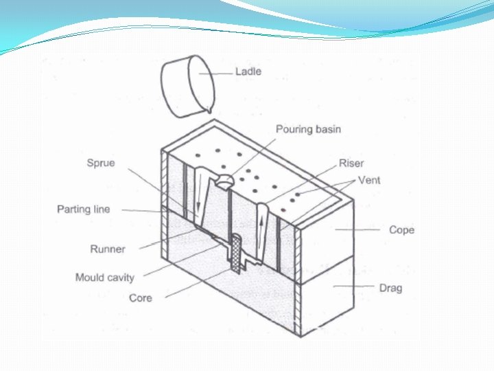
Gating System �Pouring basin: A small funnel shaped cavity at the top of the mould into which the molten metal is poured. �Sprue: The passage through which the molten metal, from the pouring basin, reaches the mould cavity. In many cases it controls the flow of metal into the mould. �Runner: The channel through which the molten metal is carried from the sprue to the gate. Contd…

�Ingate: A channel through which the molten metal enters the mould cavity. �Vent: Small opening in the mould to facilitate escape of air and gases.

Types of Gate or In-gate Top gate: Causes turbulence in the mould cavity, it is prone to form dross, favourable temperature gradient towards the gate, only for ferrous alloys. Bottom gate: No mould erosion, used for very deep moulds, higher pouring time, Causes unfavourable temperature gradients. Parting Gate: most widely used gate, easiest and most economical in preparation. Step Gate: Used for heavy and large castings, size of ingates are normally increased from top to bottom.

IES 2011 In light metal casting, runner should be so designed that: 1. It avoids aspiration 2. It avoids turbulence 3. The path of runner is reduced in area so that unequal volume of flow through each gate takes place (a) 1 and 2 only (b) 1 and 3 only (c) 2 and 3 only (d) 1, 2 and 3

The goals for the gating system �To minimize turbulence to avoid trapping gasses into the mold �To get enough metal into the mold cavity before the metal starts to solidify �To avoid shrinkage �Establish the best possible temperature gradient in the solidifying casting so that the shrinkage if occurs must be in the gating system not in the required cast part. �Incorporates a system for trapping the non-metallic inclusions.

Types of Gating Systems The gating systems are of two types: �Pressurized gating system �Un-pressurized gating system

Pressurized Gating System �The total cross sectional area decreases towards the mold cavity �Back pressure is maintained by the restrictions in the metal flow �Flow of liquid (volume) is almost equal from all gates �Back pressure helps in reducing the aspiration as the sprue always runs full �Because of the restrictions the metal flows at high velocity leading to more turbulence and chances of mold erosion.

Un-Pressurized Gating System �The total cross sectional area increases towards the mold cavity �Restriction only at the bottom of sprue �Flow of liquid (volume) is different from all gates �Aspiration in the gating system as the system never runs full �Less turbulence.

Sprue Design �Sprue: Sprue is the channel through which the molten metal is brought into the parting plane where it enters the runners and gates to ultimately reach the mould cavity. �The molten metal when moving from the top of the cope to the parting plane gains in velocity and some lowpressure area would be created around the metal in the sprue. �Since the sand mould is permeable, atmospheric air would be breathed into this low-pressure area which would then be carried to the mould cavity. �To eliminate this problem of air aspiration, the sprue is tapered to gradually reduce the cross section as it moves away from the top of the cope as shown in Figure below. Contd… (b).

The exact tapering can be obtained by the equation of continuity. Denoting the top and choke sections of The sprue by the subscripts’t’ and 'c' respectively, we get Contd…

Since the velocities are proportional to the square of the potential heads, as can be derived from Bernoulli's equation, Where H = actual sprue height and ht = h + H

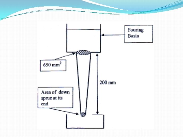
GATE-2007 A 200 mm long down sprue has an area of cross section of 650 mm 2 where the pouring basin meets the down sprue (i. e. at the beginning of the down sprue). A constant head of molten metal is maintained by the pouring basin. The Molten metal flow rate is 6. 5 × 105 mm 3/s. Considering the end of down sprue to be open to atmosphere and an acceleration due to gravity of 104 mm/s 2, the area of the down sprue in mm 2 at its end (avoiding aspiration effect) should be (a)650. 0 (b)350. 0 (c)290. 7 (d)190. 0 Contd…

Gating ratio �Gating ratio is defined as: Sprue area: Runner area: Ingate area. �For high quality steel castings, a gating ratio of 1: 2: 2 or 1: 2: 1. 5 will produce castings nearly free from erosion, will minimize oxidation, and will produce uniform flow. �A gating ratio of 1: 4: 4 might favour the formation of oxidation defects.

Risers and Riser Design �Risers are added reservoirs designed to feed liquid metal to the solidifying casting as a means of compensating for solidification shrinkage. �To perform this function, the risers must solidify after the casting. �According to Chvorinov's rule, a good shape for a riser would be one that has a long freezing time (i. e. , a small surface area per unit volume). �Live risers (also known as hot risers) receive the last hot metal that enters the mold and generally do so at a time when the metal in the mold cavity has already begun to cool and solidify.
 = B (V/A) n where n = 1.")
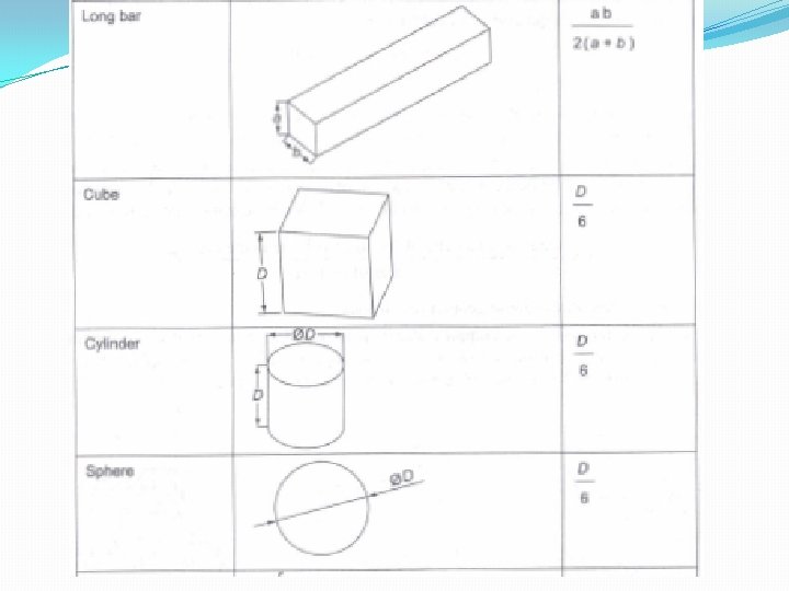
Chvorinov’s rule �Total solidification time (ts) = B (V/A) n where n = 1. 5 to 2. 0 [Where, B = mould constant and is a function of (mould material, casting material, and condition of casting] n = 2 and triser = 1. 25 tcasting or For cylinder of diameter D and height H

IES 2011 The relationship between total freezing time t, volume of the casting V and its surface area A, according to Chvorinov’s rule is : Where K is a constant

IES-1998 A spherical drop of molten metal of radius 2 mm was found to solidify in 10 seconds. A similar drop of radius 4 mm would solidify in (a) 14. 14 seconds (b) 20 seconds (c) 28. 30 seconds (d) 40 seconds

GATE-2013 A cube shaped casting solidifies in 5 min. The solidification time in min for a cube of the same material, which is 8 times heavier than the original casting, will be (a) 10 (b) 20 (c) 24 (d) 40

GATE-2003 With a solidification factor of 0. 97 x 106 s/m 2, the solidification time (in seconds) for a spherical casting of 200 mm diameter is (a) 539 (b) 1078 (c) 4311 (d) 3233

IES-2006 According to Chvorinov's equation, the solidification time of a casting is proportional to: (a) v 2 (b) v (c) 1/v (d) 1/v 2 Where, v = volume of casting
 Solidification time of a metallic alloy casting is (a) Directly")
GATE – 2010 (PI) Solidification time of a metallic alloy casting is (a) Directly proportional to its surface area (b) Directly proportional to the specific heat of the cast material (c) Directly proportional to thermal diffusivity of the molten metal (d)Inversely temperature. proportional to the pouring

GATE-2007 Volume of a cube of side 'l' and volume of a sphere of radius ‘r’ are equal. Both the cube and the sphere are solid and of same material. They are being cast. The ratio of the solidification time of the cube to the same of the sphere is:
 In a sand casting process, a sphere and a cylinder of")
GATE -2011 (PI) In a sand casting process, a sphere and a cylinder of equal volumes are separately cast from the same molten metal under identical conditions. The height and diameter of the cylinder are equal. The ratio of the solidification time of the sphere to that of the cylinder is (a) 1. 14 (b) 0. 87 (c) 1. 31 (d) 0. 76
 A solid cylinder of diameter D and height equal to D, and")
GATE-2009 (PI) A solid cylinder of diameter D and height equal to D, and a solid cube of side L are being sand cast by using the same material. Assuming there is no superheat in both the cases, the ratio of solidification time of the cylinder to the solidification time of the cube is (a) (L/D)2 (b) (2 L/D)2 (c) (2 D/L)2 (d) (D/L)2

IES - 2012 The ratio of surface area of volume for a unit volume of riser is minimum in case of (a) Cylindrical riser (b) Spherical riser (c) Hemispherical riser (d) Cuboids riser

IES 2011 Conventional �A round casting is 20 mm in diameter and 50 mm in length. Another casting of the same metal is elliptical in cross section, with a major to minor axis ratio of 2, and has the same length and cross-sectional area as the round casting. Both pieces are cast under the same conditions. What is the difference in the solidification times of the two castings ? [10 – Marks]

Conventional Question ESE 2003 Compare the solidification time of two optimum side – risers of the same volume with one has cylindrical shape and other is parallopiped. Marks] [30

Modulus Method �It has been empirically established that if the modulus of the riser exceeds the modulus of the casting by a factor of 1. 2, the feeding during solidification would be satisfactory. MR = 1. 2 Mc �Modulus = volume/Surface area �In steel castings, it is generally preferable to choose a riser with a height-to-diameter ratio of 1. Contd…
")
Conventional Question IES-2008 �Calculate the size of a cylindrical riser (height and diameter equal) necessary to feed a steel slab casting of dimensions 30 x 6 cm with a side riser, casting poured horizontally into the mould. [Use Modulus Method] [10 - Marks]

Caine’s Method Freezing ratio = ratio of cooling characteristics of casting to the riser. The riser should solidify last so x > 1 According to Caine Y= X= and a, b, c are constant.

Table: Constants in Caine’s Method
")
Conventional Question IES-2007 �Calculate the size of a cylindrical riser (height and diameter equal) necessary to feed a steel slab casting of dimensions 25 x 5 cm with a side riser, casting poured horizontally into the mould. [Use Caine’s Method] [ For steel a = 0. 10, b = 0. 03 and c = 1. 00 ]

Chills �External chills are masses of high-heat-capacity, high-thermalconductivity material that are placed in the mould (adjacent to the casting) to accelerate the cooling of various regions. Chills can effectively promote directional solidification or increase the effective feeding distance of a riser. They can often be used to reduce the number of risers required for a casting. �Internal chills are pieces of metal that are placed within the mould cavity to absorb heat and promote more rapid solidification. Since some of this metal will melt during the operation, it will absorb not only the heat-capacity energy, but also some heat of fusion. Since they ultimately become part of the final casting, internal chills must be made from the same alloy as that being cast.

Cupola �Cupola has been the most widely used furnace for melting cast iron. �In hot blast cupola, the flue gases are used to preheat the air blast to the cupola so that the temperature in the furnace is considerably higher than that in a conventional cupola. Coke is fuel and Lime stone (Ca. CO 3) is mostly used flux. �Cost of melting low. �Main disadvantages of cupola is that it is not possible to produce iron below 2. 8% carbon. �Steel can be also prepared in cupola by employing duplexing and triplexing operations.
: Cupola furnace is not employed for melting steel in")
IES - 2012 Statement (I): Cupola furnace is not employed for melting steel in foundry Statement (II): The temperatures generated within a cupola are not adequate for melting Steel (a) Both Statement (I) and Statement (II) are individually true and Statement (II) is the correct explanation of Statement (I) (b) Both Statement (I) and Statement (II) are individually true but Statement (II) is not the correct explanation of Statement (I) (c) Statement (I) is true but Statement (II) is false (d) Statement (I) is false but Statement (II) is true

Electric Arc Furnace �For heavy steel castings, the open-hearth type of furnaces with electric arc or oil fired would be generally suitable in view of the large heat required for melting. �Electric arc furnaces are more suitable for ferrous materials and are larger in capacity.

Crucible Furnace �Smaller foundries generally prefer the crucible furnace. �The crucible is generally heated by electric resistance or gas flame. Induction Furnace �The induction furnaces are used for all types of materials, the chief advantage being that the heat source is isolated from the charge and the slag and flux get the necessary heat directly from the charge instead of the heat source.

Ladles �Two types of ladles used in the pouring of castings.
 Impurities in the molten metal are prevented from reaching the mould")
Casting Cleaning (fettling) Impurities in the molten metal are prevented from reaching the mould cavity by providing a (i) Strainer (ii) Bottom well (iii) Skim bob

Pouring time Time taken to fill the mould with top gate Where A = Area of mould H = Height of mould A g = Area of Gate H m = Gate height Time taken to fill the mould with bottom gate
 A mould having dimensions 100 mm × 90 mm × 20 mm")
GATE-2012 (PI) A mould having dimensions 100 mm × 90 mm × 20 mm is filled with molten metal through a gate as shown in the figure. For height h and cross-sectional area A, the mould filling time is t 1. The height is now quadrupled and the cross-sectional area is halved. The corresponding filling time is t 2. The ratio t 2/t 1 is

Expression for choke area Where m = mass of the casting, kg = Density of metal, kg / m 3 t = pouring time c = Efficiency factor and is the function of gate system used H = Effective head of liquid metal = h for top gate Contd…

H=h=h- top gate for bottom gate for parting line gate bottom gate

IES 2009 � 2 marks

Casting Defects The following are the major defects, which are likely to occur in sand castings: �Gas defects �Shrinkage cavities �Molding material defects �Pouring metal defects �Mold shift.

Gas Defects �A condition existing in a casting caused by the trapping of gas in the molten metal or by mold gases evolved during the pouring of the casting. �The defects in this category can be classified into blowholes and pinhole porosity. �Blowholes are spherical or elongated cavities present in the casting on the surface or inside the casting. �Pinhole porosity occurs due to the dissolution of hydrogen gas, which gets entrapped during heating of molten metal.

Shrinkage Cavities �These are caused by liquid shrinkage occurring during the solidification of the casting. �To compensate for this, proper feeding of liquid metal is required. For this reason risers are placed at the appropriate places in the mold. �Sprues may be too thin, too long or not attached in the proper location, causing shrinkage cavities. �It is recommended to use thick sprues to avoid shrinkage cavities.

Molding Material Defects �Cuts and washes, �Scab �Metal penetration, �Fusion, and �Swell

Cut and washes �These appear as rough spots and areas of excess metal, and are caused by erosion of molding sand by the flowing metal. �This is caused by the molding sand not having enough strength and the molten metal flowing at high velocity. �The former can be taken care of by the proper choice of molding sand the latter can be overcome by the proper design of the gating system.

Scab �This defect occurs when a portion of the face of a mould lifts or breaks down and the recess thus made is filled by metal. �When the metal is poured into the cavity, gas may be disengaged with such violence as to break up the sand, which is then washed away and the resulting cavity filled with metal. �The reasons can be: - too fine sand, low permeability of sand, high moisture content of sand uneven mould ramming.

Metal penetration �When molten metal enters into the gaps between sand grains, the result is a rough casting surface. �This occurs because the sand is coarse or no mold wash was applied on the surface of the mold. The coarser the sand grains more the metal penetration.

Fusion �This is caused by the fusion of the sand grains with the molten metal, giving a brittle, glassy appearance on the casting surface. �The main reason for this is that the clay or the sand particles are of lower refractoriness or that the pouring temperature is too high.

Swell Under the influence of metallostatic forces, the mold wall may move back causing a swell in the dimension of the casting. A proper ramming of the mold will correct this defect. Inclusions Particles of slag, refractory materials sand or deoxidation products are trapped in the casting during pouring solidification. The provision of choke in the gating system and the pouring basin at the top of the mold can prevent this defect

Pouring Metal Defects The likely defects in this category are �Mis-runs and �Cold shuts � A mis-run is caused when the metal is unable to fill the mold cavity completely and thus leaves unfilled cavities. �A cold shut is caused when two streams while meeting in the mold cavity, do not fuse together properly thus forming a discontinuity in the casting. Contd…

�The mis-run and cold shut defects are caused either by a lower fluidity of the mold or when the section thickness of the casting is very small. Fluidity can be improved by changing the composition of the metal and by increasing the pouring temperature of the metal.

Mold Shift The mold shift defect occurs when cope and drag or molding boxes have not been properly aligned.

Cast Aluminium Code �Four digit identification system �First digit indicates alloy group 1 – Aluminium, 99% or more 2 – copper 3 – Silicon, with copper and/or magnesium 4 – silicon 5 – magnesium 6 – not used 7 – zinc 8 – tin 9 – other elements

Cast Aluminium Code Contd. . �Second two digits identify the aluminium alloy or indicate the aluminium purity. �The last digit is separating from the other three by a decimal point and indicates the product form; that is, castings or ingots �A modification of the original alloy is indicated by a serial letter before the numerical designation. �Alloy A 514. 0 indicates an aluminium alloy casting with magnesium as the principal alloy. One modification to the original alloy has made, as indicated by the letter A.
")
IES 2011 In the designation of Aluminium casting A 514. 0 indicates : (a) Aluminium purity (b) Aluminium content (c) Percentage of alloy element (d) Magnesium Content Ans. (d)

- Slides: 123