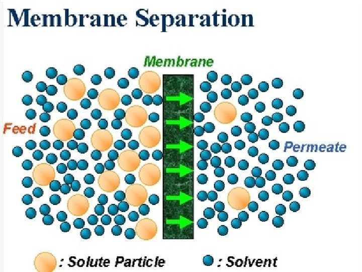
Membrane Processes A membrane is a selective barrier

Membrane Processes • A membrane is a selective barrier that permits the separation of certain species in a fluid by combination of sieving and diffusion mechanisms • Membranes can separate particles and molecules and over a wide particle size range and molecular weights
 • Pressure (ΔP) – Reverse osmosis (RO) – Nanofiltration (NF)")
Membrane Processes (driving forces) • Pressure (ΔP) – Reverse osmosis (RO) – Nanofiltration (NF) – Ultrafiltration (UF) – Microfiltration (MF) • Concentration (ΔC) – Pervaporation – Dialysis • Electrical potential (ΔΨ) – Electrodialysis reversal

Membrane Processes Four common types of membranes: Reverse Osmosis Nanofiltration Ultrafiltration Microfiltration
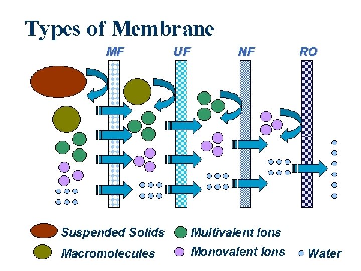
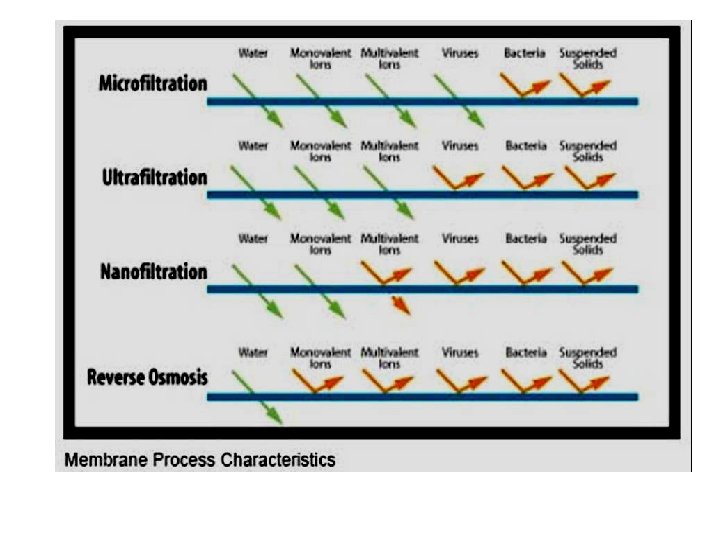

Dissolved salts Suspended solids Colloids Viruses Bacteria Parasites Org. macro. molecules 0. 0001 0. 1 polio virus Reverse Osmosis Nanofiltration smallest microorganis m 1 Cryptosporidium Ultrafiltration 100 mm 10 hair Sand filtration Microfiltration

MICROFILTRATION

MICROFILTRATION • • • largest pores a sterile filtration with pores 0. 1 -10. 0 microns micro-organisms cannot pass through them operated at low pressure differences used to filter particles. may or may not be assymmetric

MICROFILTRATION • wide array of applications: – parenterals and sterile water for pharmaceutical industry – food & beverages – chemical industry – microelectronics industry – fermentation – laboratory/analytical uses

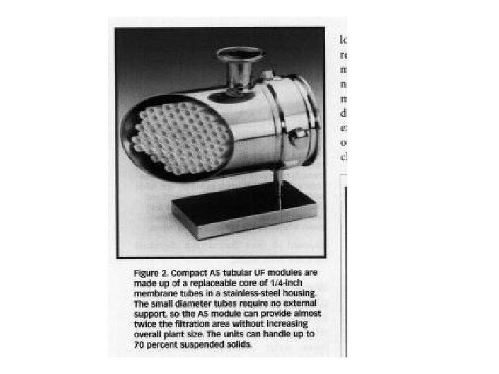
ULTRAFILTRATION

ULTRAFILTRATION • to separate a solution; mixture of desirable and undesirable components • has smaller pores than microfiltration membranes • driving force → pressure differential (2 -10 bars to 25 -30 bars) • used to separate species with pore sizes (103 -0. 1 microns) • Can be obtained down to a a molecular weight cutoff (MWCO) level of 1000 Daltons (Da) and up yo as high as 1 000 Da. • assymmetric; the pores are small

ULTRAFILTRATION • wide range of applications : – oil emulsion waste treatment – treatment of whey in dairy industries – concentration of biological macromolecules – electrocoat paint recovery – concentration of textile sizing – concentration of heat sensitive proteins for food additives – many more …

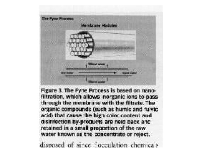
NANOFILTRATION

NANOFILTRATION • less pore sizes than ultrafiltration membranes • the mass transfer mechanism is diffusion & separate small molecules from the solution • cellulosic acetate and aromatic polyamide type membranes (salt rejections; 95% for divalent salts to 40% for monovalent salts) • can typically operate at higher recoveries; conserving total water usage due to a lower concentrate stream flow rate (advantage over reverse osmosis) • not effective on small molecular weight organics (e. g. methanol)

NANOFILTRATION • typical applications: – desalination of food, dairy and beverage products or byproducts – partial desalination of whey, UF permeate or retentate as required – desalination of dyes and optical brighteners – purification of spent clean-in-place (CIP) chemicals – color reduction or manipulation of food products – concentration of food, dairy and beverage products or byproducts – fermentation byproduct concentration

REVERSE OSMOSIS

REVERSE OSMOSIS • the process eliminates the dissolved solids, bacteria, viruses and other germs contained in the water • only water molecules allowed to pass via very big pressure • assymmetric type membranes (decrease the driving pressure of the flux) • almost all membranes are made polymers, cellulosic acetate and matic polyamide types rated at 96%-99+% Na. Cl rejection

REVERSE OSMOSIS • extensive applications: – potable water from sea or brackish water – ultrapure water food processing and electronic industries – harmaceutical grade water – water for chemical, pulp & paper industry – waste treatment

Advantages of Membrane Processes • • They are usually continuous Comparatively low energy utilisation No phase change of contaminants Small temperature change Modular design Minimum of moving parts Physical separation of contaminants

Comparison of Membrane Processes Ultrafiltration Reverse Osmosis Microfiltration Operates on difficult colloidal water Requires extensive pretreatment of colloids Rapidly fouled by colloids giving high replacement costs Low pressure (2 -6 bar) High pressure (10 -30 bar) Low pressure (2 -4 bar) Low energy consumption High energy Low energy High recovery (up to 95%) Low recovery (50 -80%) 100% recovery Chemical tolerance p. H 1 -13 p. H 2 -11 p. H 1 -13 High temperature up to 80 o. C 45 o. C max. High temperatures possible High resistance to oxidising agents Limited resistance to oxidising agents High resistance to oxidising agents Stream sterilisable Stream sterilisation not Stream sterilisation possible membranes available possible Hygienic module designs Modules not as hygienic available Hygienic designs available

Membrane Configurations

1. Flat membranes • Mainly used to fabricate and used • In some cases modules are stacked together like a multilayer sandwich or plate-and-frame filter press • Three basic structures are commonly uses for membranes: homogeneous (no significant variation in pore diameter from the filtering surface to the other side), asymmetric (has a thin layer next to the filtering surface that has very pores), and composite (containing very small pores next to the filtering surface; however, the thin and thick layers of this membrane are made of two different types of material)

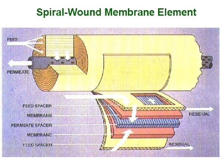
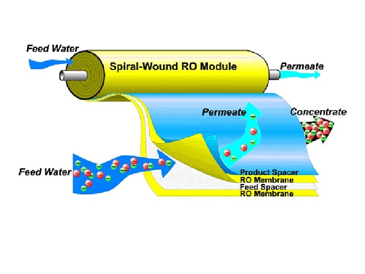
Membrane Configurations 2. Spiral wound membranes • Constructed from flat sheet membranes separated by spacer screens • Consists of a sandwich of four sheets wrapped around a central core of a perforated collecting tube • The four sheets consist of a top sheet of an open separator grid for feed channel, a membrane, a porous felt backing for the permeate channel, and another membrane • The feed solution is fed into one end of the module and flows through the separator screens along the surface of the membranes • The retentate is the collected in the other end of the module • The permeate spirals radially inward, eventually to be collected through a central tube • The flow in these systems tend to be turbulent • The main disadvantage of spiral-wound modules is that they are susceptible to fouling by particulates because of the narrow and irregular flow through spacers

Membrane Configurations Spiral-wound elements and assembly Local solution flow paths for spiral-wound separator.

Membrane Configurations 3. Hollow-fiber membranes • The membranes are in the shape of very-small-diameter hollow fibers • Typically, the high-pressure feed enters the shell side at one end and leaves at the other end • The hollow fibers are closed at one end of the tube bundles • The permeate solution inside the fibers flows countercurrent to the shell-side flow and is collected in a chamber where the open ends of the fibers terminate • Then the permeate exits the device

Spiral wound
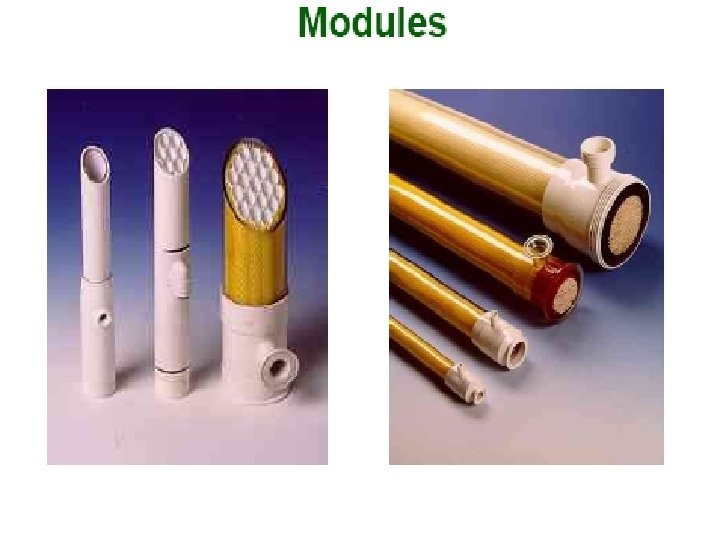

Ceramic Membrane Elements

Spiral UF system

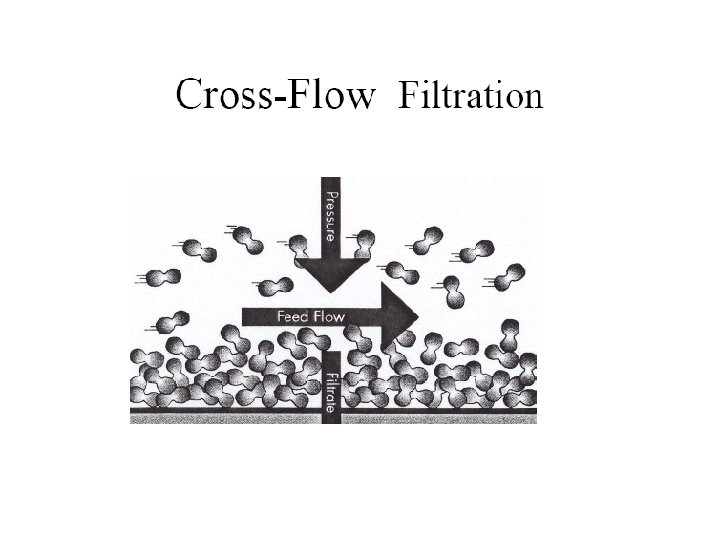
Pressure requirements are based on osmotic pressure for R. O. , osmotic pressure and fluid mechanical frictional headloss (straining) for nanofiltration, and purely fluid mechanical frictional headloss (straining) for ultra- and microfiltration.

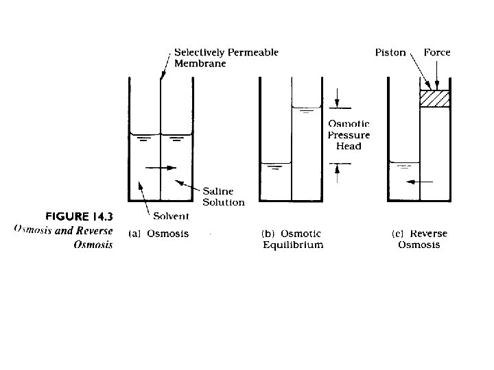
If clean water and water with some concentration of solute are separated by a semi-permeable membrane (permeable to only water) water will be transported across the membrane until increases hydrostatic pressure on the solute side will force the process to stop.

Water flux through the membrane is the most important design and operational parameter. Next most important is solute exclusion. Some solute will diffuse (by molecular diffusion) through the membrane because there will be a significant gradient of the solute across the membrane. Water Flux:

Fouling of membranes due to accumulation of solute/particulates at the membrane interface has to be addressed for economic reasons. The membranes are too expensive to be replaced for reasons of fouling.

Fouling issue Traditional membrane technology is generally affected by fouling. This long-term loss in throughput capacity is due primarily to the formation of a boundary layer that builds up naturally on the membrane surface during the filtration process. In addition to cutting down on the flux performance of the membrane, this boundary or gel layer acts as a secondary membrane reducing the native design selectivity of the membrane in use. This inability to handle the buildup of solids has also limited the use of membranes to low-solids feed streams.

Fouling

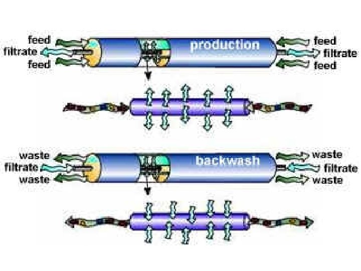
There are various ways to reduce this fouling such as: • Periodic pulsing of feed • Periodic pulsing filtrate (backwashing) • Increasing shear at by rotating membrane • Vibrating membrane (VSEP technology)

Vibrating shear to prevent fouling VSEP Technology

A common method to clean the membrane system is to just reverse the flow pattern:

Membrane Processes are becoming popular because they are considered “Green” technology - no chemicals are used in the process.

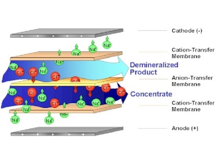
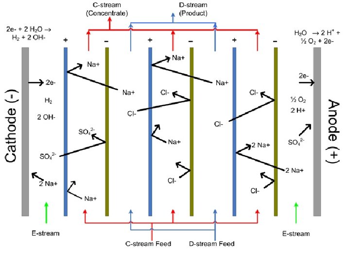
Electrodialysis: In the ED process a semi-permeable barrier allows passage of either positively charged ions (cations) or negatively charged ions (anions) while excluding passage of ions of the opposite charge. These semi-permeable barriers are commonly known as ion-exchange, ion-selective or electrodialysis membranes.

Current required in amps:

Voltage required is determined by: E=Ix. R R = resistance across unit (all cells + feed and product water), ohms. Generally in range of 10 – 50 ohms. I, in amps, as determined in previous calculation.

Electrode reactions: Small amounts of hydrogen gas are generated at the cathode: At the anode small amounts of oxygen gas are generated:
- Slides: 55